X RAY TUBES BY DR MONICA PATIL INTRODUCTION

X –RAY TUBES BY DR. MONICA PATIL
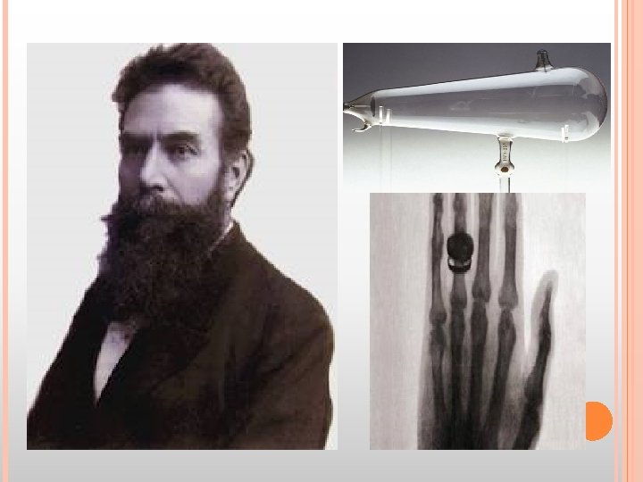

INTRODUCTION X-Rays are electromagnetic radiation produced when a fast moving stream of electrons is suddenly decelerated at the target anode.
")
STRUCTURE OF AN ATOM Atom has a central nucleus which has nucleons: Protons(+very charged) Neutrons(no charge)

THIS IS SURROUNDED DIFFERENT SHELLS. These shells are labelled as K , L & M from inside out. Ø These shells hav sub shells within them Ø (2 n-1) K : no subshell L: 3 subshells-lowest -middle -highest Ø BY ELECTRONS IN

Nucleus : positive charge Electrons : negative charge Ø Thus there exists a force of attraction between the two which keeps them together termed as BINDING FORCE OF AN ELECTRON. ØIt is inversely proportional to square of distance between nucleus. electron and

Binding energy is defined as the energy given to raise the energy of an electron to zero. For tungsten (most common anode material used) : K shell binding energy is 70 kev L shell binding energy is 11 kev L shell electron has 59 kev more energy than K electron.

TRANSITION Ø OF ELECTRONS: To a lower energy shell : Ex: L to K shell - loss of energy occurs To a higher energy shell : Ex: K to L shell - absorption of energy occurs Ø This loss or absorption of energy is equal to the difference in the binding energies of the two shells. Ø

Ø Lowest sub shell of L shell to K shell not possible known as FORBIDDEN TRANSITION. Ø Other L sub-shells to K shell : K-alpha Ø M shell to K shell : K- beta

PROCESS OF X-RAY GENERATION
 Characteristic radiation (reactions")
2 PROCESSE S General Radiation/ Bremsstrahlung (reaction of electrons with nucleus) Characteristic radiation (reactions of electrons with shell electrons)
")
GENERAL/BREMSSTAHLUNG RADIATION: From German : breaking radiation Original path of incident electrons (from cathode) Deflection in original path due to positively charge nucleus (of anode) Loss of kinetic energy Emission of x-ray photon.

Electrons gives up only a part of its energy in one time , thus they penetrate through multiple layers before giving up all of its energy. Rarely there will be head on collision with the nucleus: all energy lost as a single photon of energy. Thus, only few x-rays are produced, 99% lost as heat. Energy of the photon is inversely related to its wavelength , since different energy photons are emitted, wavelength varies in general radiation.

CHARACTERISTIC RADIATION: Ø Ejection of K electron Ø Creation of Vacancy Ø Jump of electron from L shell. Ø Release of x ray photon.

ØIn routine practice most of radiations are due to General Radiation except when Molybdenum target is used as in mammography characteristic radiation forms the main part.

ØQuantity - atomic no. - square of Kvp. - x-ray tube current. ØQuality/energy - tube potential(Kvp)

ØAt lower atomic no. general radiation becomes less efficient & characteristic radiation assumes greater importance. ØCombination of low atomic no. & low voltage is used in breast imaging by using molybdenum as the target material.

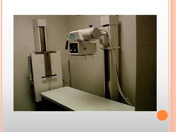
X-RAY MACHINE Ø It has the following part: - x-ray tube - operating console -high voltage section -film holder, grid cabinet/ table

OPERATING CONSOLE:

GENERATOR

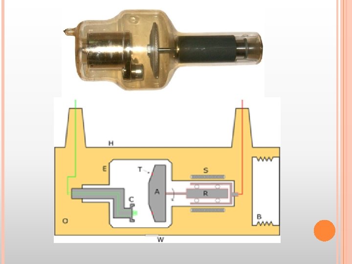
STRUCTURE OF AN X-RAY TUBE 3 basic components: - Glass enclosure - Cathode - Anode

GLASS ENCLOSURE: It is made of pyrex glass. Ø The 2 electrodes are placed in vaccum, this is necessary as: -collision of the electrons with the gas molecules would cause secondary electrons to be prod, causing wide variation in the energy of the x-rays produced. Ø

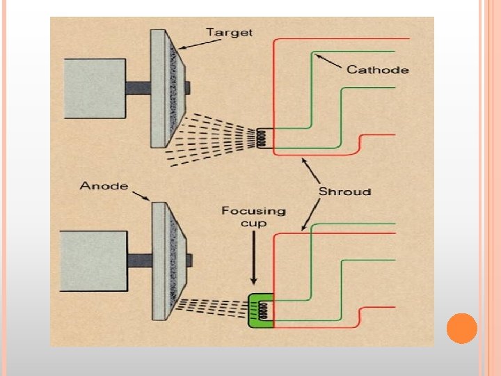
CATHODE: Source of electrons. Ø -ve terminal. Ø Cathode = filament. Ø Components : - Tungsten filament - Connecting wires - Focusing cup Ø Newer tubes have 2 filament mounted side by , one usually longer than the other , only 1 fil. Is used for a given exposure. Ø

TUNGSTEN FILAMENT: 0. 2 mm in diameter. Ø Coiled to form vertical spiral - 0. 2 cm in diameter - <1 cm in length. Ø Chosen as the filament material as: -high atomic no. -high melting point(3370 o. C) -little tendency to vaporize, hence long life. -strong & can be drawn into thin wires. Ø

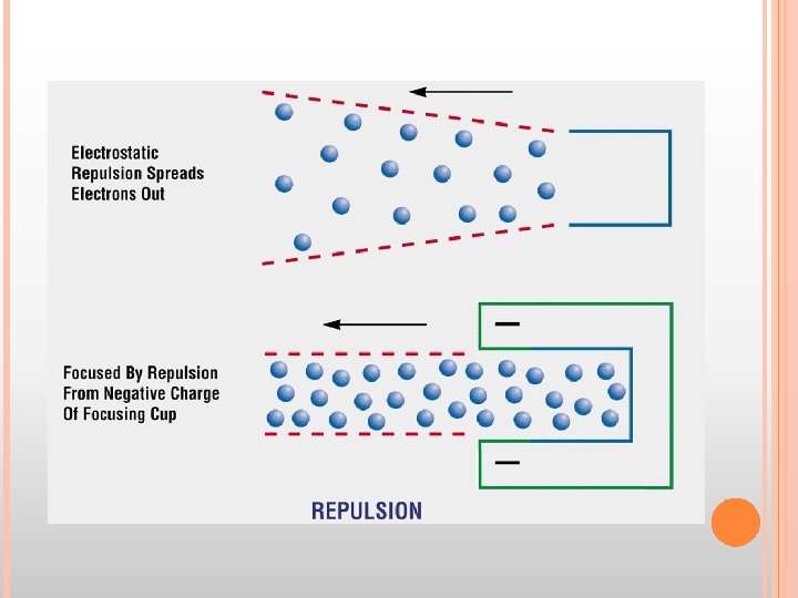
FOCUSING CUP: Ø Ø Ø Made of Nickel. Maintained at the same –ve potential as the filament Causes the electrons to converge on the target anode in required size & shape

CONNECTING WIRES: Ø Supplies the voltage & amperage i. e the current needed to heat the filament. Ø Tube Current is defined as the no. of elec. Flowing per second from the filament to the target (measured in milliamperes, m. A). Ø Electron current across the tube is in one direction only.

THERMIONIC EMISSION: Ø When current flows the filament becoms heated, some atoms absorb sufficient thermal energy to allow them to move from the surface of the metal. Ø This emission of electrons resulting from the absorbtion of thermal energy is called THERMIONIC EMISSION.

SPACE CHARGE: As a result of thermionic emission small cloud of electrons around the filament , this is called as the SPACE CHARGE. Ø As it is made of negatively charged elec. It prevents other electrons from being emitted from the filament , this is called as the SPACE CHARGE EFFECT. Ø

SATURATION VOLTAGE:

ØTungsten vaporized from the filament gets deposited on the inner side of the glass wall : becomes bronze coloured SUN BURN Ø This has two effects: -filter the x-ray beam, gradually changing the quality of the beam. -presense of metal on the glass surface causes arcing at high peak voltage.

ANODE: Ø It is the +ve electrode. 2 types Stationary Rotating

FOCAL Ø SPOT: It is the area of the anode/tungsten which is bombarded by the electrons. Ø Most of the energy is converted into heat, <1% into X-Rays.

ØLarge focal spot allows for accumulation of large amounts of heat before damage to the tungsten target occurs. ØSmaller the focal spot, better is the resolution of the resultant image.

LINE FOCUS PRINCIPLE: It resolved the problem posed by the need of: -A large focal spot for better heat loading & -Small focal spot need for good radiographic details

By angling the target, the effective area of the target is much smaller than the actual area of electron interaction

TARGET ANGLE: Ø The smaller the target angle the smaller the effective focal spot Ø Angles from 5 degrees to 15 degrees

STATIONARY ANODE: Made of tungsten , 2 -3 mm thick Ø Embedded in a large mass of copper. Ø Square or rectangular in shape. Ø Anode angle : 15 -20 degrees. Ø

ØTungsten is a good material for absorption & rapid dissipation of heat away from the target area. ØLarge block of copper is bound to tungsten plate to - increase the total thermal capacity of the anode - Speed its rate of cooling. As Cu is a better conductor of heat & tungsten cannot withstand heat of repeated exposures.

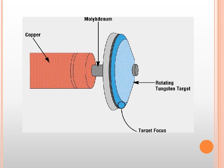
ROTATING ANODE: Ø Used to produce X-ray tubes capable of withstanding heat generated by large exposures.

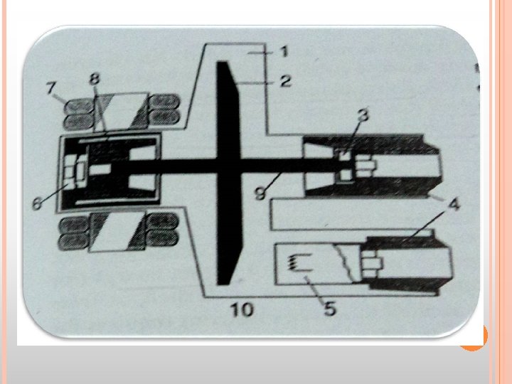
Ø Made of large disc of tungsten which rotates at speed of 3600 rpm theoretically when the exposure is being made(in prac. reaches ard 3000 rpm). Ø The disc has beveled edges(to take advantage of the Line Focus Principle) Ø Power of rotation is provided by magnetic field produced by stator coils that surround the neck of the X-Ray tube outside the envelope , which induce current in the copper rotor of the induction motor which rotates the anode assembly.

Ø If the target is made to rotate , electrons will bombard constantly changing area of the target. Ø If it is rotating at the speed of 3600 rpm , then any given area is found opp. the elec. stream only once every 1/60 th sec , the remainder time used for heat dissipation.
 Life of the tube reduces coz of lack of durable bearings on")
SHORTCOMINGS: I) Life of the tube reduces coz of lack of durable bearings on which the anode rotates. Because of the friction it is necessary to lubricate : commonly used lubricants cannot be used -Oil : vaporizes & destroys the vaccum. - Graphite : wear off as powder & destroy the vaccum. METALLIC SILVER IS USED
Heat dissipation : - In Statinary : Cu block -In rotating : absorption of")
II)Heat dissipation : - In Statinary : Cu block -In rotating : absorption of heat by anode assembly undesirable as heat expand bind , the bearings. SOLUTION: 1) Molybdenum stem. -High melting point(2600 deg. ) -poor conductor of heat Hence , it acts as a barrier of heat. If length , inertia , load , hence keep the stem as short as possible.

ØAnother way to dec inertia : dec. the weight of the anode itself. ØLarger part of the disc to be made of molybdenum(lighter) : 35% reduction in the inertia. ØGraphite can also be used : 50% reduc. but problem with it – doesn’t conduct heat like molyb. So the anode assembly becomes hotter. - problem in binding the tungsten disc to graphite.
 Coating the back of the anode disc with a black substance , such")
2) Coating the back of the anode disc with a black substance , such as carbon , to aid in heat dissipation from the anode. III) Red. life by roughening & pitting of the surface : by thermal stress : decreases output coz of a) excess scattering away frm the exit window. b) Increased absorption of the x-rays by the target itself.

ANODE HEEL EFFECT: INTENSITY OF THE X-RAY BEAM THAT LEAVES THE TUBE IS NOT UNIFORM THROUGHOUT ALL THE PORTIONS OF THE BEAM. It depends on the angle at which the x-rays are emitted from the focal spot ; this variation is called HEEL EFFECT

Ø There is decreased intensity of the beam that is emitted more near parallel to the angled target surface. Ø Caused by the absorption of some of the photons by the anode itself.
Intensity of film exposure is less on")
3 clinically imp aspects of Heel Effect: 1)Intensity of film exposure is less on the anode side compared to the cathode side ; used in obtaining balanced densities in radiographs: - thicker parts: towards cathode side -thinner parts : towards the anode side Ex: Thoracic spine –anode towards the upper th. Spine & cathode towards the lower spine where the body structures are thicker.

ANODE HEEL EFFECT
 Heel Effect is less noticable when a large film-focus distance is used. At")
2) Heel Effect is less noticable when a large film-focus distance is used. At a distance of 40” : anode end –relative exposure of 73% cathode end – 105% Hence 30% difference in intensity between the two ends. At 72 cms : anode end-87% cathode end-104% Hence, only 17% diff in intensities between the two ends.
 Heel effect will be less for smaller films : as intensity of the")
3) Heel effect will be less for smaller films : as intensity of the beam nearer the central ray is more uniform than towards the periphery of the beam.

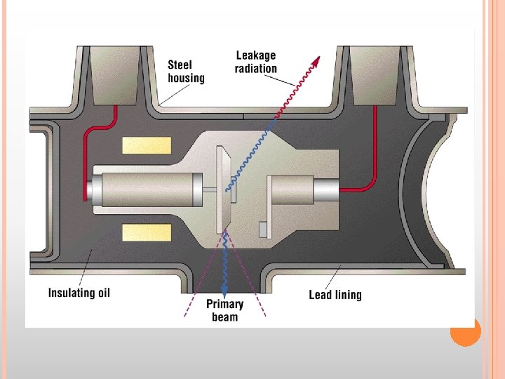
TUBE HOUSING:

Ø Protects from the radiation. ØPrevents excess film fogging. ØAlso provides shielding for the high voltage cables required to produce xrays. ØThese cables are grounded. ØTo prevent short circuiting , space between the tube & cables if filled with thick mineral oil.

ØOil has – electrical insulating & - thermal cooling properties. Convection currents set up in the oil which carry the heat away frm the tube to the metal surface frm where heat is lost by conduction. ØOil expands on heating, metal bellows are present: which allow oil to expand without incresing the pressure , connected to microswitch, which prevent further exposure if max. heating of oil has occurred.

GRID – CONTROLLED X-RAY TUBES: Ø It’s a tube which contains its own ‘switch’ which allows it to turned on & off rapidly. Ø A 3 rd electrode is used which controls the flow of electrons from the filament to the target. Ø It is actually the focusing cup. Ø The focusing cup counteracts the flow of electrons.

Ø If the voltage of cup is made large enough , tube current may be completely pinched off , where no electrons go to the target Ø The voltage applied between the focusing cup & the filament therefore acts like a SWITCH.

METALLIC/CERAMIC X-RAY TUBES: Ø Introduced by Philips with a trade name of ceramic super Rolatix. Ø Difference: a) Metal casing instead of usual glass. b) Has 3 ceramic insulators(2 for the high vol cables & 1 for anode stem). Aluminum oxide used mostly. c) Anode rotates on an axle which has bearings at each end.
 Less Off-focus radiation. 2) Longer tube life. 3) Higher tube loading.")
ADVANTAGES: 1) Less Off-focus radiation. 2) Longer tube life. 3) Higher tube loading.

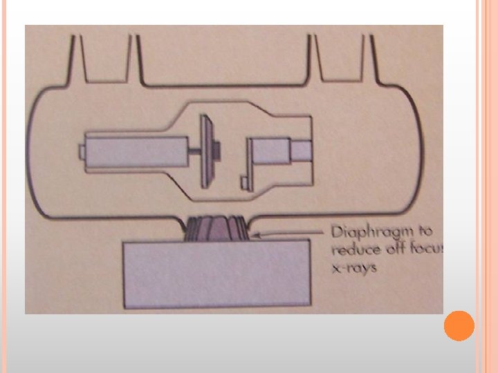
OFF-FOCUS RADIATION: Produced when electrons interact with metal surfaces other than the focal track of the anode. Ø Main source is back scatter from anode. Ø Partly reduced by placing the collimator or a lead diaphragm as close to the tube as possible. Ø

ØMetal tube decreases off- focal radiations by attracting the –vely charged electrons to the grounded metal wall. ØMetal enclosure which is at a zero potential(since it is grounded) , is relatively +ve as compared to the electrons. ØElectrons striking the metal wall may produce x-rays , but the low atomic no. metal wall produces few & low energy xrays.

LONGER TUBE LIFE: Ø Deposition of tungsten on the glass wall decreases tube life as it causes arcing between the glass & filament by acting as an anode itself. Ø Metal enclosure is grounded , hence deposition of tungsten will not alter this grounding. Ø For this reason tube life will be greater especially when used for high tube currents.
 allows for")
HIGH TUBE Ø LOADING: The more massive anode (coz of extra bearings) allows for higher tube current & increased capacity for serial exposures coz of : -larger heat storage capacity. -better cooling.

TUBE RATING CHARTS: The limit on the load(in terms of Kv , m. A & exposure time) that can safely be accepted by an x-ray tube is a function of heat energy produced during the exposure. This energy is currently expressed in two different systems: Heat Units (an artificial system) SI units (the watt-second or joule)

HEAT UNITS: Heat Unit is defined as product of m. A and Kvp and time(sec) for a single phase power supplies. It is expressed as HU. For single phase generator: 1 HU = 1 Kvp x 1 m. A x 1 sec For modern triple phase generator( which we routinely use) 1 HU = 1. 4 x 1 k. Vp x 1 m. A x 1 sec Since kvp=1. 4 x Kv(i. e average voltage)
 2) 3) Radiographic rating charts. Anode cooling")
3 types of tube rating charts: 1) 2) 3) Radiographic rating charts. Anode cooling charts. Housing cooling charts.

RADIOGRAPHIC Ø This RATING CHARTS: is the most important of the three charts Ø It conveys which radiographic exposures are safe and which are unsafe Ø The chart shows a family of curves for different m. A Ø For a given m. A, any combination of k. Vp and time that lies below the curve is safe Ø Any combination that lies above the curve of desired m. A is unsafe

Is used for Single exposure. Can be used for Multiple rapid exposures ( i. e. angiography) though however special charts are available
 The ability of")
Three characteristics are to be considered for tube rating charts: 1) The ability of the tube to withstand single exposure. 2) Multiple rapid exposures( as in angiography) 3) Multiple exposures during several hours of heavy use (Fluoroscopy)

ANGIOGRAPHIC CHART

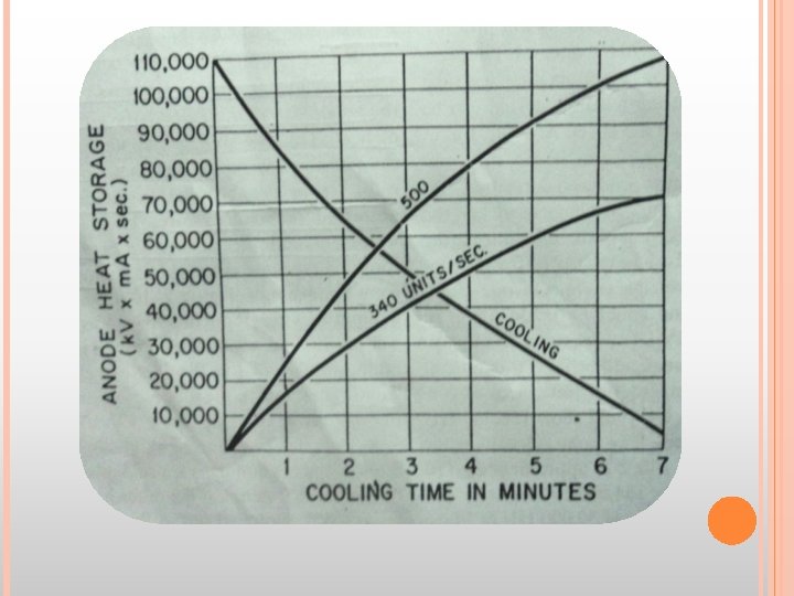
ANODE COOLING CHARTS: Ø Anode cooling charts contain the information about thermal capacity of an anode and its heat dissipation characteristics. Ø It is used to determine the length of time required for complete cooling after any level of heat input.

HOUSING Ø The COOLING CHARTS: cooling chart for the housing of the x-ray tube has a similar shape as the anode cooling chart. Ø The maximum heat capacity of the housing is in the range of several million heat units. Ø Complete cooling after maximum heat capacity requires from 1 to 2 hours

MICROFOCUS X-RAY TUBES: x-ray tubes that generate very small focal spot size , upto 50µ , even smaller than 1µm may be produced. Ø 2 types: - Solid anode tube - Metal jet anode tubes Ø Solid Anode tube : focuses electron beam into very small spot at the anode. Major disadv: It operates at a very low power(4 -8 W) in order to avoid melting of the anode. Ø

Ø Metal Jet Anode Microfocus Xray tube: Here the solid metal anode is replaced by a jet of liquid metal which acts as a target. Advantage : Maximun power density increases(30 -60 W). Used in XRD , XRF(methods of NDT)

THANK YOU !!!
- Slides: 83