X BY WIRE X by Wire Krishna Suman

X BY WIRE X by Wire Krishna Suman Kadiyala Fault Tolerant Systems EE 585 Fall 2006 Krishna Suman Kadiyala EE 585 001 Fault Tolerant Computing

OUTLINE X By Wire n Time Triggered Approach n Steer by wire prototype n Fault Tolerance in Steer By Wire n

What is X by Wire? Ultra dependable electronic systems in vehicles n Do not rely on conventional physical backups n "x" represents the basis of any safety related application n More cost efficient n Increase overall vehicle safety n Less pollution n
 n")
General Architecture A microcomputer with its local memory n A communication controller (CC) n A process interface (I/O interface) n Communication network interface (CNI). n

Example of a distributed system

Time triggered Approach § TIME TRIGGERED APPROACH Intended applications of X by wire systems - Periodically read system states - Calculate new intended system states - Forward the results § All system activities are initiated by the progression of a globally synchronized time. § Periodic messages are transported in state-message semantics

Advantages of Time Triggered Architecture Composability n Babbling idiot avoidance n Certification Issues n

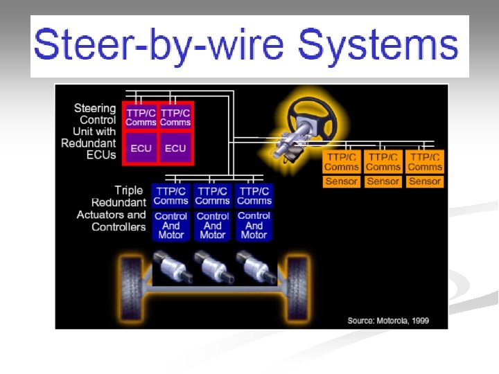
Steer by wire Prototype

Principal of Application Driver Intention Torque Feedback 9

Function Walk through Feedback Torque is based on: • Simulated : Automatic straight run Vehicle behaviour • Angular End Stop Controller • Torque from Road Wheels Cruise Switch SW_Angle Output Steering Control consists of: • Initial alignment of Steering Wheel and Road Wheels • PID controller Vehicle Velocity SBW_Ctrl Feedback Control S_Control Output Monitor S_Torque Monitor Steering Wheel FTU S_Angle Steer-By-Wire Control FTU Steering FTU 10

Function Walk through Cruise Switch SW_Angle Outpu t Vehicle Velocity SBW_Ctrl Feedback Control S_Control Outpu t Monitor S_Torque Monitor Steering Wheel FTU S_Angle Steer-By-Wire Control FTU Steering FTU 11

Steer-By-Wire System Communication Subsystem Steering Wheel FTU MONITOR & FAULT INJECTION asw TTP/C Bus as w usw Steering Wheel FTU • 2 Nodes, us w Steering Wheel FTU • 1 TTP/C controller per node • 2 TTP/C buses. as us Is • 4 Angle sensors, Steer-By-Wire Control FTU Steering FTU Diagnostics Node • 2 Feedback Actuators. 100% torque per TTP/C Bus actuator. Future. Steer-By-Wire Control FTU Power Supply Steer-By-Wire Functionality: Control • 2 Nodes FTU ² Collision Avoidance ² Vehicle Stability Control ² Side Wind Compensation 12

Power Supply Steer-By-Wire System Batteries, • 3 “Diagnostic Node” • 3 Power Supply boards, • 1 Battery charger • 1 Steering Industrial FTU (emulates. PC, an alternator) Power Supply MONITOR & FAULT INJECTION Monitor of abuses: u a I u • 3 Nodes, • 1 TTP/C Steering controller on a Steer-By-Wire Wheel Steering Control FTU FTU • PCI-40 3 Angleboard, sensors with Faultdouble Injection: TTP/C Bus sensing elements, • 1 PC-DIO-24 board, • 2 • External relay boxes connected Power Supply 3 Actuators with current to TTP/C buses and power monitoring, supply. 50% torque per actuator, s sw w Diagnostics as u I s s s Diagnostics Node Steering FTU • 3 Torque sensors. 13

Sensor and actuator architecture Redundant sensors n Different physical principles n Fail silent actuators n

Communication System § § Communication between the nodes of a distributed time-triggered architecture is performed using the Time-Triggered Protocol TTP/C C stands for SAE class C. Communication network topology is a broadcast bus Bus access is granted to the nodes under the control of a static TDMA scheme.

TTP Databus System

TTP/C n TTP is an integrated time-triggered protocol that provides: a membership service a fault-tolerant clock synchronization mode change support error detection with short latency distributed redundancy management

Fault Tolerance in Communication system n Error Detection Bit Stuffing n CRC n ACK n

System Software Architecture Based on DFR model: Value Domain Time Domain Distribution Domain n

Orthogonal Coding n Like N-version but intentional variation Same computation through different algorithms n Catches software and hardware failures n May be done as complex/unreliable and simple/reliable algorithms n May be less than 2 X overhead n

Memory Testing n ROM integrity n n RAM integrity n n n Program and other static data Can only verify correctness Use checksum or CRC Need to verify correct read and write Use techniques from test community Online or Offline n n Detect latent failures Test every 10 to 100 hours

Handling Exceptional Conditions n Software Watchdog Programmable timeout n Partial Amnesia n Breaks deadlock n n Assertions Programmer uses knowledge of invariants n Will catch some software bugs and hardware faults n

REFERENCES TECHNICAL REPORT ON X BY WIRE n CONTROL DESIGN FOR X BY WIRE COMPONENTS C. CANUDAS n

QUESTIONS? ? ? ?
- Slides: 25