
x 86 Protected Mode Marius Vana mvantabitdefender com

x 86 Protected Mode Marius Vanța mvanta@bitdefender. com
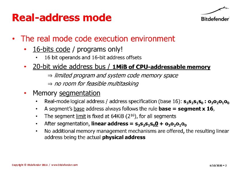
Real-address mode • Copyright © Bitdefender 2019 / www. bitdefender. com 9/10/2020 • 2
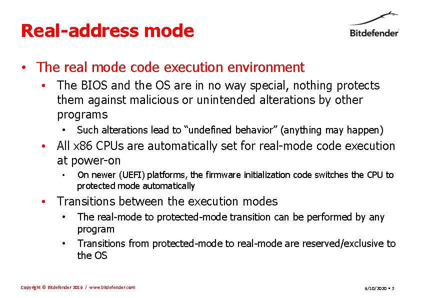
Real-address mode • The real mode code execution environment • The BIOS and the OS are in no way special, nothing protects them against malicious or unintended alterations by other programs • Such alterations lead to “undefined behavior” (anything may happen) • All x 86 CPUs are automatically set for real-mode code execution at power-on • On newer (UEFI) platforms, the firmware initialization code switches the CPU to protected mode automatically • Transitions between the execution modes • • The real-mode to protected-mode transition can be performed by any program Transitions from protected-mode to real-mode are reserved/exclusive to the OS Copyright © Bitdefender 2019 / www. bitdefender. com 9/10/2020 • 3
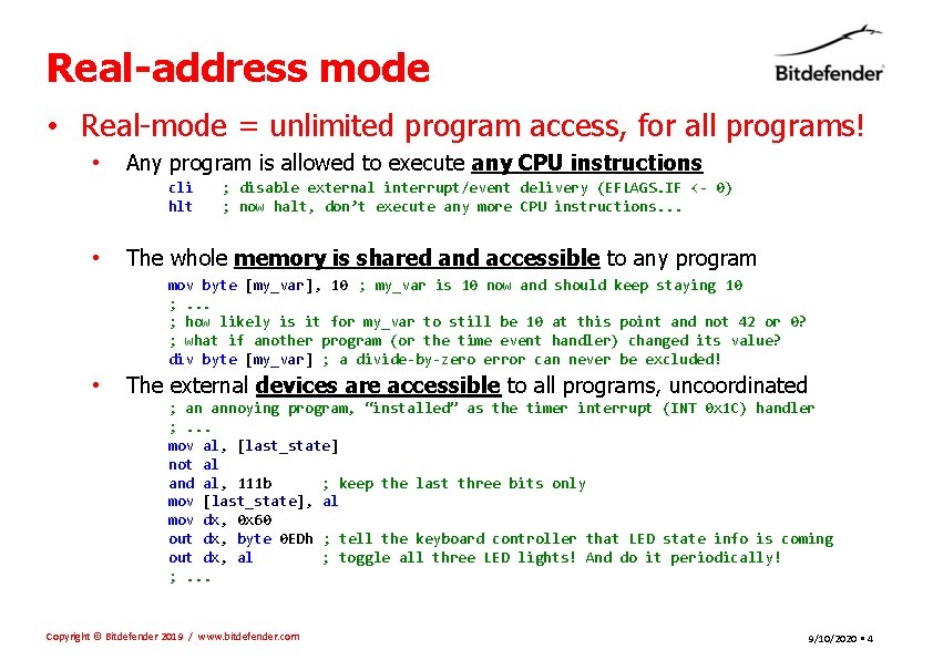
Real-address mode • Real-mode = unlimited program access, for all programs! • Any program is allowed to execute any CPU instructions cli hlt • ; disable external interrupt/event delivery (EFLAGS. IF <- 0) ; now halt, don’t execute any more CPU instructions. . . The whole memory is shared and accessible to any program mov byte [my_var], 10 ; my_var is 10 now and should keep staying 10 ; . . . ; how likely is it for my_var to still be 10 at this point and not 42 or 0? ; what if another program (or the time event handler) changed its value? div byte [my_var] ; a divide-by-zero error can never be excluded! • The external devices are accessible to all programs, uncoordinated ; an annoying program, “installed” as the timer interrupt (INT 0 x 1 C) handler ; . . . mov al, [last_state] not al and al, 111 b ; keep the last three bits only mov [last_state], al mov dx, 0 x 60 out dx, byte 0 EDh ; tell the keyboard controller that LED state info is coming out dx, al ; toggle all three LED lights! And do it periodically! ; . . . Copyright © Bitdefender 2019 / www. bitdefender. com 9/10/2020 • 4
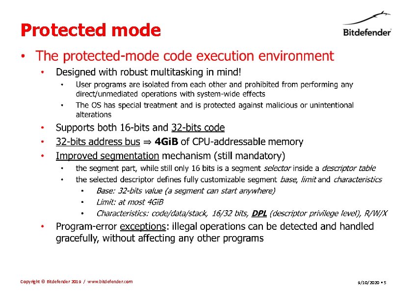
Protected mode • Copyright © Bitdefender 2019 / www. bitdefender. com 9/10/2020 • 5
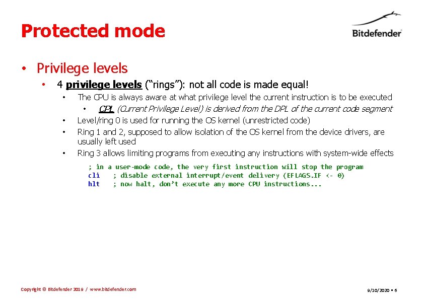
Protected mode • Privilege levels • 4 privilege levels (“rings”): not all code is made equal! • • The CPU is always aware at what privilege level the current instruction is to be executed • CPL (Current Privilege Level) is derived from the DPL of the current code segment Level/ring 0 is used for running the OS kernel (unrestricted code) Ring 1 and 2, supposed to allow isolation of the OS kernel from the device drivers, are usually left used Ring 3 allows limiting programs from executing any instructions with system-wide effects ; in a user-mode code, the very first instruction will stop the program cli ; disable external interrupt/event delivery (EFLAGS. IF <- 0) hlt ; now halt, don’t execute any more CPU instructions. . . Copyright © Bitdefender 2019 / www. bitdefender. com 9/10/2020 • 6
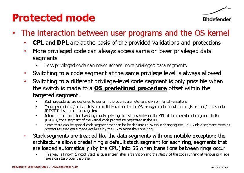
Protected mode • The interaction between user programs and the OS kernel • • CPL and DPL are at the basis of the provided validations and protections More privileged code can always access same or lower privileged data segments • • • Switching to a code segment at the same privilege level is always allowed Switching to a different privilege-level code segment is only possible when the switch is made to a OS predefined procedure offset within the targeted segment. • • • Less privileged code can never access more privileged data segments Such procedures are designed to perform thorough parameter and environmental validations These procedures / entry points are explicitly defined by the OS through a set of dedicated registers and/or as special IDT/GDT descriptors called gates Interrupt and exception handling require privilege transitions between the CPL of the current code segment to the (DPL=0) code segment of the kernel code procedure registered in the IDT Note: there can be special code segment that can be loaded into CS without changing the CPL! Such a segment contains procedures that were made available by the OS to more than one ring. Stack segments are treaded like the data segments with one notable exception: the architecture allows predefining a default stack segment for each ring, segments that are loaded automatically (by the CPU) into SS when transitions between rings occur • This way, a known (&good) stack is guaranteed after a transition and the stacks of the code running at various privilege levels can be properly isolated Copyright © Bitdefender 2019 / www. bitdefender. com 9/10/2020 • 7
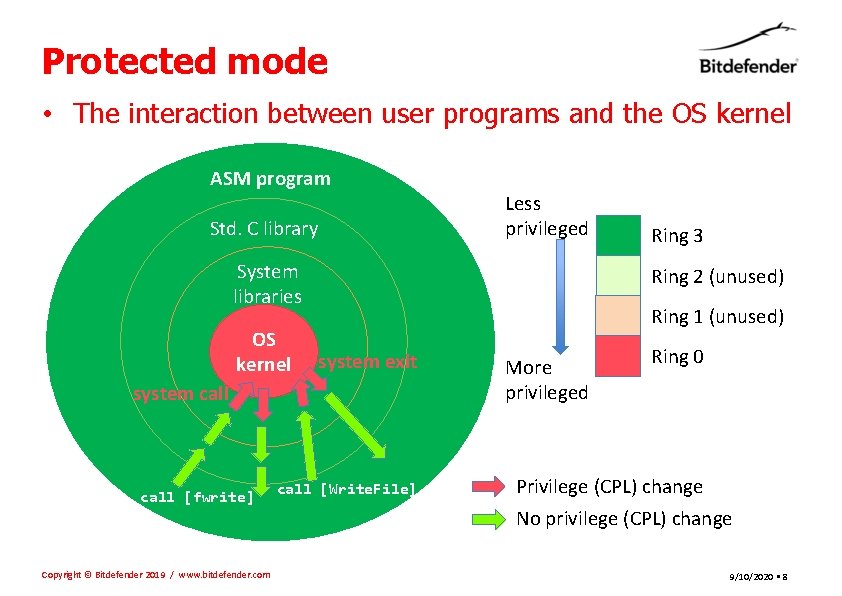
Protected mode • The interaction between user programs and the OS kernel ASM program Std. C library Less privileged System libraries OS kernel Ring 2 (unused) Ring 1 (unused) system exit system call [fwrite] Copyright © Bitdefender 2019 / www. bitdefender. com Ring 3 call [Write. File] More privileged Ring 0 Privilege (CPL) change No privilege (CPL) change 9/10/2020 • 8
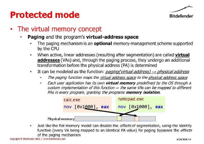
Protected mode • calc. exe mov [0 x 1000], eax notepad. exe mov [0 x 1000], eax Physical memory Copyright © Bitdefender 2019 / www. bitdefender. com 9/10/2020 • 9
Protected mode • The virtual memory concept • Paging and the program’s virtual-address space • The actual associations (between VAs and their corresponding PAs) performed by the paging mechanism is defined by the system software through x 86 architecturally-defined data structures named hierarchical paging structures • If we were to consider defining the mappings on a byte-by-byte basis, the volume of necessary data would be impractically large! For this reason, a coarser granularity known as a page size is used and the smallest block of continuous memory individually configurable through paging is called a memory page. • • A pair of VA and PA associated through the paging mechanism are always of the same size and both start at an address that’s a multiple of (are aligned to) page size Some technical details regarding the paging structures and how they function • There are multiple paging modes with different features and (slightly) different data structures! The actual paging structures are composed of a hierarchy of page tables structured as a multiway tree with a depth of N (between 1 and 4). Every page table is 4 Ki. B in size and has 512 or 1024 entries (QWORDs or DWORDs) The highest bits of an input VA are split into N components that are used as indices inside the page tables for traversing the tree. The final entries in the leaf-nodes / tables do not link to yet another page table but instead to the actual physical page associated with the entire input virtual page The lowest address bits (that were not used as indices) are used as an offset inside the page • The table entries encode both the address translation and access restrictions too! • • • Copyright © Bitdefender 2019 / www. bitdefender. com 9/10/2020 • 10
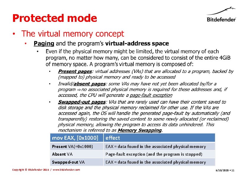
Protected mode • mov EAX, [0 x 1000] effect Present VA(=0 x 1000) EAX = data found in the associated physical memory Absent VA Page-fault exception (and the program is stopped) Swapped-out VA EAX = data found in the associated physical memory Copyright © Bitdefender 2019 / www. bitdefender. com 9/10/2020 • 11
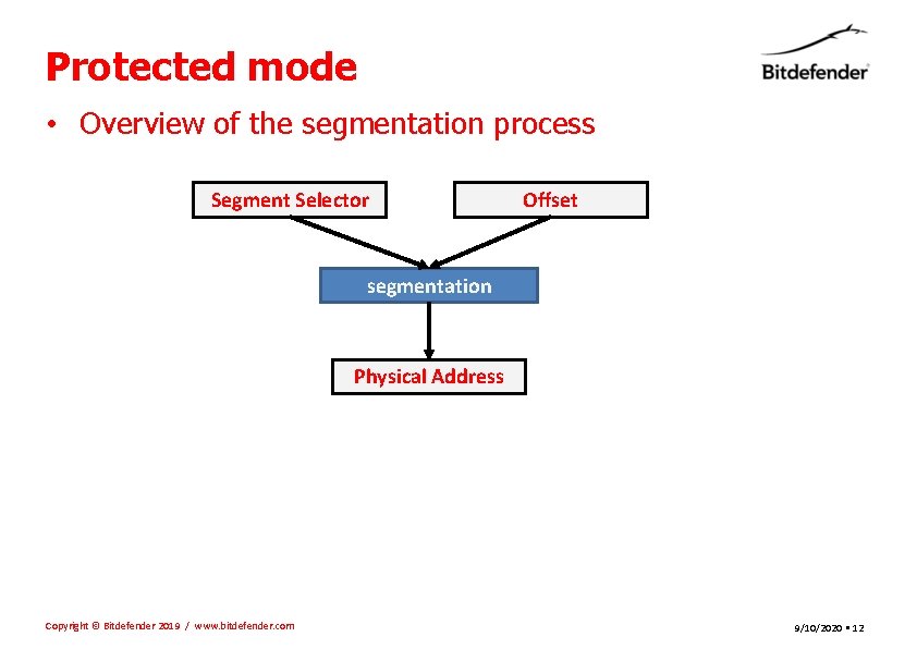
Protected mode • Overview of the segmentation process Segment Selector Offset segmentation Physical Address Copyright © Bitdefender 2019 / www. bitdefender. com 9/10/2020 • 12
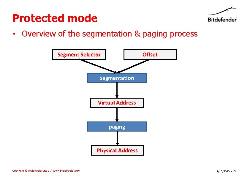
Protected mode • Overview of the segmentation & paging process Segment Selector Offset segmentation Virtual Address paging Physical Address Copyright © Bitdefender 2019 / www. bitdefender. com 9/10/2020 • 13
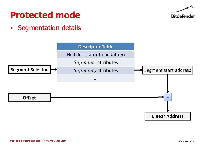
Protected mode • Segmentation details Descriptor Table Null descriptor (mandatory) Segment Selector Segment start address … Offset + Linear Address Copyright © Bitdefender 2019 / www. bitdefender. com 9/10/2020 • 14
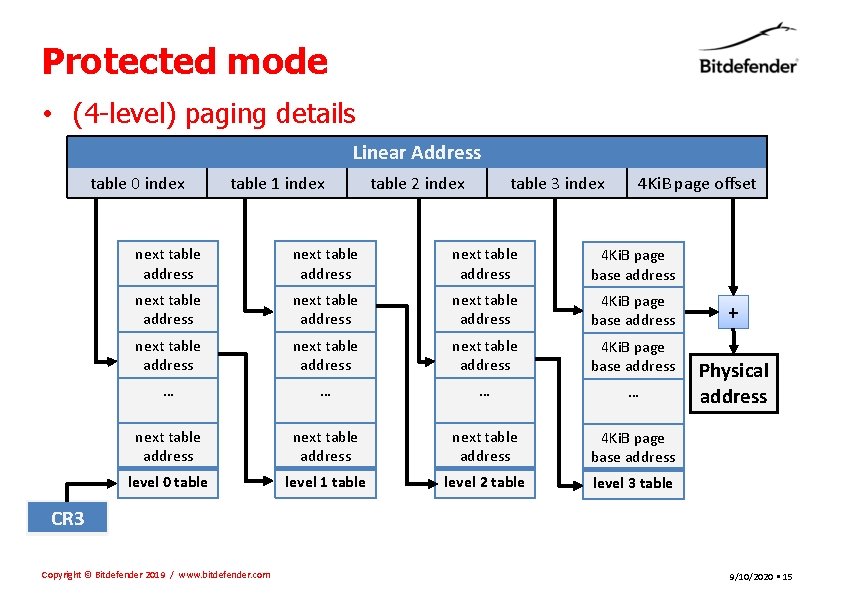
Protected mode • (4 -level) paging details Linear Address table 0 index table 1 index table 2 index table 3 index 4 Ki. B page offset next table address next table address 4 Ki. B page base address next table address 4 Ki. B page base address … … next table address 4 Ki. B page base address level 0 table level 1 table level 2 table level 3 table + Physical address CR 3 Copyright © Bitdefender 2019 / www. bitdefender. com 9/10/2020 • 15
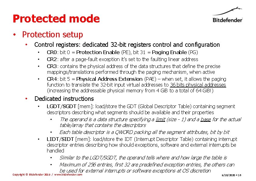
Protected mode • Protection setup • Control registers: dedicated 32 -bit registers control and configuration • • • CR 0: bit 0 = Protection Enable (PE), bit 31 = Paging Enable (PG) CR 2: after a page-fault exception it’s set to the faulting linear address CR 3: contains the physical address of the data structures that define the precise mappings/translations performed through the paging mechanism, when active CR 4: bit 5 = Physical Address Extension (PAE) – when set, it allows the paging function to translate the 32 -bit input virtual addresses to 36 bits physical addresses (increasing the addressable physical memory from 4 Gi. B to a total of 64 Gi. B!) Dedicated instructions • LGDT/SGDT [mem]: load/store the GDT (Global Descriptor Table) containing segment descriptors describing what segments should be available and their properties • The operand is a data structure specifying a limit (size - 1) and a base for the actual table/array that contains the descriptors Each table descriptor is a QWORD packing all the segment attributes, bit by bit • • LIDT/SIDT [mem]: load/store the IDT (Interrupt Descriptor Table) containing interrupt descriptor entries describing how should exceptions, software and external interrupts be handled • Similar to the LGDT/SGDT, the operand tells where and how large the table is • Maximum of 256 entries, first 32 are predefined exception entries, the others can be used for external interrupts or software exceptions at OS discretion Copyright © Bitdefender 2019 / www. bitdefender. com 9/10/2020 • 16
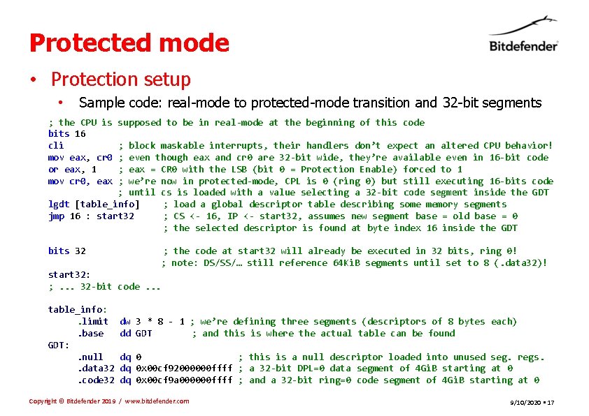
Protected mode • Protection setup • Sample code: real-mode to protected-mode transition and 32 -bit segments ; the CPU is bits 16 cli mov eax, cr 0 or eax, 1 mov cr 0, eax supposed to be in real-mode at the beginning of this code ; block maskable interrupts, their handlers don’t expect an altered CPU behavior! ; even though eax and cr 0 are 32 -bit wide, they’re available even in 16 -bit code ; eax = CR 0 with the LSB (bit 0 = Protection Enable) forced to 1 ; we’re now in protected-mode, CPL is 0 (ring 0) but still executing 16 -bits code ; until cs is loaded with a value selecting a 32 -bit code segment inside the GDT lgdt [table_info] ; load a global descriptor table describing some memory segments jmp 16 : start 32 ; CS <- 16, IP <- start 32, assumes new segment base = old base = 0 ; the selected descriptor is found at byte index 16 inside the GDT bits 32 ; the code at start 32 will already be executed in 32 bits, ring 0! ; note: DS/SS/… still reference 64 Ki. B segments until set to 8 (. data 32)! start 32: ; . . . 32 -bit code. . . table_info: . limit. base GDT: . null. data 32. code 32 dw 3 * 8 - 1 ; we’re defining three segments (descriptors of 8 bytes each) dd GDT ; and this is where the actual table can be found dq 0 ; this is a null descriptor loaded into unused seg. regs. dq 0 x 00 cf 92000000 ffff ; a 32 -bit DPL=0 data segment of 4 Gi. B starting at 0 dq 0 x 00 cf 9 a 000000 ffff ; and a 32 -bit ring=0 code segment of 4 Gi. B starting at 0 Copyright © Bitdefender 2019 / www. bitdefender. com 9/10/2020 • 17

- Slides: 18