Working Drawings Production Drawings Xinli Wu The Penn
 Xinli Wu The Penn State University")


 all the parts, drawn")


- Slides: 17
Working Drawings (Production Drawings) Xinli Wu The Penn State University
Objectives • Define working drawings • Describe how working drawings are used in industry • List the major components of a complete set of working drawings • Describe the difference between detail and assembly drawings
1. Introduction • Working drawings are specialized engineering drawings that provide information required to make the part or assembly of the final design. • Working drawings rely on orthographic projection and many other graphical techniques to communicate design information for production.
2. Definition of Working Drawings • The drawings from which a design is built; • Are legal contacts that document the design details and specifications.
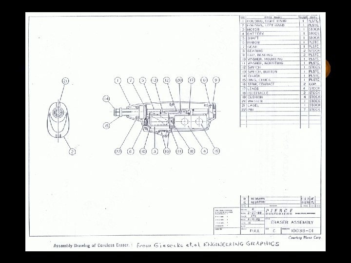
Major components of a complete set of working drawings: • An assembly or subassembly drawing showing all the standard and nonstandard parts in a single drawing. • Detail drawing of each nonstandard part. • A bill of material (BOM)-- parts list. • A title block.
3. Assembly Drawing • An assembly drawing shows how each part of a design is put together. (If a design depicted is only part of a total assembly, it is referred to as a subassembly. )
-- continued • Components in an assembly drawing includes: (1) all the parts, drawn in their operating position; (2) A parts list or bill of materials (BOM); (3) leader lines with balloons, assigning each part a detail number, in sequential order; (4) machining and assembly operations and critical dimensions related to those functions.
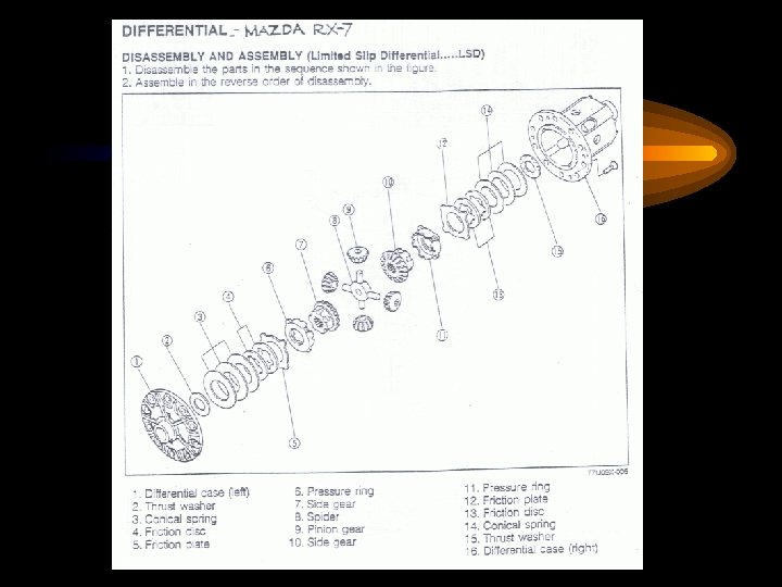
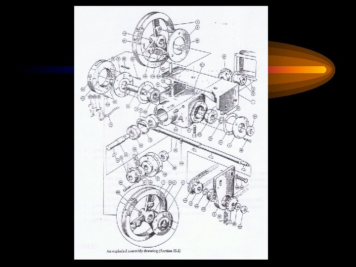
-- continued • Assembly drawings maybe pictorial drawings or orthographic drawings • Assembly drawings maybe exploded or not. Exploded assembly drawings show the parts pulled apart but they still line up.
4. Parts List • Consists of an itemized list of all the parts to assemble one complete unit • Contain the following: (1) part number (2) part name (3) number of parts req’d (4) material (5) description
-- continued • Parts list placed above the title block should be read from the bottom to the top • Parts list placed at the top of a sheet should be read from top to bottom • Position of the parts list is your choice
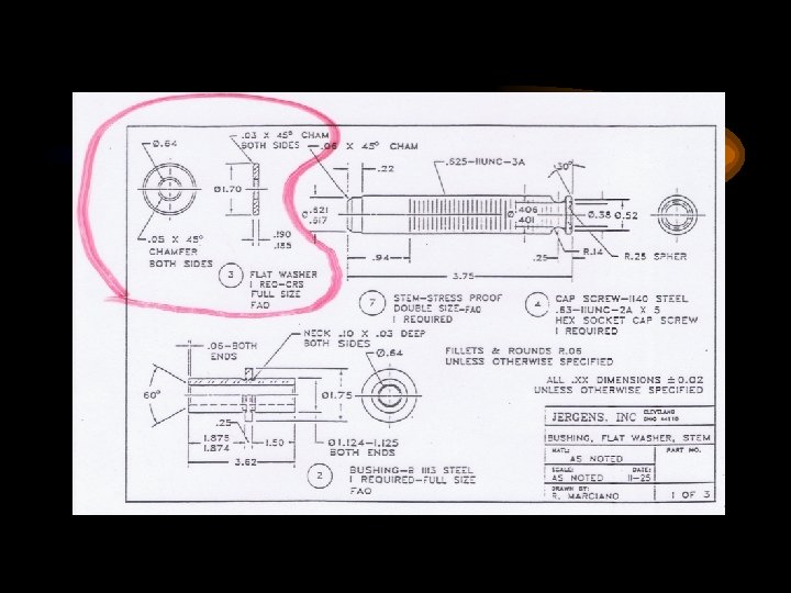
5. Detail Drawings • Each nonstandard part will receive a detail drawing showing how the part looks when completed. • It completely describe the part giving everything one needs to make it, including shape, size, material, finish.
-- continued • The part number followed by the part name is given below each detail drawing. • Detail drawings are not needed for standard parts such as screws, threaded fasteners, bushing, bearings.
THANK YOU!