Work Distribution Analysis of I C Engine Cycles

Work Distribution Analysis of I. C. Engine Cycles P M V Subbarao Professor Mechanical Engineering Department Find true Scope for Development….

BSFC of the 4 - and 5 -stroke engines at 4000 rpm

Fuel economy of the 5 -stroke cycle vs. 4 -stroke cycle The 750 ccm five-stroke engine is designed to produce equivalent torque/power, i. e. 46 k. W/110 Nm at 4000 rpm, than the 1200 ccm fourstroke engine.

The Model Four Stroke Engine Number of cylinders: 4 Supercharged: No Global piston displacement: 1202 cc Individual piston displacement: 300. 5 cc Bore: 72. 6 mm Stroke: 72. 6 mm Compression ratio: 10: 1 Number of intake valves: 1 Intake valve, diameter: 26 mm Number of exhaust valves: 1 Exhaust valve diameter: 26 mm

Work Distribution Analysis of Conventional S. I. Engine Indicative Cycle at Design Conditions • • • Work transfer during intake process: 25. 6 J Work transfer during compression process: -102. 7 J Work transfer during Expansion process: 487. 9 J Work transfer during Exhaust process: -37. 6 J Net Indicative work per cycle : 373. 2 J Heat Input (J): 943. 0 J

Energy Audit of Conventional S. I. Engine Indicative Cycle at Design Conditions • • • Net Indicative work per cycle : 373. 2 J Heat Input (J): 943. 0 J & Total cooling loss -187. 3 J Heat transfer density (W/cm²) at. . . cylinder head: -45. 168. . . piston upper face: -42. 378. . . cylinder wall: -14. 228 Effective torque (Nm): 110. 0 Effective power (k. W): 46. 1 Thermodynamic efficiency (. /. ): 0. 39577 Mechanical efficiency (. /. ): 0. 926 Global efficiency (. /. ): 0. 366 BSFC (gr/k. Wh): 229. 6
 Cycle")
Work Distribution Analysis of Conventional S. I. Engine (Indicative) Cycle

The Model Five Stroke Engine • • • • Number of cylinders: 3 Supercharged: Yes Global piston displacement: 750 ccm High pressure area (HP): Number of cylinders: 2 Individual piston displacement: 150 ccm Bore: 60 mm Stroke: 53 mm Compression ratio: 8: 1 Number of intake valves: 1 Intake valve, diameter: 21 mm Number of exhaust valves: 1 Exhaust/Transfer valve diameter: 21 mm
: Number of cylinders: 1 Individual piston displacement:")
• • Low pressure area (LP): Number of cylinders: 1 Individual piston displacement: 449 ccm Bore: 83 mm Stroke: 83 mm Compression ratio: 7. 7: 1 Number of exhaust valves: 1 Exhaust valve diameter: 45 mm

Work Distribution Analysis of Five Stroke S. I. Engine Indicative Cycle at Design Conditions : HP Cylinder • • • Work transfer during intake process: 51. 3 J Work transfer during compression process: -158. 4 J Work transfer during Expansion process: 732. 7 J Work transfer during Exhaust process: -94. 2 J Net Indicative work per cycle : 531. 5 J

Work Distribution Analysis of Five Stroke S. I. Engine Indicative Cycle at Design Conditions : LP Cylinder • • • Work transfer during Expansion process: 348. 2 J Work transfer during Exhaust process: -147. 5 J Net Indicative work per cycle : 200. 3 J Total indicated work (J): 731. 9 Heat Input (J): 1582. 8

Indicated work over two crank rotations in the 5 stroke engine

Energy Audit of Five stroke S. I. Engine Indicative Cycle at Design Conditions • • • • Heat Input (J): 1582. 82500 Total indicated work (J): 731. 8 & Cooling loss : -224. 15 J Heat transfer density (W/cm²) at. . . HP LP. . . cylinder head: -90. 776 -43. 084. . . piston upper face: -85. 358 -39. 329. . . cylinder wall: -38. 029 -24. 398. . . transfer pipe: -24. 342 Effective torque (Nm): 109. 9 Effective power (k. W): 46. 0 Thermodynamic efficiency (. /. ): 0. 46239 Mechanical efficiency (. /. ): 0. 943 Global efficiency (. /. ): 0. 436 BSFC (gr/k. Wh): 192. 9

Work Distribution Analysis of Five Stroke Engine

Effective Work over one 5 - and 4 -stroke crank rotation
 Frictional Losses : ~ 5%")
Net Work distribution at full load (100%) Frictional Losses : ~ 5%

More Strategies to Achieve Maximum Work Output….

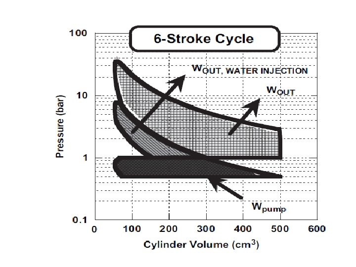
A Six Stroke Cycle with Water Injection

Schematic of typical intake & exhaust valve events for the six-stroke engine cycle.


Actual Scope for Expansion Process

Pressure Profile During Partial Compression of Exhaust

Work Consumed by Exhaust Compression Process

Instantaneous Water Injection
- Slides: 25