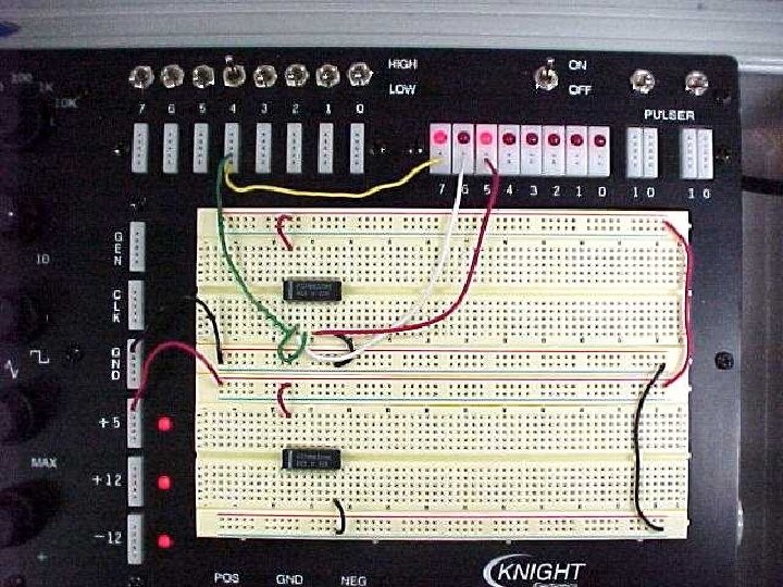
Wiring the Breadboard the right way Connecting the
")
Wiring the Breadboard (the right way)

Connecting the Power Supply • Connect the GND power supply to the blue BUS • Connect the +5 power supply to the red BUS

Expand the BUS to multiple breadboards • If using the top breadboard and the bottom breadboard JUMPER the two together at the far end of the breadboard BUS

Connecting GND to the chip • From the blue BUS (the GND of the power supply) JUMPER with a small piece of wire to the FIRST hole as shown (the black wire) • Always use the hole further from the chip

Connect +5 volts to the chip • From the red BUS (the +5 power supply) JUMPER with a small piece of wire to the FIRST hole as shown (the small red wire) • Always use the hole further from the chip

Connecting more chips to the power supply buses • Follow the same procedure to connect other chips to the power supply. • NEVER run power connections for each chip directly back to the power supply terminals

Signal wires to/from the chip • Always route the wires AROUND the chip. Never OVER the chip. • The “air space” above the chip must remain clear.

A properly wired circuit • Wires should be easy to trace. • The circuit wiring should be neat. • All wires should be cut just long enough to reach and striped correctly • Always wire with power off
- Slides: 10