
WIRELESS POWER TRANSFER Team SARAH MUSBAH AMAL ALOSH
WIRELESS POWER TRANSFER Team: SARAH MUSBAH AMAL ALOSH
Objective Client needs to charge a device that is not directly connected to a source, i. e. No Wires! Sub-Project for Saleh Alamassy Construct a testing device for a wireless charging system. Device will be used system set-up and deployment. 2
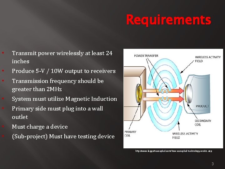
Requirements • Transmit power wirelessly at least 24 inches • Produce 5 -V / 10 W output to receivers • Transmission frequency should be greater than 2 MHz • System must utilize Magnetic Induction • Primary side must plug into a wall outlet • Must charge a device • (Sub-project) Must have testing device http: //www. leggettecoupled. com/how-ecoupled-technology-works. asp 3
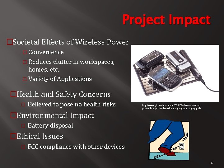
Project Impact �Societal Effects of Wireless Power � Convenience � Reduces clutter in workspaces, homes, etc. � Variety of Applications �Health and Safety Concerns � Believed to pose no health risks http: //www. gizmodo. com. au/2009/08/duracells-smartpower-lineup-includes-wireless-gadget-charging-pad/ �Environmental Impact � Battery disposal �Ethical Issues � FCC compliance with other devices 4
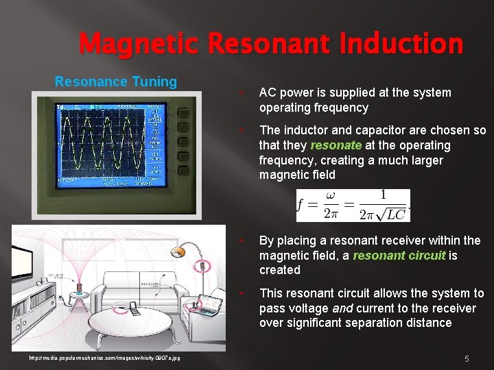
Magnetic Resonant Induction Resonance Tuning http: //media. popularmechanics. com/images/witricity-0907 a. jpg • AC power is supplied at the system operating frequency • The inductor and capacitor are chosen so that they resonate at the operating frequency, creating a much larger magnetic field • By placing a resonant receiver within the magnetic field, a resonant circuit is created • This resonant circuit allows the system to pass voltage and current to the receiver over significant separation distance 5
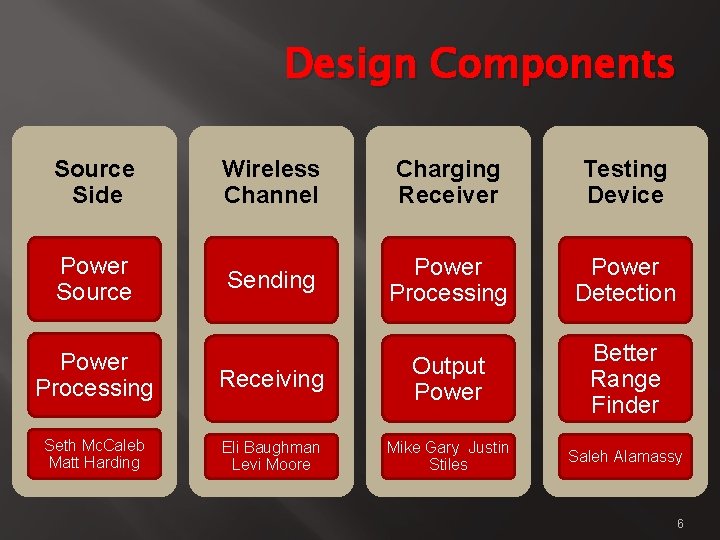
Design Components Source Side Wireless Channel Charging Receiver Testing Device Sending Power Processing Power Detection Power Processing Receiving Output Power Better Range Finder Seth Mc. Caleb Matt Harding Eli Baughman Levi Moore Mike Gary Justin Stiles Saleh Alamassy Power Source 6
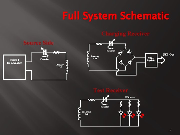
Full System Schematic Charging Receiver Source Side Tuning Capacitor Viking I RF Amplifier USB Out Receiving Coil Tuning Capacitor Voltage Regulator Primary Coil Test Receiver LED Array Tuning Capacitor Receiving Coil 7
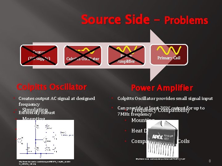
Source Side – Problems Source (DC supply) Colpitts Oscillator • Creates output AC signal at designed frequency Simulation • • Extremely robust • Mounting Power Amplifier Primary Coil Power Amplifier • Colpitts Oscillator provides small signal input • Can • provide at least. Compatibility 30 W output for up to Frequency 7 MHz frequency • Mounting • Heat Dissipation • Signal Quality • Compatibility With Coils http: //www. cirrus. com/en/pubs/pro. Datasheet/PA 107 U_A. pdf http: //www. biocrawler. com/w/images/f/f 6/NPN_Colpitts_oscillat or_collector_coil. png 8
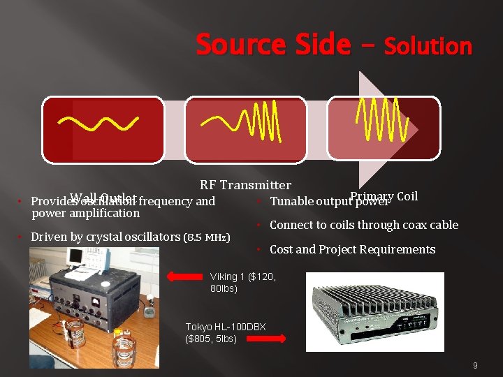
Source Side – Solution RF Transmitter Wall Outlet frequency and • Provides oscillation power amplification • Driven by crystal oscillators (8. 5 MHz) • Tunable output. Primary power Coil • Connect to coils through coax cable • Cost and Project Requirements Viking 1 ($120, 80 lbs) Tokyo HL-100 DBX ($805, 5 lbs) 9
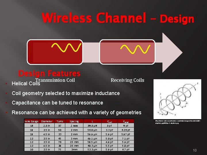
Wireless Channel – Design Features Receiving Coils Transmission Coil • Helical Coils • Coil geometry selected to maximize inductance • Capacitance can be tuned to resonance • Resonance can be achieved with a variety of geometries Wire Gauge Diameter 18 2. 5 in 18 4. 5 in 12 2. 5 in 12 4. 5 in 10 2. 5 in Turns 37 50 23 65 70 28 75 Spacing 2 mm 3 mm 2. 5 mm 3 mm L 39. 3 μH 56. 0 μH 59. 9 μH 49. 1 μH 58. 5 μH 60. 3 μH 52. 2 μH Ccoil 3 p. F 3. 3 p. F 5. 9 p. F 5. 0 p. F 4. 9 p. F 5. 5 p. F 5. 9 p. F Ctotal 9 p. F 6. 26 p. F 5. 97 p. F 7. 1 p. F 5. 9 p. F 5. 8 p. F 6. 7 p. F http: //www. advancedtubular. com/wiki/images/thumb/a/a 8/C oilpitch. jpg/400 px-Coilpitch. jpg 10
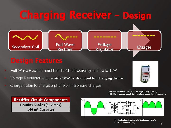
Charging Receiver – Design Secondary Coil Full-Wave Rectifier Voltage Regulator Charger Design Features • Full-Wave Rectifier must handle MHz frequency and up to 15 W • Voltage Regulator will provide 10 W 5 V dc output for charging device • Charger, plan to charge a phone with a phone charger. http: //www. robotshop. us/dimension-engineering-de-swadj 1. html? utm_source=google&utm_medium=base&utm_campaign=jos Rectifier Circuit Components Rectifier Diodes (50 V max) 100 m. F Capacitor http: //upload. wikimedia. org/wikipedia/commons/c /cc/Gratz. rectifier. en. png 11
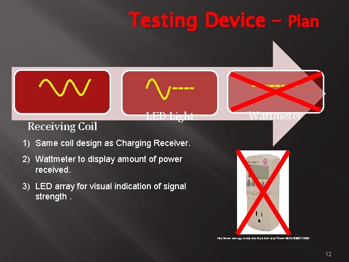
Testing Device – Plan Receiving Coil LED Light Wattmeter 1) Same coil design as Charging Receiver. 2) Wattmeter to display amount of power received. 3) LED array for visual indication of signal strength. http: //www. newegg. com/product. aspx? Item=N 82 E 16882715001 12
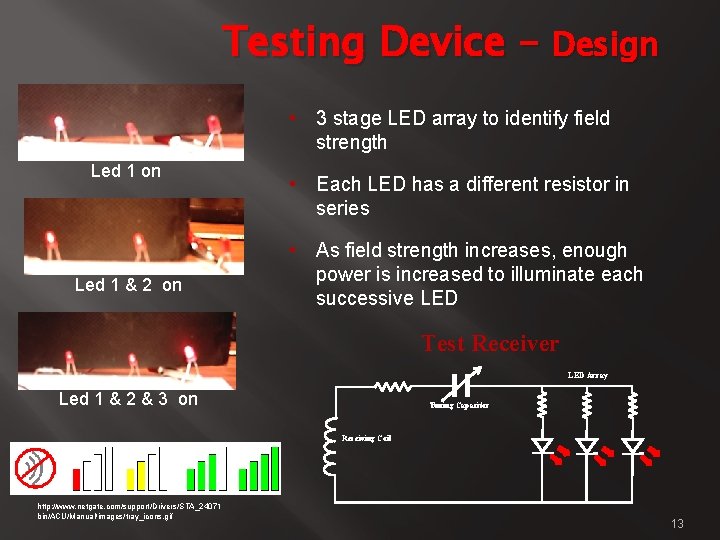
Testing Device – Design • 3 stage LED array to identify field strength Led 1 on Led 1 & 2 on • Each LED has a different resistor in series • As field strength increases, enough power is increased to illuminate each successive LED Test Receiver LED Array Led 1 & 2 & 3 on Tuning Capacitor Receiving Coil http: //www. netgate. com/support/Drivers/STA_24071 bin/ACU/Manual/images/tray_icons. gif 13
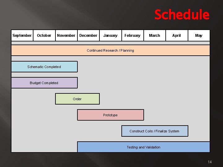
Schedule September October November December January February March April May Continued Research / Planning Schematic Completed Budget Completed Order Prototype Construct Coils / Finalize System Testing and Validation 14
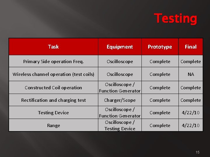
Testing Task Equipment Prototype Final Primary Side operation Freq. Oscilloscope Complete Wireless channel operation (test coils) Oscilloscope Complete NA Constructed Coil operation Oscilloscope / Function Generator Complete Rectification and charging test Charger/Scope Complete 4/22/10 Testing Device Range Oscilloscope / Function Generator Oscilloscope / Testing Device 15
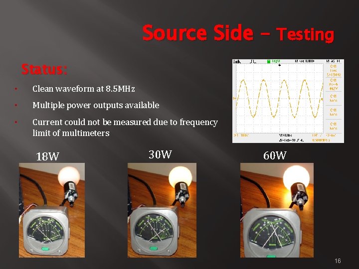
Source Side – Testing Status: • Clean waveform at 8. 5 MHz • Multiple power outputs available • Current could not be measured due to frequency limit of multimeters 18 W 30 W 60 W 16
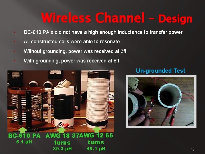
Wireless Channel – Design • BC-610 PA’s did not have a high enough inductance to transfer power • All constructed coils were able to resonate • Without grounding, power was received at 3 ft • With grounding, power was received at 8 ft Un-grounded Test BC-610 PA AWG 18 37 AWG 12 65 5. 1 µH turns 39. 3 µH 49. 1 µH 17
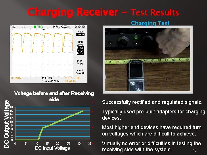
Charging Receiver – Test Results Charging Test DC Output Voltage Oscilloscope Waveform Voltage before and after Receiving side • 18 16 14 12 10 8 6 4 2 0 0 5 10 15 20 25 DC Input Voltage 30 35 Successfully rectified and regulated signals. • Typically used pre-built adapters for charging devices. • Most higher end devices have required turn on voltages which are difficult to achieve. • Virtually no error or difficulties in testing the receiving side with the system. 18
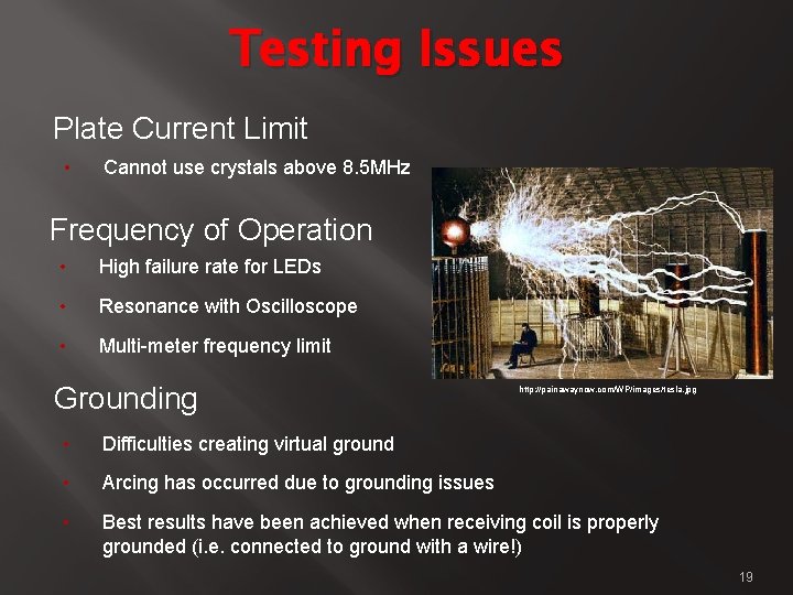
Testing Issues Plate Current Limit • Cannot use crystals above 8. 5 MHz Frequency of Operation • High failure rate for LEDs • Resonance with Oscilloscope • Multi-meter frequency limit Grounding http: //painawaynow. com/WP/images/tesla. jpg • Difficulties creating virtual ground • Arcing has occurred due to grounding issues • Best results have been achieved when receiving coil is properly grounded (i. e. connected to ground with a wire!) 19
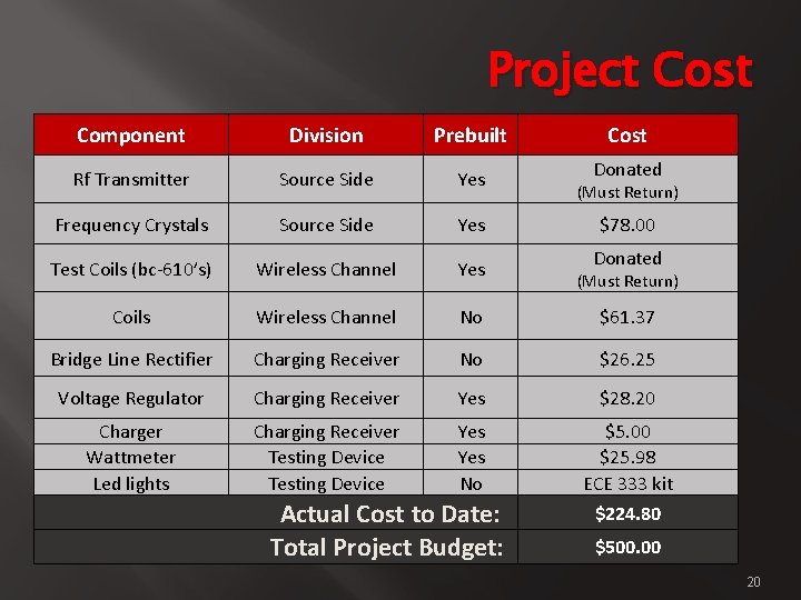
Project Cost Component Division Prebuilt Rf Transmitter Source Side Yes Frequency Crystals Source Side Yes Test Coils (bc-610’s) Wireless Channel Yes Coils Wireless Channel No $61. 37 Bridge Line Rectifier Charging Receiver No $26. 25 Voltage Regulator Charging Receiver Yes $28. 20 Charger Wattmeter Led lights Charging Receiver Testing Device Yes No $5. 00 $25. 98 ECE 333 kit $224. 80 Actual Cost to Date: Total Project Budget: Cost Donated (Must Return) $78. 00 Donated (Must Return) $500. 00 20
Questions? http: //neatorama. cachefly. net/images/2009 -04/tesla-rodin-thinker. jpg 21
- Slides: 21