
Wireless Networks Lecture 11 Fundamentals of Cellular Networks


- Slides: 22
Wireless Networks Ü Lecture 11 Ü Fundamentals of Cellular Networks (Part I) Ü Dr. Ghalib A. Shah 1
Outlines Ü Ü Ü Review of last lecture Cellular Concept Frequency Reuse Locating co-channel cells Example Summary of today’s lecture 2
Review of last lecture Ü Limitation of 3 G Ü 4 G ► ► ► Objectives Issues Qo. S Security Multimedia Service Applications Ü Convergence of Cellular and WLAN Ü Billing Issue Ü Wireless Networks 3
Introduction Ü Early mobile system objective was to achieve a large coverage usingle high power antenna Ü Impossible to reuse the same frequencies in the same coverage area. Ü For example, Bell mobile system in 1970 could support maximum of 12 simultaneous calls over a thousand square mile. Ü The Govt regulatory could not make spectrum allocation proportion to the increasing demand Ü Became imperative to restructure the telephone system to achieve high capacity with limited radio spectrum. 4
Cellular Concept Ü Cellular concept was a major breakthrough in solving problem of spectrum congestion and user capacity Ü Offers high capacity without any major change in technology ► Replacing high-power transmitter (large cell) with many lowpower transmitter (small cells) each providing service to small ► Each BS is allocated a portion of the channels. ► Nearby BS are assigned different group of channels ► So that all the available channels are distributed among the nearby BS. ► May be reused as many times as necessary as long as the BS using same channels are not in overlapping. 5
Ü As the demand for service increases, the number of BS can be increased with reduced transmission power. Ü Thereby providing additional capacity with no addition to spectrum. Ü This is the foundation of for all modern wireless communication systems. 6
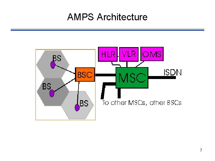
AMPS Architecture 7
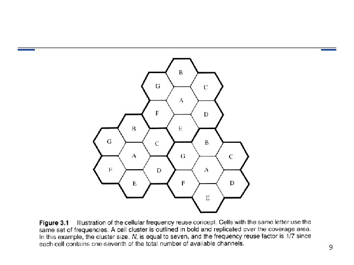
Frequency Reuse Ü Relies on intelligent allocation and reuse of channels. Ü A small geographical area with allocation of a group of channels is called cell. Ü BS antennas are designed to achieve the desired coverage within a cell avoiding cochannel interference. Ü The design process of selecting and allocating channel groups for all the cellular BS is called frequency reuse or frequency planning. 8
9
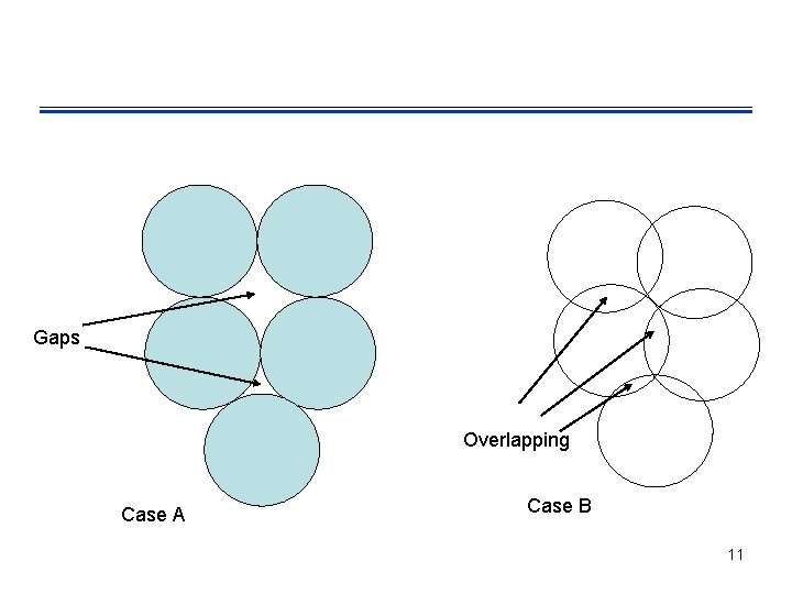
Ü The hexagonal shape representing a cell is conceptual and simplistic model of coverage. Ü The actual radio coverage is known as the footprint and is determined from field measurement, propagation prediction models ► However a regular shape is needed for systematic system design and adaptation to future growth. Ü It might be natural to choose a circle to represent coverage but adjacent circles cannot be overlaid upon a map without leaving gaps or creating overlapping. 10
Gaps Overlapping Case A Case B 11
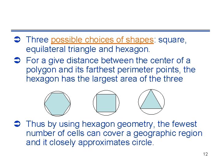
Ü Three possible choices of shapes: square, equilateral triangle and hexagon. Ü For a give distance between the center of a polygon and its farthest perimeter points, the hexagon has the largest area of the three Ü Thus by using hexagon geometry, the fewest number of cells can cover a geographic region and it closely approximates circle. 12
Capacity of System Ü When using hexagon to model coverage areas ► Center-excited Cell: BS depicted as being either in the center of the cell • Omni-directional antenna is used ► Edge-excited Cell: on three of the six cell vertices • Sectored direction antenna is used Ü Consider a cellular system ► which has S duplex channels available for reuse. ► Each cell allocated group of k channels (k < S) ► S channels divided among N cells (unique and disjoint) then S = k. N 13
Ü Cluster: N cells, which collectively use the complete set of available frequencies Ü If a cluster is replicated M times in the system, the number of duplex channels C as a measure of capacity is C = Mk. N = MS Ü So capacity is directly proportional to the replication factor in a fixed area. Ü Factor N is called cluster size and is typically equal to 4, 7, 12. 14
Ü If cluster size N is reduced while cell size is kept constant ► more clusters are required ► More capacity is achieved Ü Large cluster size indicates that co-channel cells are far from each other Ü Conversely, small cluster size means cochannel cells are located much closer together Ü The value of N is a function of how much interference a mobile or BS can tolerate 15
Ü Clusters are inversely proportion to N ► Capacity is directly proportional to Clusters ► Thus frequency reuse factor is given by 1/N. Ü In last fig, each hexagon has exactly six equidistant neighbors and that the lines joining the centers of any cell and its neighbors are separated by multiple of 60 degrees. ► There are only certain cluster sizes and layouts possible 16
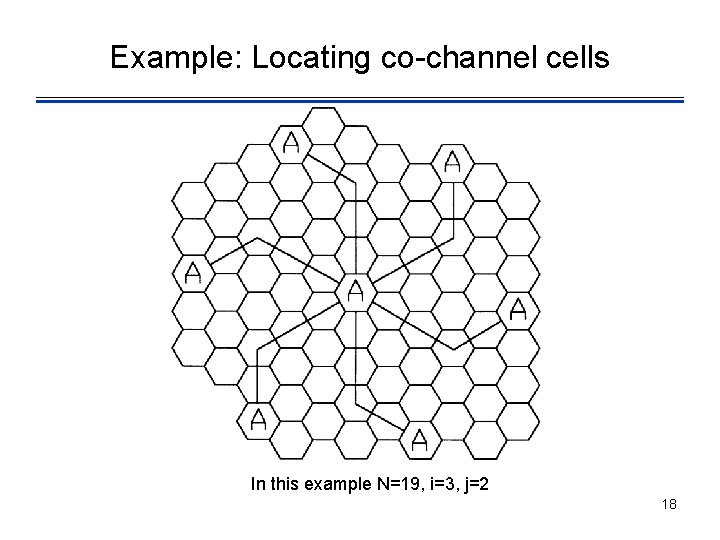
Locating co-channel neighbors Ü To connect hexagons without gaps, ► The geometry of hexagon is such that the number of cells per cluster N can only have values N = i 2 + ij + j 2 where i and j are non-negative integers. Ü To find out the nearest co-channel neighbors of a particular cell, do the following ► Move I cells along any chain of hexagon ► Then turn 60 degree counter clockwise and move j cells 17
Example: Locating co-channel cells In this example N=19, i=3, j=2 18
Example Ü BW = 33 MHz allocated to particular FDD cellular system, where two 25 KHz simplex channel to provide full-duplex for voice/data. Ü Compute the number of channels per cell if a system uses ► Four-cell reuse ► Seven-cell reuse ► Twelve-cell reuse. Ü If 1 MHz is dedicated to control channels, determine equitable distribution of control and voice channels per cell for above three systems? 19
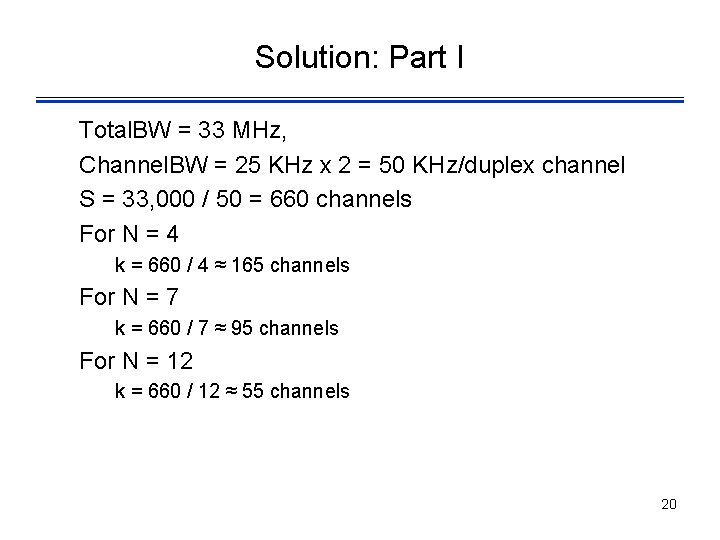
Solution: Part I Total. BW = 33 MHz, Channel. BW = 25 KHz x 2 = 50 KHz/duplex channel S = 33, 000 / 50 = 660 channels For N = 4 k = 660 / 4 ≈ 165 channels For N = 7 k = 660 / 7 ≈ 95 channels For N = 12 k = 660 / 12 ≈ 55 channels 20
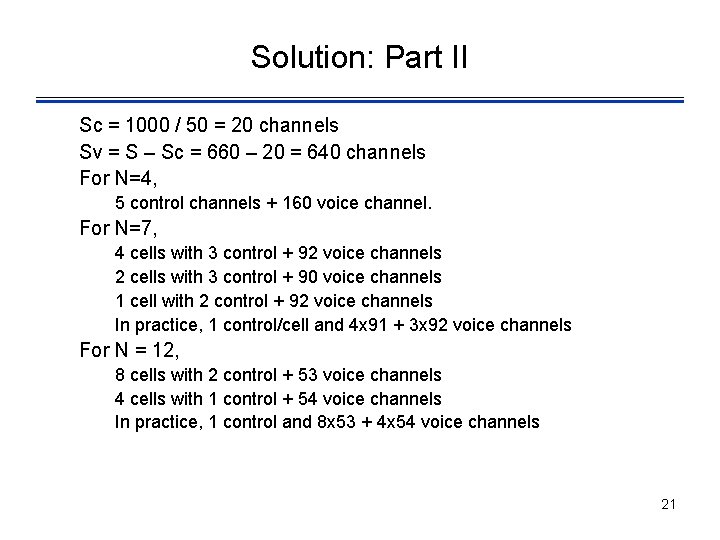
Solution: Part II Sc = 1000 / 50 = 20 channels Sv = S – Sc = 660 – 20 = 640 channels For N=4, 5 control channels + 160 voice channel. For N=7, 4 cells with 3 control + 92 voice channels 2 cells with 3 control + 90 voice channels 1 cell with 2 control + 92 voice channels In practice, 1 control/cell and 4 x 91 + 3 x 92 voice channels For N = 12, 8 cells with 2 control + 53 voice channels 4 cells with 1 control + 54 voice channels In practice, 1 control and 8 x 53 + 4 x 54 voice channels 21
Summary Ü Ü Ü Cellular Concept Frequency Reuse Locating co-channel cells Example Next Lecture ► Handoff Strategies ► Interference and System Capacity 22