Wireless Communication Devices SPP Serial Port Protocol Bluetooth

Wireless Communication Devices
 Bluetooth Module • • • Pins: These small size Bluetooth")
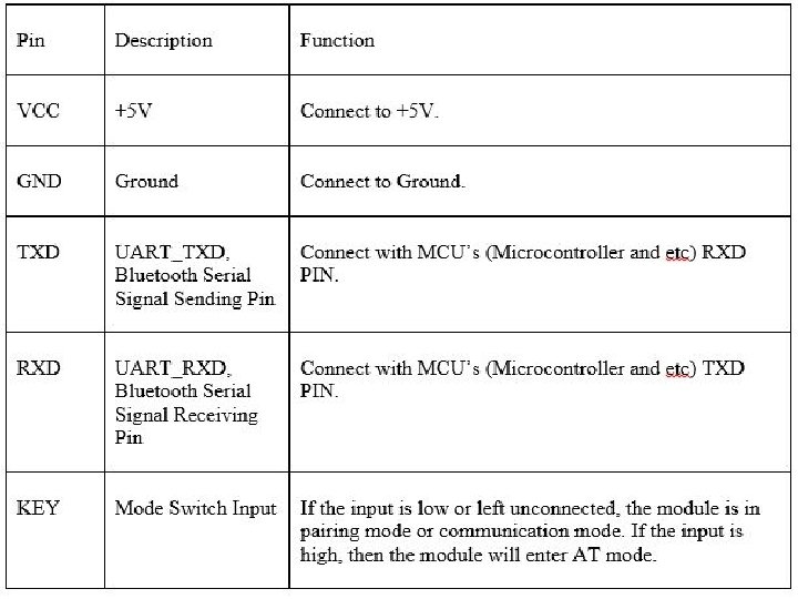
SPP (Serial Port Protocol) Bluetooth Module • • • Pins: These small size Bluetooth TTL transceiver modules are designed for serial communication. It allows your target device to both send or receive TTL data via Bluetooth technology without connecting a serial cable to your computer. The modules with the HC-03 and HC-05 firmware the Master and Slave integrated Bluetooth serial modules with firmware which allows you to modify master and slave mode at any time. HC 03 are industrial grade products, HC-05 are commercial grade products. The modules with the HC-04 and HC-06 firmware the modules which are factory set to be Master or Slave modules. Master and slave mode cannot be switched from the factory setting. HC 04 is an industrial grade product, HC-06 is a commercial grade product. The modules with the HC-09 firmware replacements for the HC-06 and HC-07 modules. HC-05 module is an easy to use Bluetooth SPP module, designed for transparent wireless serial connection setup. Serial port Bluetooth module is fully qualified Bluetooth V 2. 0+EDR (Enhanced Data Rate) 3 Mbps Modulation with complete 2. 4 GHz radio transceiver and baseband. - Master/Slave - Configuration using AT commands VCC (Power 3. 3 – 6 V) GND TXD RXD

Hardware Features • • • Bluetooth protocol: Bluetooth Specification v 2. 0+EDR Frequency: 2. 4 GHz ISM band Modulation: GFSK(Gaussian Frequency Shift Keying) Speed: Asynchronous: 2. 1 Mbps(Max) / 160 kbps, Synchronous: 1 Mbps/1 Mbps Security: Authentication and encryption Profiles: Bluetooth serial port Power supply: +3. 3 VDC 50 m. A Typical -80 d. Bm sensitivity Up to +4 d. Bm RF transmit power Low Power 1. 8 V Operation , 1. 8 to 3. 6 V I/O UART interface with programmable baud rate With integrated antenna

Bluetooth Module • WAKEUP/EN/KEY PIN: Enter into AT Mode when HIGH • STATE PIN: The STATE pin is LOW when the HC-05 is not connected and HIGH when the HC-05 is connected (Connected to LED). • • HC-05 blinks constant ready light when on and searching for device to connect to HC-05 indicates connected when blinking light is stalled and not constant

AT Command Purpose Command Verify Connection AT Set Name AT+Name = <name> Set Role AT+Role = 1(Master)/0(Slave) Set Pairing Code AT+PSWD = <password> Pairing Options AT+CMODE = 1(Auto)/0(Last Address)

ESP 8266 -1
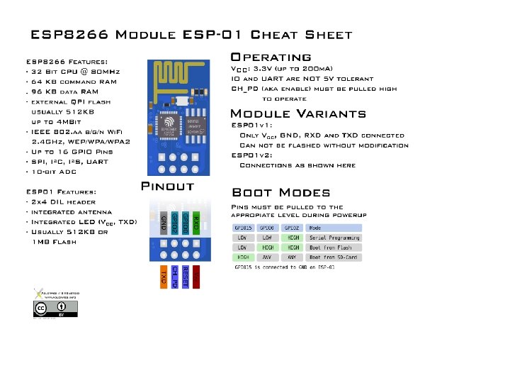

ESP 8266 Features • • • • The ESP 8266 is a low-cost Wi-Fi chip with full TCP/IP stack and MCU (Micro Controller Unit) capability 32 -bit RISC CPU: Tensilica Xtensa LX 106 running at 80 MHz* 64 KB of instruction RAM, 96 KB of data RAM External QSPI flash - 512 KB to 4 MB* (up to 16 MB is supported) IEEE 802. 11 b/g/n Wi-Fi Integrated TR switch, balun, LNA, power amplifier and matching network WEP or WPA/WPA 2 authentication, or open networks 16 GPIO pins SPI, I²C, I²S interfaces with DMA (sharing pins with GPIO) UART on dedicated pins, plus a transmit-only UART can be enabled on GPIO 2 1 10 -bit ADC * Both the CPU and flash clock speeds can be doubled by overclocking on some devices. CPU can be run at 160 MHz and flash can be sped up from 40 MHz to 80 MHz. Success varies chip to chip.

Zigbee

• Zig. Bee RF modules provide cost effective wireless connectivity to electronic devices. • XCTU is a free, multi-platform application compatible with Windows, Mac. OS and Linux • Graphical Network View for simple wireless network configuration and architecture • API Frame Builder is a simple development tool for quickly building XBee API frames • XCTU: • https: //www. digi. com/products/xbee-rf-solutions/xctusoftware/xctu#productsupport-utilities • Examles: http: //www. digi. com/blog/category/examplesguides/


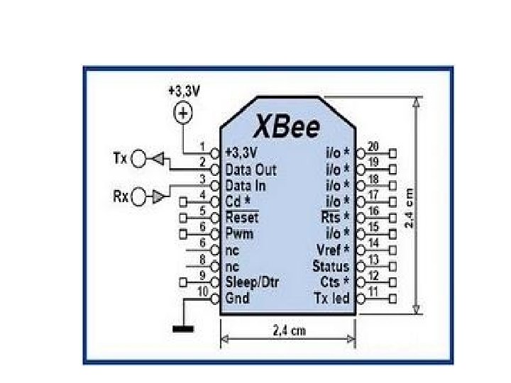
Features: • • • 3. 3 V @ 40 m. A 250 kbps Max data rate 2 m. W output (+3 d. Bm) 400 ft (120 m) range Built-in antenna Fully FCC certified 6 10 -bit ADC input pins 8 digital IO pins 128 -bit encryption Local or over-air configuration AT or API command set

GSM+GPS

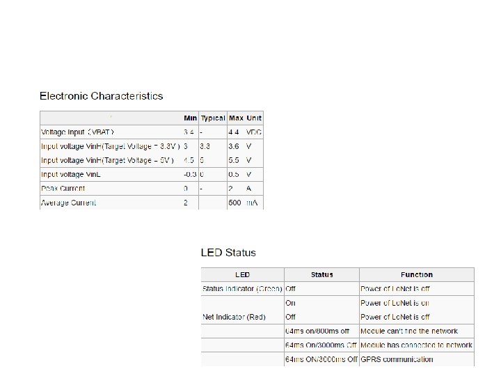
Features • Quad-band 850/900/1800/1900 MHz • GPRS multi-slot class 12 connectivity: max. 85. 6 kbps(download/up-load) • GPRS mobile station class B • Controlled by AT Command (3 GPP TS 27. 007, 27. 005 and SIMCOM enhanced AT Commands) • Supports charging control for Li-Ion battery • Supports Real Time Clock • Supply voltage range 3. 4 V ~ 4. 4 V • Integrated GPS/CNSS and supports A-GPS • Supports 3. 0 V to 5. 0 V logic level • Low power consumption, 1 m. A in sleep mode • Supports GPS NMEA protocol • Standard SIM Card
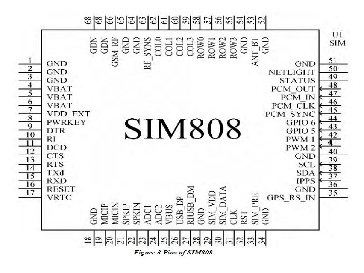

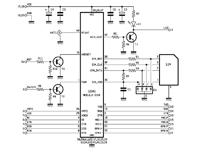
Pin Map • • PWR: this is soft power switch for the module, you can pull it to high level for at least 2 s to power up or power down the module. RI: this pin will tell you whether the module is on and is there any calls and messages received. It will be pulled to high level when the module is on. And it will change to low for 120 ms when a call or message is received. RST: this is reset pin for the module. By default it has a high pull-up. If you absolutely got the module in a bad space, you can pull it to low level for 100 ms to perform a hard reset. RXD / TXD: Serial port, the module uses it to send and receive commands and data. TXD is output, and RXD is input. They can be connected to the 3. 3 V and 5 V level. VIO: this is the reference logic level for serial port of the module, the input voltage depends on the logical level of the microcontroller you use. If you use a 5 V microcontroller like Arduino, you should have it be 5 V, and a 3 V logic microcontroller you should set it to 3 V. BAT: this pin is connected to Li-Ion battery pin, if you want to use only one Li-Ion battery as your power supply, you can use it to drive you microcontroller. DTR: this is wake up pin for module in sleep mode. By default it has a high pull-up, and you can set the module into sleep mode by AT command “AT+CSCLK=1”. In the meantime, the serial port will be disabled. The serial port will be active after DTR pin is pulled to low level for about 50 ms.
 Humidity sensor (Serial) Optical Motion (Digital) Magnetic (Digital) Distance")
SENSORS • Sensor Temperature (analog) Humidity sensor (Serial) Optical Motion (Digital) Magnetic (Digital) Distance (Analog Non linear) Audio I/P & O/P (Analog) Light (Analog) • Computational Unit ARM-Cortex STM 32 F 051 R 8 • Communication GSM+GPS Bluetooth Zigbee Wi-Fi

WSN Computational Requirements STM 32 F 051 R 8 It has the following key features: Core and operating conditions – ARM® Cortex. TM-M 0 0. 9 DMIPS/MHz up to 48 MHz – 1. 8/2. 0 to 3. 6 V supply range High-performance connectivity - 6 Mbit/s USART – 18 Mbit/s SPI with 4 - to 16 -bit data frame – 1 Mbit/s I 2 C fast-mode plus – HDMI CEC Enhanced control – 1 x 16 -bit 3 -phase PWM motor control timer – 5 x 16 -bit PWM timers – 1 x 16 -bit basic timer – 1 x 32 -bit PWM timer – 12 MHz I/O toggling Memory: 64 KB Flash 8 KB RAM PC 8= Blue LED PC 9= Green LED

Specifications from data sheet System Architecture: Page – 43 Memory organization: Page - 45 CRC: Page-79 Power Supply: Page -85 Lopower Modes: Page-89 Clock Sources: Page-101, 103 PLL: Page-118 GPIO-Page-156 System Configuration: Page-173
- Slides: 27