
Wind loading and structural response Lecture 23 Dr

- Slides: 24
Wind loading and structural response Lecture 23 Dr. J. D. Holmes Antennas and open-frame structures
Antennas and open-frame structures • Antennas - isolated structures - radio telescopes and microwave antennas • Antennas - attached to towers - aerodynamic interference • Single frames • Multiple frames • Lattice towers Common feature : aerodynamic interference between various elements - e. g. antennas and supporting tower or other antennas, members of a frame
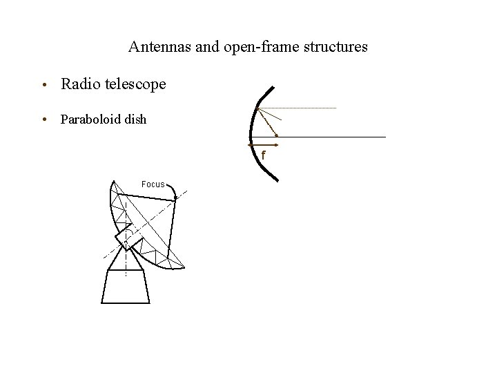
Antennas and open-frame structures • Radio telescope • Paraboloid dish f Focus
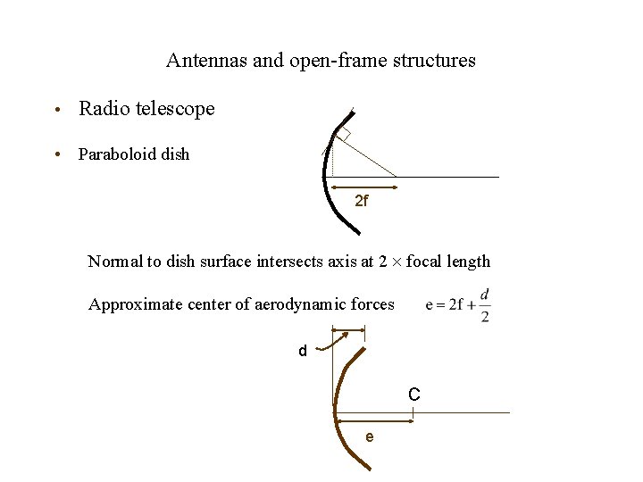
Antennas and open-frame structures • Radio telescope • Paraboloid dish 2 f Normal to dish surface intersects axis at 2 focal length Approximate center of aerodynamic forces d C e
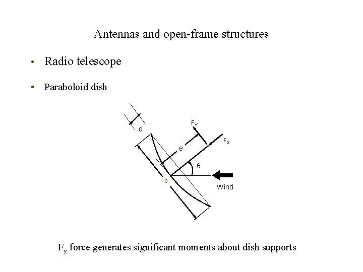
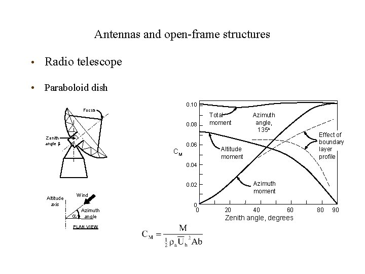
Antennas and open-frame structures • Radio telescope • Paraboloid dish FY d FX e b Wind Fy force generates significant moments about dish supports
Antennas and open-frame structures • Radio telescope • Paraboloid dish 0. 10 Focus 0. 08 Zenith angle b CM 0. 06 Total moment Azimuth angle, 135 o Effect of boundary layer profile Altitude moment 0. 04 Azimuth moment 0. 02 Wind Altitude axis Azimuth angle PLAN VIEW 0 0 20 40 60 Zenith angle, degrees 80 90
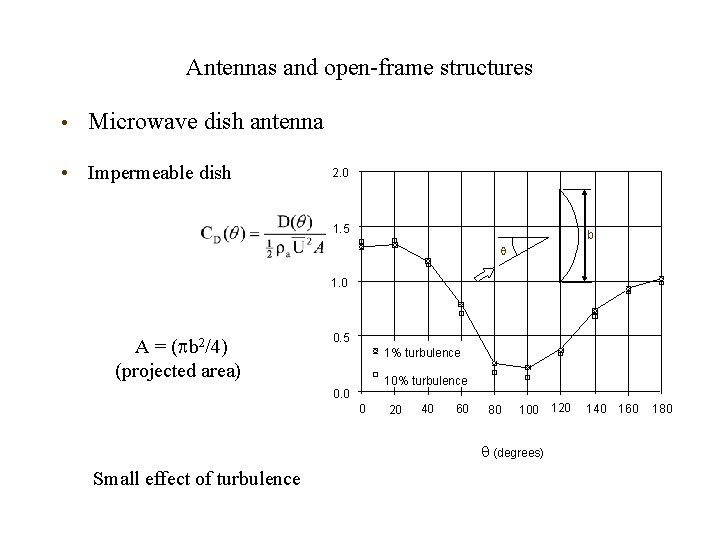
Antennas and open-frame structures • Microwave dish antenna • Impermeable dish 2. 0 1. 5 b 1. 0 A = ( b 2/4) (projected area) 0. 5 1% turbulence 10% turbulence 0. 0 0 20 40 60 80 100 120 (degrees) Small effect of turbulence 140 160 180
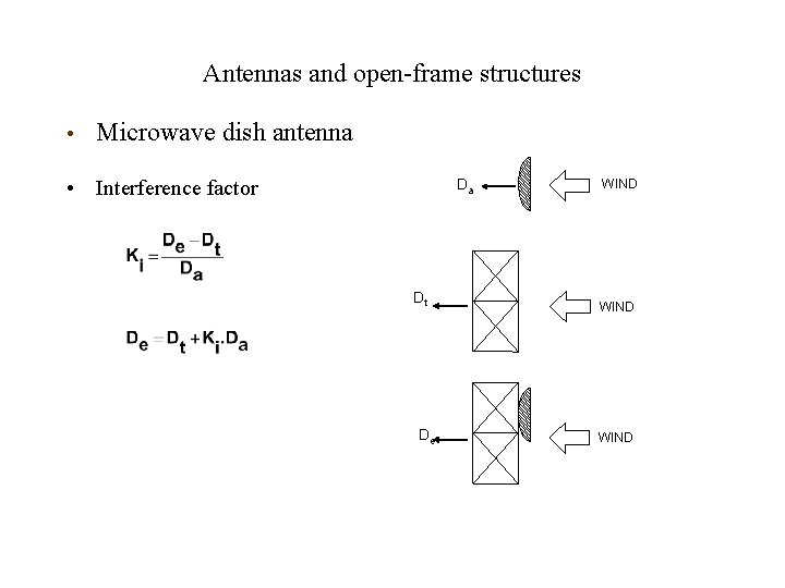
Antennas and open-frame structures • Microwave dish antenna • Interference factor Da Dt De WIND
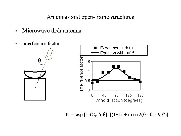
Antennas and open-frame structures • Microwave dish antenna • Interference factor Experimental data Equation with t=0. 5 1 0. 5 0 0 45 90 135 180 Wind direction (degrees) Ki = exp [-k(CD )2]. [(1+t) + t cos 2( - d - 90 )]
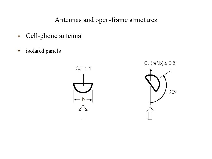
Antennas and open-frame structures • Cell-phone antenna • isolated panels Cd 1. 1 Cd (ref. b) 0. 8 120 O b
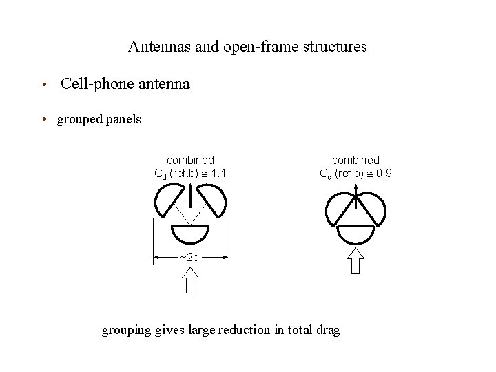
Antennas and open-frame structures • Cell-phone antenna • grouped panels combined Cd (ref. b) 1. 1 combined Cd (ref. b) 0. 9 ~2 b grouping gives large reduction in total drag
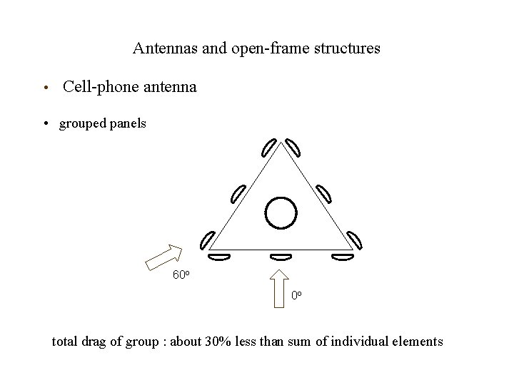
Antennas and open-frame structures • Cell-phone antenna • grouped panels 60 o 0 o total drag of group : about 30% less than sum of individual elements
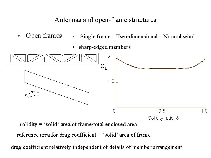
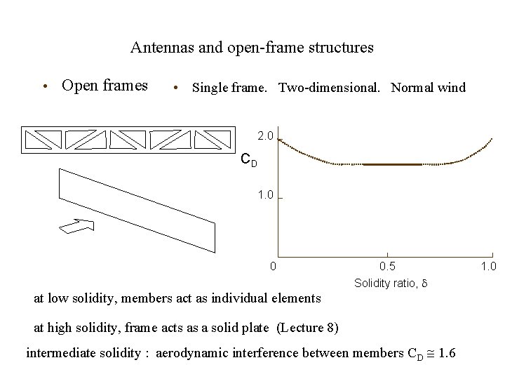
Antennas and open-frame structures • Open frames • Single frame. Two-dimensional. Normal wind • sharp-edged members 2. 0 CD 1. 0 0 0. 5 Solidity ratio, solidity = ‘solid’ area of frame/total enclosed area reference area for drag coefficient = ‘solid’ area of frame drag coefficient relatively independent of details of member arrangement 1. 0
Antennas and open-frame structures • Open frames • Single frame. Two-dimensional. Normal wind 2. 0 CD 1. 0 0 0. 5 Solidity ratio, at low solidity, members act as individual elements at high solidity, frame acts as a solid plate (Lecture 8) intermediate solidity : aerodynamic interference between members C D 1. 6 1. 0
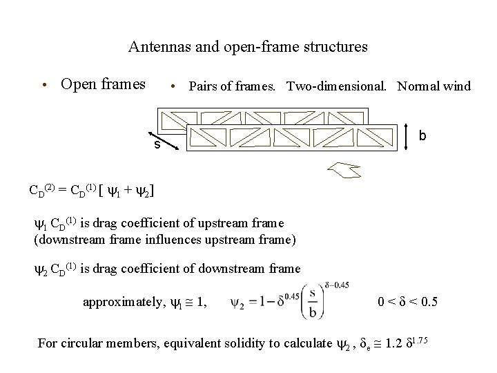
Antennas and open-frame structures • Open frames • Pairs of frames. Two-dimensional. Normal wind s b CD(2) = CD(1) [ 1 + 2] 1 CD(1) is drag coefficient of upstream frame (downstream frame influences upstream frame) 2 CD(1) is drag coefficient of downstream frame approximately, 1 1, 0 < < 0. 5 For circular members, equivalent solidity to calculate 2 , e 1. 2 1. 75
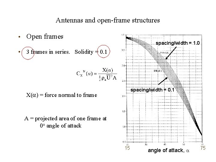
Antennas and open-frame structures • Open frames spacing/width = 1. 0 • 3 frames in series. Solidity = 0. 1 spacing/width = 0. 1 X( ) = force normal to frame A = projected area of one frame at 0 o angle of attack 15 angle of attack, 75
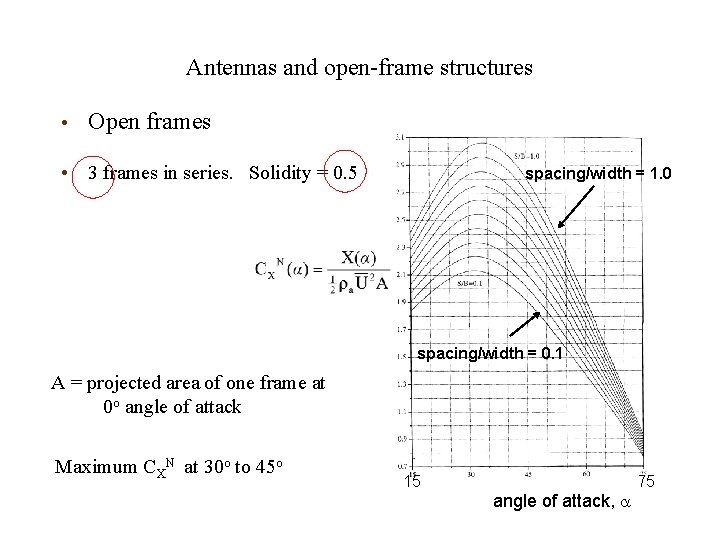
Antennas and open-frame structures • Open frames • 3 frames in series. Solidity = 0. 5 spacing/width = 1. 0 spacing/width = 0. 1 A = projected area of one frame at 0 o angle of attack Maximum CXN at 30 o to 45 o 15 angle of attack, 75
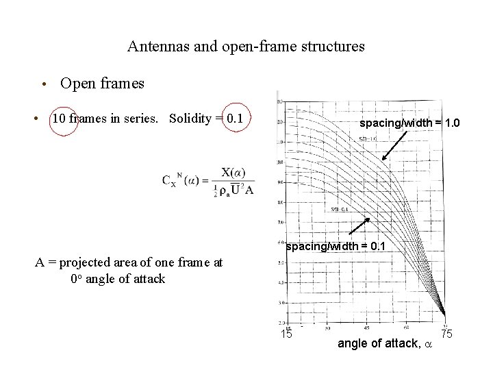
Antennas and open-frame structures • Open frames • 10 frames in series. Solidity = 0. 1 spacing/width = 1. 0 spacing/width = 0. 1 A = projected area of one frame at 0 o angle of attack 15 angle of attack, 75
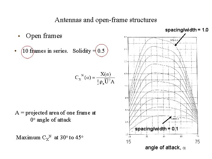
Antennas and open-frame structures spacing/width = 1. 0 • Open frames • 10 frames in series. Solidity = 0. 5 A = projected area of one frame at 0 o angle of attack spacing/width = 0. 1 Maximum CXN at 30 o to 45 o 15 angle of attack, 75
Antennas and open-frame structures • Open frames • Design method : ‘Wind loads and anchor bolt design for petrochemical facilities’ (ASCE) Needs more wind tunnel studies for pipe racks etc.
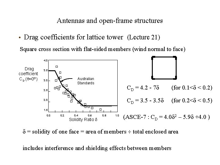
Antennas and open-frame structures • Drag coefficients for lattice tower (Lecture 21) Square cross section with flat-sided members (wind normal to face) 4. 0 Drag coefficient CD ( =0 O) 3. 5 Australian Standards 3. 0 2. 5 2. 0 CD = 4. 2 - 7 (for 0. 1< < 0. 2) CD = 3. 5 - 3. 5 (for 0. 2< < 0. 5) 1. 5 0. 0 0. 2 0. 4 0. 6 Solidity Ratio 0. 8 1. 0 (ASCE-7 : CD = 4. 0 2 – 5. 9 +4. 0 ) = solidity of one face = area of members total enclosed area includes interference and shielding effects between members
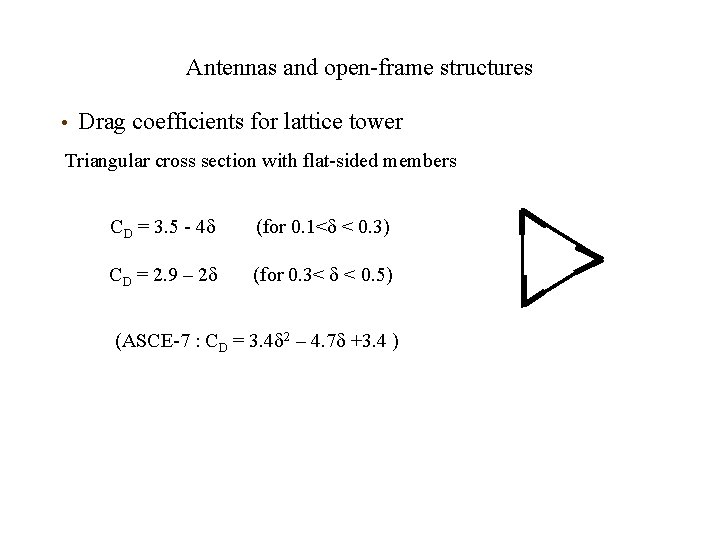
Antennas and open-frame structures • Drag coefficients for lattice tower Triangular cross section with flat-sided members CD = 3. 5 - 4 (for 0. 1< < 0. 3) CD = 2. 9 – 2 (for 0. 3< < 0. 5) (ASCE-7 : CD = 3. 4 2 – 4. 7 +3. 4 )
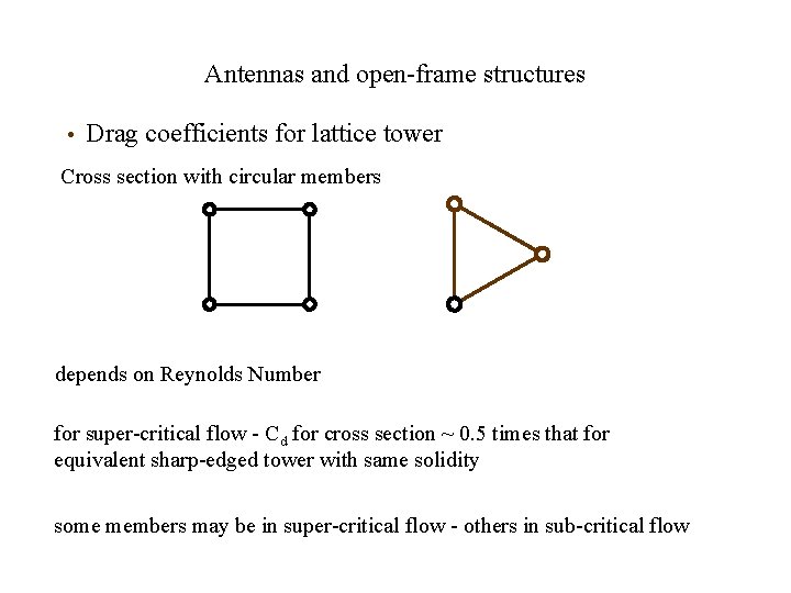
Antennas and open-frame structures • Drag coefficients for lattice tower Cross section with circular members depends on Reynolds Number for super-critical flow - Cd for cross section ~ 0. 5 times that for equivalent sharp-edged tower with same solidity some members may be in super-critical flow - others in sub-critical flow
End of Lecture 23 John Holmes 225 -405 -3789 JHolmes@lsu. edu