
Wind Compensation for Small Sounding Rockets Blowing winds
Wind Compensation for Small Sounding Rockets Blowing winds move all Rockets too, oft way off course Science fixes that Seventh IREC, June 2012 Green River, UT C. P. Hoult & Ashlee Espinoza CSULB Also Eighth IREC, June 2013 C. P. Hoult and Elvia Cortez CSULA
Topic Outline • Wind measurement • Launcher compensation • Summary
Wind Measurement

Wind Power Spectral Density • cyclonic weather turbulence diurnal breezes 100 hours 1 hour 0. 01 hour Isaac Van der Hoven, “Power Spectrum of Horizontal Wind Speed in the Frequency Range from 0. 0007 to 900 Cycles per Hour”, Journal of Meteorology, Vol 14 (1957), pp 160 -164
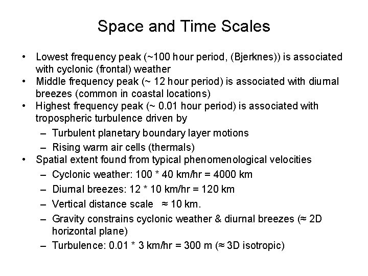
Space and Time Scales • Lowest frequency peak (~100 hour period, (Bjerknes)) is associated with cyclonic (frontal) weather • Middle frequency peak (~ 12 hour period) is associated with diurnal breezes (common in coastal locations) • Highest frequency peak (~ 0. 01 hour period) is associated with tropospheric turbulence driven by – Turbulent planetary boundary layer motions – Rising warm air cells (thermals) • Spatial extent found from typical phenomenological velocities – Cyclonic weather: 100 * 40 km/hr = 4000 km – Diurnal breezes: 12 * 10 km/hr = 120 km – Vertical distance scale ≈ 10 km. – Gravity constrains cyclonic weather & diurnal breezes (≈ 2 D horizontal plane) – Turbulence: 0. 01 * 3 km/hr = 300 m (≈ 3 D isotropic)
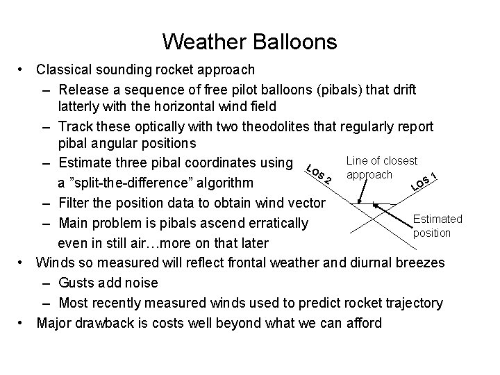
Weather Balloons • Classical sounding rocket approach – Release a sequence of free pilot balloons (pibals) that drift latterly with the horizontal wind field – Track these optically with two theodolites that regularly report pibal angular positions Line of closest – Estimate three pibal coordinates using LO S approach 1 2 S a ”split-the-difference” algorithm O L – Filter the position data to obtain wind vector Estimated – Main problem is pibals ascend erratically position even in still air…more on that later • Winds so measured will reflect frontal weather and diurnal breezes – Gusts add noise – Most recently measured winds used to predict rocket trajectory • Major drawback is costs well beyond what we can afford

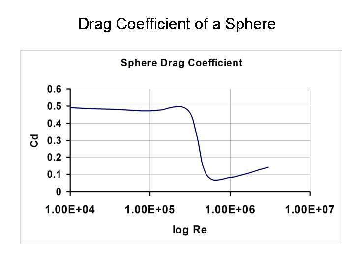
Tethered Pilot Balloon (Pibal) Wind Sensor Typical Data • Pibal* • Type: Natural rubber • Diameter: 118 cm (inflated) • Weight: 200 gm • Net lift: ~800 gm • Drag coefficient**: 0. 14 (Re = 106) • Tether*** • Material: braided Fins • Spectra 2000 ® • Diameter: 0. 033 cm • Tensile strength: 22. 7 kg • Weight: 0. 083 gm/m • Altitude: 40 m * Scientific Sales, Inc. web site ** S. F. Hoerner, “Fluid-Dynamic Drag”, 1965 *** Honeywell literature Wind Drag Pibal LOS Catenary Tether Elevation Angle Sensor Optics
Drag Coefficient of a Sphere
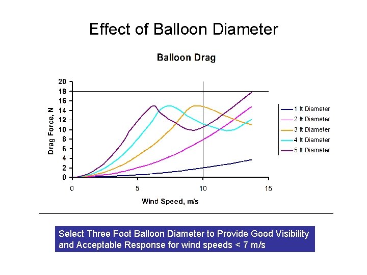
Effect of Balloon Diameter Select Three Foot Balloon Diameter to Provide Good Visibility and Acceptable Response for wind speeds < 7 m/s
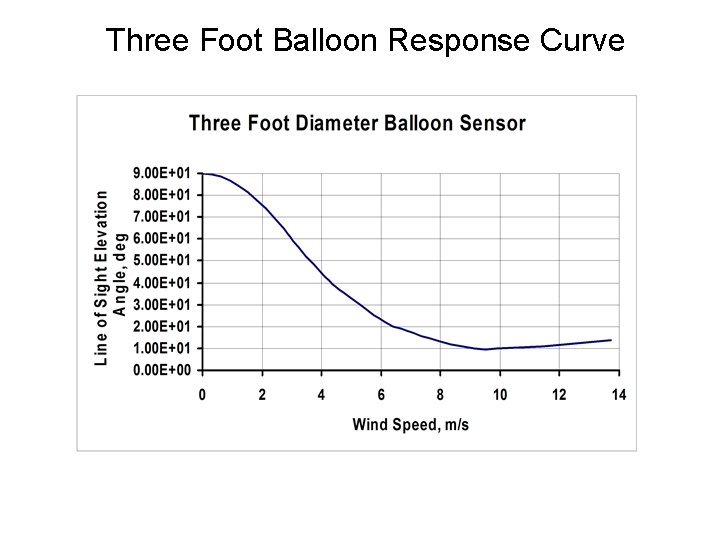
Three Foot Balloon Response Curve
Balloon • Inflation Techniques – Template to control diameter • Sources
Winch & Spectra™ • • • Spectra™ 2000, the wonder material Made of polyethylene How strong it is… 15 x steel at same weight Used for fishing line & bullet-proof vests How thin ours is: 0. 011” diameter! Bias errors from sag due to gravity and aerodynamic drag compensated in software • Winch design & operations
Sky. Scout™ • How it works – Accelerometers for elevation angle – Magnetometers for azimuth angle – GPS to locate Earth’s magnetic field – Computer • How to use it…settings & which windows have our angles • Telescope & Tripod – BTW, also good for star parties
Wind Measurement at Higher Altitudes • Tethered Pibal wind measurement works up to about 1 km altitude – But our rockets fly much higher than that. What’s to be done? • Answer: Don’t worry! – We can get the high altitude winds from the FAA via the Internet – Go to Winds and Temperatures Aloft – Air Sports Net • Select one of about 100 American cities near launch site • Select Forecast hours of applicability • Select Azimuth directions • Enter FAA and tethered pibal wind data into WIND CALCULATOR. xlsx • Product is N-S and E-W wind profiles
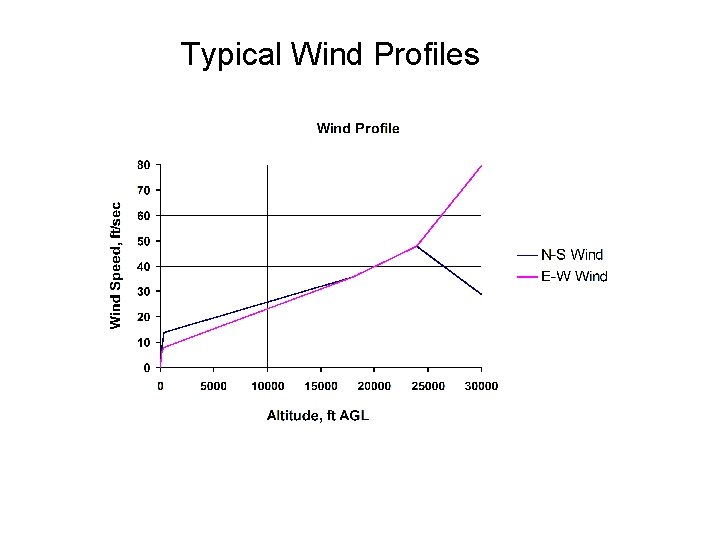
Typical Wind Profiles
Wind Compensation
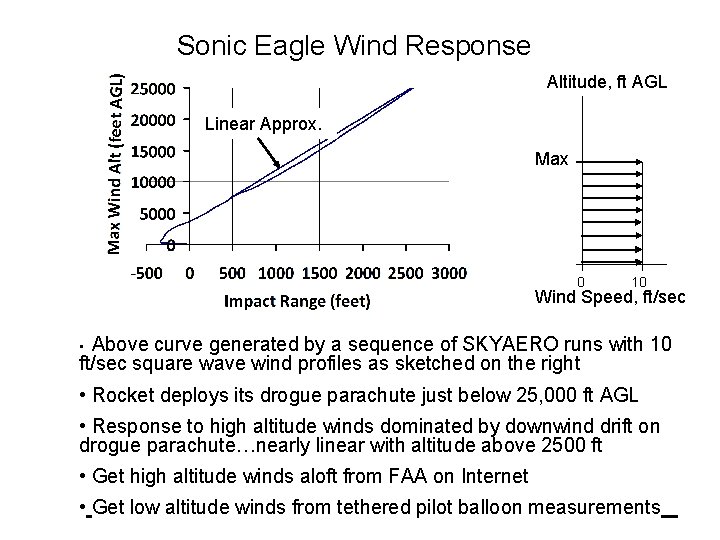
Sonic Eagle Wind Response Altitude, ft AGL Linear Approx. Max 0 10 Wind Speed, ft/sec Above curve generated by a sequence of SKYAERO runs with 10 ft/sec square wave wind profiles as sketched on the right • • Rocket deploys its drogue parachute just below 25, 000 ft AGL • Response to high altitude winds dominated by downwind drift on drogue parachute…nearly linear with altitude above 2500 ft • Get high altitude winds aloft from FAA on Internet • Get low altitude winds from tethered pilot balloon measurements
Wind Compensation • Use a precision trajectory simulation like SKYAERO 7. 6. xls – Based on Lewis* method wind response – Corrected for finite inertia near launch • Process – Enter the N – S and E –S wind profiles into SKYAERO 7. 6. xls – Enter the desired trajectory azimuth into SKYAERO 7. 6. xls – SKYAERO 7. 6. xls re-resolves the wind profiles into in plane and cross plane profiles • SKYAERO 7. 6 run list – Impact point displacement for in plane winds at QE = 90 o – Impact point displacement for cross plane winds at QE = 90 o – Impact point displacement for no wind and QE = 88 o, 86 o, 84 o, 82 o & 80 o *J. V. Lewis, “The Effect of Wind and Rotation of the Earth on Unguided Rockets”, Ballistic Research Laboratories Report No. 685, March, 1949
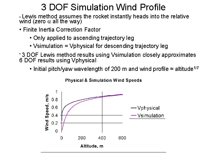
3 DOF Simulation Wind Profile • Lewis method assumes the rocket instantly heads into the relative wind (zero a all the way) • Finite Inertia Correction Factor • Only applied to ascending trajectory leg • Vsimulation = Vphysical for descending trajectory leg • 3 DOF Lewis method results using Vsimulation closely approximates 6 DOF results using Vphysical • Initial pitch/yaw wavelength of 200 m and wind profile ≈ altitude 1/7
Launcher Settings • Use LAUNCHER ANGLES. xls • Enter the SKYAERO 7. 6. xls trajectory data into LAUNCHER ANGLES. xls – Basic assumption is that for nearly vertical launches, the effects of N – S winds, E – W winds and launcher tilt angle are all approximately independent • Use LAUNCHER ANGLES. xls to compute the launcher QE and azimuth for the desired impact point location – LAUNCHER ANGLES. xls first finds in plane and cross plane QEs, – Then finds the total launcher angles assuming all angles are small
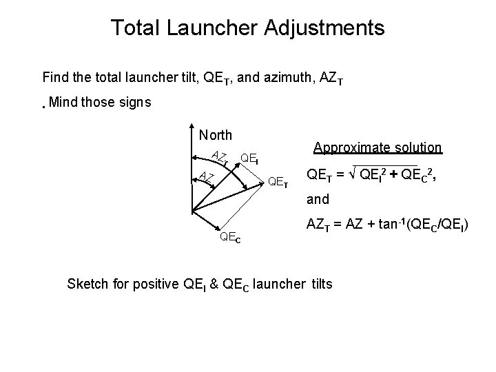
Total Launcher Adjustments Find the total launcher tilt, QET, and azimuth, AZT • Mind those signs North AZ T Approximate solution QEI AZ QET = √ QEI 2 + QEC 2, and QEC AZT = AZ + tan-1(QEC/QEI) Sketch for positive QEI & QEC launcher tilts
Summary Wind compensation of sounding rocket impact points is a mature art routinely practiced over many decades
- Slides: 22