
Winch Signalling System F B Mokgoja Section Engineer
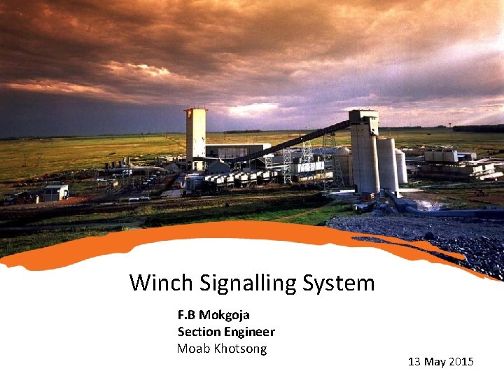
Winch Signalling System F. B Mokgoja Section Engineer Moab Khotsong 13 May 2015
Outline • Context and Purpose • Consultation Process – – • Market Research Stakeholder Engagement Design Parameters – – Functionalities of the system How it works • Technical Specifications • Installation Configuration • Challenges and Solutions • Way forward
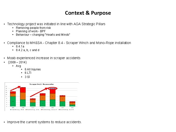
Context & Purpose • Technology project was initiated in line with AGA Strategic Pillars • Removing people from risk • Planning of work - BPF • Behaviour – changing “Hearts and Minds” • Compliance to MH&SA - Chapter 8. 4 - Scraper Winch and Mono-Rope installation • 8. 4. 1 a • 8. 4. 2 a, b, c and d • Moab experienced increase in scraper accidents • (2009 – 2014) • Avg • 6 All Injuries • 6 LTI • 3 SI • Improve the current systems to reduce accidents.
Consultation Process • Market research was conducted with these considerations: • Off the shelf- readily available • Trial tested with performance results • Reliable system • Fit for purpose system – operating environment • Competitive prices • Compatible with the current electrical standards and MH&SA regulations • The system must be plug and play and compatible with AGA winch starter box • Stakeholder Engagement • Management and organized labour discussions • Led to decision on the current system review • Management of Change • Design specifications and system functionalities were set • Different OEM invited regarding the design and functionalities • Reef Switchboard Manufacturers • WPD Groups • Bates Mining Suppliers

Design Parameters/Functionalities • Card reader facility – this prevents unauthorized operation of the winch. • Pre-start warning alarm – Audible through all the units and duration is 15 seconds, only then the driver can put the winch in motion. • Indication lights (LED) – Red/ green- this indicates whether it is safe or not to enter the scraper path • Lock out facility – on the tripped mode the driver will use his magnetic key to re-energize the system (where it tripped), only then can he put the winch in motion after pre -start warning alarm. • Emergency stop – this is achieved either by pulling the wire for longer periods or shining the cap lamp on the LED light of the unit continuously. • Signaling – for normal operation the pull wire must be pulled or cap lamp can be flashed on the unit for signaling purpose.
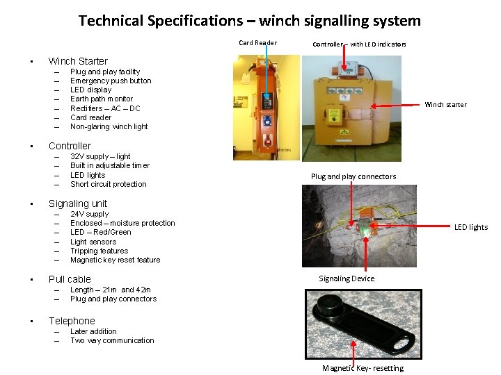
Technical Specifications – winch signalling system Card Reader • Winch Starter – – – – • 32 V supply – light Built in adjustable timer LED lights Short circuit protection Plug and play connectors 24 V supply Enclosed – moisture protection LED – Red/Green Light sensors Tripping features Magnetic key reset feature Pull cable – – • Winch starter Signaling unit – – – • Plug and play facility Emergency push button LED display Earth path monitor Rectifiers – AC – DC Card reader Non-glaring winch light Controller – – • Controller – with LED indicators LED lights Signaling Device Length – 21 m and 42 m Plug and play connectors Telephone – – Later addition Two way communication Magnetic Key- resetting
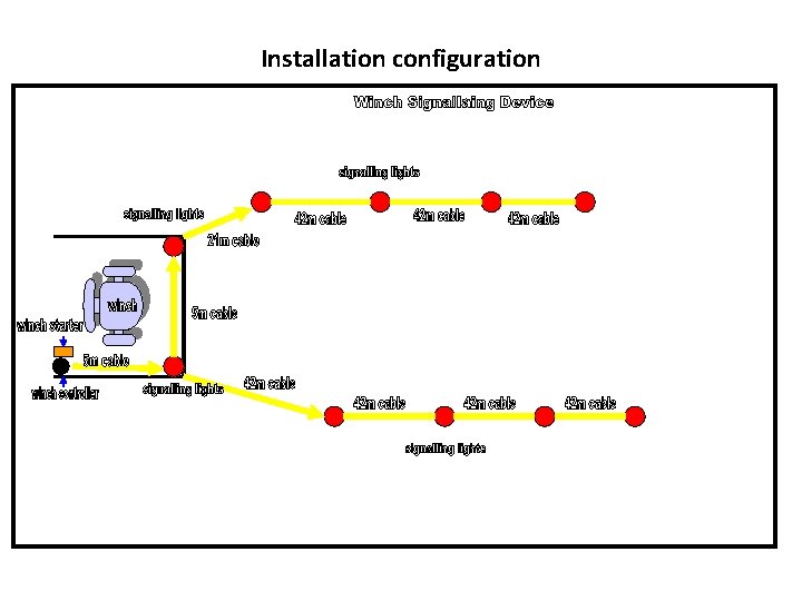
Installation configuration
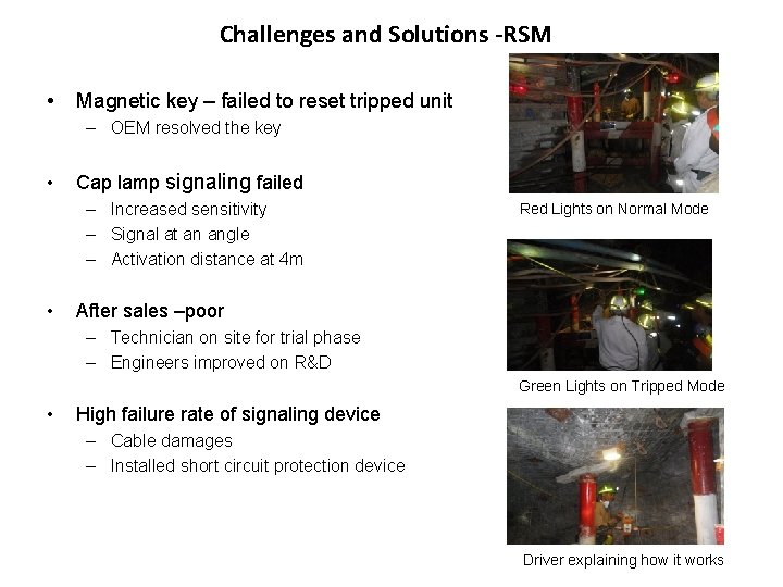
Challenges and Solutions -RSM • Magnetic key – failed to reset tripped unit – OEM resolved the key • Cap lamp signaling failed – Increased sensitivity – Signal at an angle – Activation distance at 4 m • Red Lights on Normal Mode After sales –poor – Technician on site for trial phase – Engineers improved on R&D Green Lights on Tripped Mode • High failure rate of signaling device – Cable damages – Installed short circuit protection device Driver explaining how it works
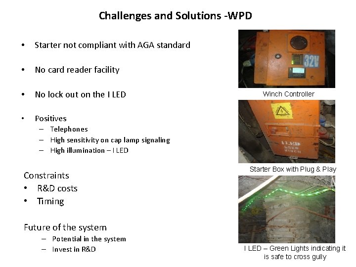
Challenges and Solutions -WPD • Starter not compliant with AGA standard • No card reader facility • No lock out on the I LED • Positives Winch Controller – Telephones – High sensitivity on cap lamp signaling – High illumination – I LED Constraints • R&D costs • Timing Starter Box with Plug & Play Future of the system – Potential in the system – Invest in R&D I LED – Green Lights indicating it is safe to cross gully
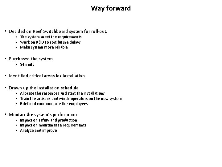
Way forward • Decided on Reef Switchboard system for roll-out. • The system meet the requirements • Work on R&D to sort future delays • Make system more reliable • Purchased the system • 54 units • Identified critical areas for installation • Drawn up the installation schedule • Allocate the resources and start the installations • Train the artisans and winch operators on the new system • Brief and communicate the employees • Monitor the system’s performance • Impact on safety and production • Impact on maintenance requirements • Analyze and improve

Questions & Discussions

Thank You
- Slides: 12