William Stallings Computer Organization and Architecture Chapter 3


 holds address of next instruction to fetch z")


 - State Diagram")


 z Functionally, similar to memory from internal viewpoint z Instead of N")
 z Receive control signals from computer z Send control signals to peripherals")


 (with cache) Buffers data transfers between system, expansion bus This approach breaks")


 seconds = 0. 0000001")


- Slides: 53
William Stallings Computer Organization and Architecture Chapter 3 Instruction Cycle Review System Buses
Architecture Review - Program Concept z Hardwired systems are inflexible y. Lots of work to re-wire, or re-toggle z General purpose hardware can do different tasks, given correct control signals z Instead of re-wiring, supply a new set of control signals Instruction Codes Instruction Interpreter Control Signals General Purpose Logic Data Results
What is a program? z Software y. A sequence of steps y. For each step, an arithmetic or logical operation is done y. For each operation, a different set of control signals is needed – i. e. an instruction
Function of Control Unit z For each operation a unique code is provided ye. g. ADD, MOVE z A hardware segment accepts the code and issues the control signals z We have a computer!
Components z Central Processing Unit y. Control Unit y. Arithmetic and Logic Unit z Data and instructions need to get into the CPU and results out y. Input/Output z Temporary storage of code and results is needed y. Main memory
Computer Components: Top Level View
Simplified Instruction Cycle z Two steps: y. Fetch y. Execute
Fetch Cycle z Program Counter (PC) holds address of next instruction to fetch z Processor fetches instruction from memory location pointed to by PC z Increment PC y. Unless told otherwise z Instruction loaded into Instruction Register (IR) z Processor interprets instruction and performs required actions
Execute Cycle z Processor-memory ydata transfer between CPU and main memory z Processor I/O y. Data transfer between CPU and I/O module z Data processing y. Some arithmetic or logical operation on data z Control y. Alteration of sequence of operations ye. g. jump z Combination of above
Hypothetical Machine z Instruction Format - Address range? Opcode Address 0 34 z Integer Format 15 - Data range? S Magnitude 0 1 15 z Registers y PC = Program Counter, IR = Instruction Register, AC = Accumulator z Partial List of Opcodes y 0001 = Load AC from Memory y 0010 = Store AC to Memory y 0101 = Add to AC from Memory
Example of Program Execution
Modifications to Instruction Cycle z Simple Example y Always added one to PC y Entire operand fetched with instruction z More complex examples y Might need more complex instruction address calculation x. Consider a 64 bit processor, variable length instructions y Instruction set design might require repeat trip to memory to fetch operand x. In particular, if memory address range exceeds word size y Operand store might require many trips to memory x. Vector calculation
Instruction Cycle State Diagram Start Here
Introduction to Interrupts z We will have more to say about interrupts later! z Interrupts are a mechanism by which other modules (e. g. I/O) may interrupt normal sequence of processing z Four general classes of interrupts y Program - e. g. overflow, division by zero y Timer x. Generated by internal processor timer x. Used in pre-emptive multi-tasking y I/O - from I/O controller y Hardware failure xe. g. memory parity error z Particularly useful when one module is much slower than another, e. g. disk access (milliseconds) vs. CPU (microseconds or faster)
Interrupt Examples
Interrupt Cycle z Added to instruction cycle z Processor checks for interrupt y Indicated by an interrupt signal z If no interrupt, fetch next instruction z If interrupt pending: y Suspend execution of current program y Save context (what does this mean? ) y Set PC to start address of interrupt handler routine y Process interrupt y Restore context and continue interrupted program
Instruction Cycle (with Interrupts) - State Diagram
Multiple Interrupts z Disable interrupts – Sequential Processing y. Processor will ignore further interrupts whilst processing one interrupt y. Interrupts remain pending and are checked after first interrupt has been processed y. Interrupts handled in sequence as they occur z Define priorities – Nested Processing y. Low priority interrupts can be interrupted by higher priority interrupts y. When higher priority interrupt has been processed, processor returns to previous interrupt
Multiple Interrupts - Sequential Disabled Interrupts – Nice and Simple
Multiple Interrupts - Nested How to handle state with an arbitrary number of interrupts?
Sample Time Sequence of Multiple Interrupts Priority 2 Printer ISR User Program t=0 Priority 5 Comm ISR Priority 4 Disk ISR t=15 t=10 t=25 t=40 t=25 t=35 Disk can’t interrupt higher priority Comm Note: Often low numbers are higher priority
Connecting z All the units must be connected z Different type of connection for different type of unit y. Memory y. Input/Output y. CPU
Memory Connection z Memory typically consists of N words of equal length addressed from 0 to N-1 z Receives and sends data y To Processor y To I/O Device z Receives addresses (of locations) z Receives control signals y Read y Write y Timing
Input/Output Connection(1) z Functionally, similar to memory from internal viewpoint z Instead of N words as in memory, we have M ports z Output y Receive data from computer y Send data to peripheral z Input y Receive data from peripheral y Send data to computer
Input/Output Connection(2) z Receive control signals from computer z Send control signals to peripherals ye. g. spin disk z Receive addresses from computer ye. g. port number to identify peripheral z Send interrupt signals (control)
CPU Connection z Sends control signals to other units z Reads instruction and data z Writes out data (after processing) z Receives (& acts on) interrupts
Buses z There a number of possible interconnection systems. The most common structure is the bus z Single and multiple BUS structures are most common z e. g. Control/Address/Data bus (PC) z e. g. Unibus (DEC-PDP) – replaced the Omnibus
What is a Bus? z A communication pathway connecting two or more devices z Usually broadcast y Everyone listens, must share the medium y Master – can read/write exclusively, only one master y Slave – everyone else. Can monitor data but not produce z Often grouped y A number of channels in one bus y e. g. 32 bit data bus is 32 separate single bit channels z Power lines may not be shown z Three major buses: data, address, control
Bus Interconnection Scheme
Data Bus z Carries data y. Remember that there is no difference between “data” and “instruction” at this level z Width is a key determinant of performance y 8, 16, 32, 64 bit y. What if the data bus is 8 bits wide but instructions are 16 bits long? y. What if the data bus is 64 bits wide but instructions are 16 bits long?
Address bus z Identify the source or destination of data y In general, the address specifies a specific memory address or a specific I/O port z e. g. CPU needs to read an instruction (data) from a given location in memory z Bus width determines maximum memory capacity of system y 8086 has 20 bit address but 16 bit word size for 64 k directly addressable address space y But it could address up to 1 MB using a segmented memory model x. RAM: 0 – BFFFF, ROM: C 0000 - FFFFF x. DOS only allowed first 640 K to be used, remaining memory for BIOS, hardware controllers. Needed High-Memory Manager to “break the 640 K barrier”
Control Bus z Control and timing information y Determines what modules can use the data and address lines y If a module wants to send data, it must (1) obtain permission to use the bus, and (2) transfer data – which might be a request for another module to send data z Typical control lines y Memory read y Memory write y I/O read y I/O write y Interrupt request y Interrupt ACK y Bus Request y Bus Grant y Clock signals
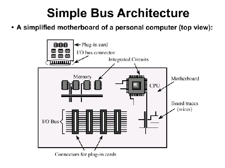
Big and Yellow? z What do buses look like? y. Parallel lines on circuit boards y. Ribbon cables y. Strip connectors on mother boards xe. g. PCI y. Sets of wires z Limited by physical proximity – time delays, fan out, attenuation are all factors for long buses
Single Bus Problems z Lots of devices on one bus leads to: y Propagation delays x. Long data paths mean that co-ordination of bus use can adversely affect performance – bus skew, data arrives at slightly different times x. If aggregate data transfer approaches bus capacity. Could increase bus width, but expensive y Device speed x. Bus can’t transmit data faster than the slowest device x. Slowest device may determine bus speed! • Consider a high-speed network module and a slow serial port on the same bus; must run at slow serial port speed so it can process data directed for it y Power problems z Most systems use multiple buses to overcome these problems
Traditional (ISA) (with cache) Buffers data transfers between system, expansion bus This approach breaks down as I/O devices need higher performance
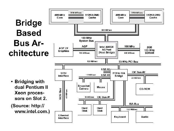
High Performance Bus – Mezzanine Architecture Addresses higher speed I/O devices by moving up in the hierarchy
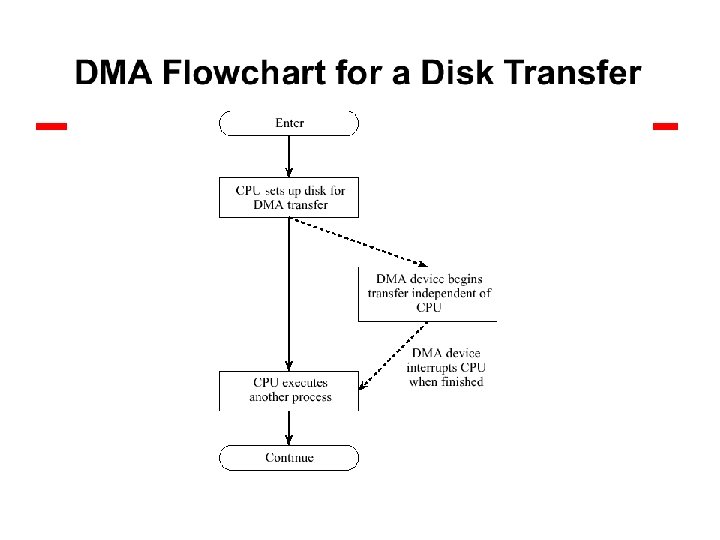
Direct Memory Access
Bus Types z Dedicated y. Separate data & address lines z Multiplexed y. Shared lines y. Consider shared address, data lines x. Need separate Address valid or Data valid control line x. Time division multiplexing in this case y. Advantage - fewer lines y. Disadvantages x. More complex control x. Ultimate performance
Bus Arbitration z More than one module may want to control the bus ye. g. I/O module may need to send data to memory and to the CPU z But only one module may control bus at one time y. Arbitration decides who gets to use the bus y. Arbitration must be fast or I/O devices might lose data z Arbitration may be centralized or distributed
Centralized Arbitration z Single hardware device is responsible for allocating bus access y. Bus Controller y. Arbiter z May be part of CPU or separate
Distributed Arbitration z No single arbiter z Each module may claim the bus z Proper control logic on all modules so they behave to share the bus z Purpose of both distributed and centralized is to designate the master z The recipient of a data transfer is the slave z Many types of arbitration algorithms: round-robin, priority, etc.
Daisy Chaining of devices What if a device breaks? Devices to left higher priority
Bus Arbitration Implementations – Centralized z Centralized y If a device wants the bus, assert bus request y Arbiter decides whether or not to send bus grant y Bus grant travels through daisy-chain of devices y If device wants the bus, it uses it and does not propagate bus grant down the line. Otherwise it propagates the bus grant. y Electrically close devices to arbiter get first priority z Centralized with Multiple Priority Levels y Can add multiple priority levels, grants, for more flexible system. Arbiter can issue bus grant on only highest priority line
Bus Arbitration Implementation - Decentralized z Decentralized y. If don’t want the bus, propagate bus grant down the line y. To acquire bus, see if bus is idle and bus grant is on x. If bus grant is off, may not become master, propagate negative bus grant x. If bus grant is on, propagate negative bus grant y. When dust settles, only one device has bus grant y. Asserts busy on and begins transfer y. Leftmost device that wants the bus gets it
Timing z Co-ordination of events on bus z Synchronous y. Events determined by clock signals y. Control Bus includes clock line y. A single 1 -0 is a bus cycle y. All devices can read clock line y. Usually sync on leading edge y. Usually a single cycle for an event
100 million cycles per second 1 cycle in (1/100, 000) seconds = 0. 0000001 s = 10 ns In reality, the clock is a bit more sawtoothed
Synchronous Timing Diagram Read Operation Timing Indicates read/address lines valid, noticed by memory Indicates we want to read, not write Address from memory we want delay Data from memory Indicates data lines valid
Synchronous - Disadvantages z Although synchronous clocks are simple, there are some disadvantages y. Everything done in multiples of clock, so something finishing in 3. 1 cycles takes 4 cycles y. With a mixture of fast and slow devices, we have to wait for the slowest device x. Faster devices can’t run at their capacity, all devices are tied to a fixed clock rate x. Consider memory device speed faster than 10 ns, no speedup increase for 100 Mhz clock z One solution: Use asynchronous bus
Asynchronous Bus z No clock z Occurrence of one event on the bus follows and depends on a previous event z Requires tracking of state, hard to debug, but potential for higher performance z Also used with networking y. Problem with “drift” and loss of synchronization y. Some use self-clocking codes, e. g. Ethernet
Asynchronous Timing Diagram Asserted once read/address lines stabilize Deasserted when finished reading Master sync Slave = memory, ACK’s master sync Master reads the data from the data bus Slave sync Slave places requested data on bus