
William Stallings Computer Organization and Architecture 7 th
- Slides: 54
William Stallings Computer Organization and Architecture 7 th Edition Chapter 7 Input/Output
Input/Output Problems • Wide variety of peripherals —Delivering different amounts of data —At different speeds —In different formats • All slower than CPU and RAM • Need I/O modules
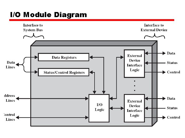
Input/Output Module • Interface to CPU and Memory • Interface to one or more peripherals
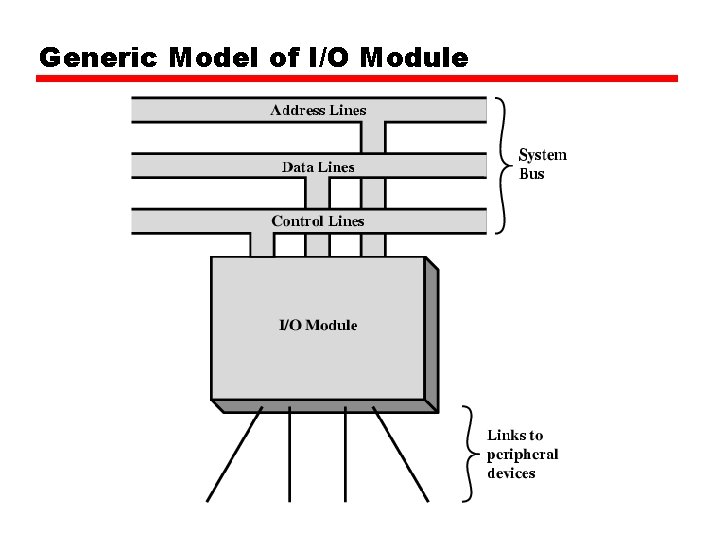
Generic Model of I/O Module
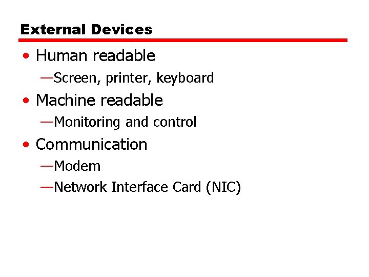
External Devices • Human readable —Screen, printer, keyboard • Machine readable —Monitoring and control • Communication —Modem —Network Interface Card (NIC)
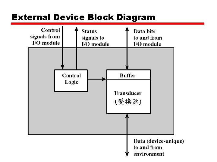
External Device Block Diagram (變換器)
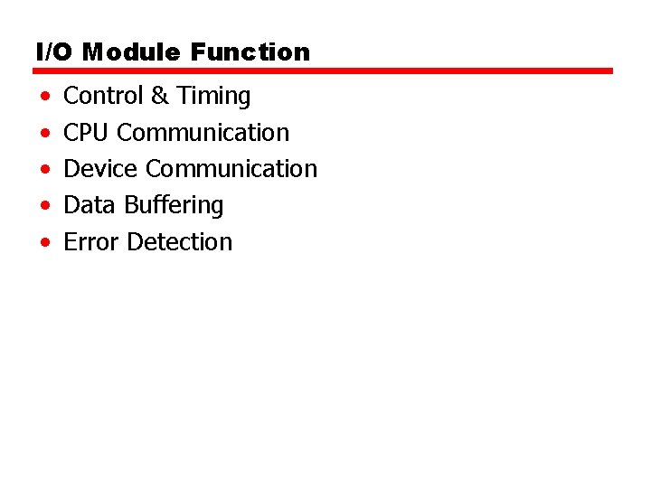
I/O Module Function • • • Control & Timing CPU Communication Device Communication Data Buffering Error Detection
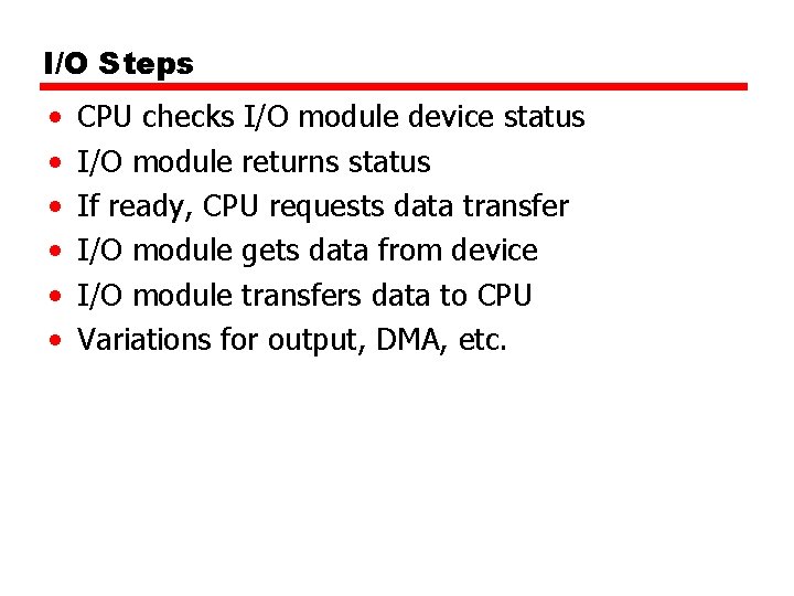
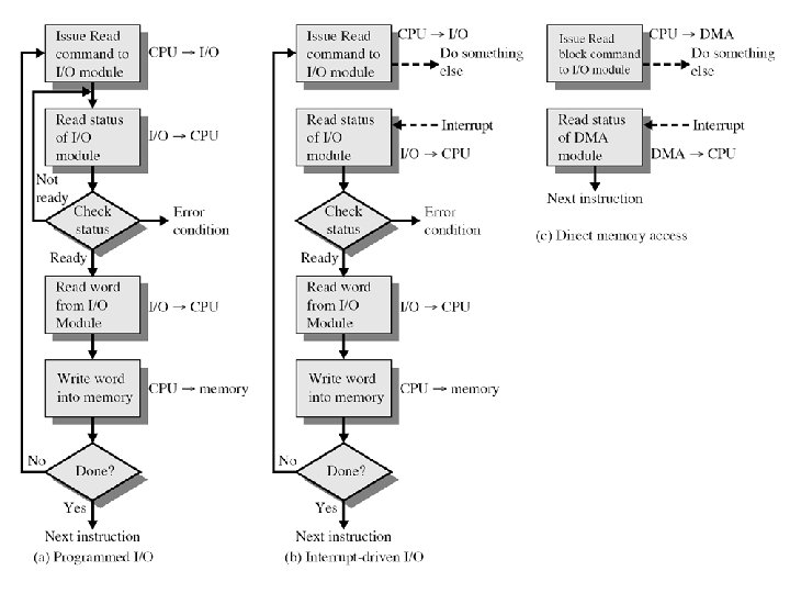
I/O Steps • • • CPU checks I/O module device status I/O module returns status If ready, CPU requests data transfer I/O module gets data from device I/O module transfers data to CPU Variations for output, DMA, etc.
I/O Module Diagram
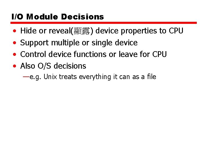
I/O Module Decisions • • Hide or reveal(顯露) device properties to CPU Support multiple or single device Control device functions or leave for CPU Also O/S decisions —e. g. Unix treats everything it can as a file
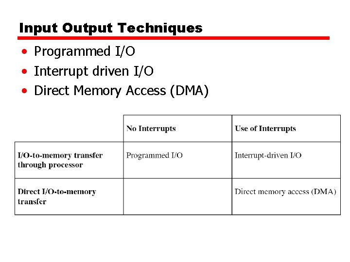
Input Output Techniques • Programmed I/O • Interrupt driven I/O • Direct Memory Access (DMA)
Programmed I/O • CPU has direct control over I/O —Sensing status —Read/write commands —Transferring data • CPU waits for I/O module to complete operation • Wastes CPU time
Programmed I/O - detail • • CPU requests I/O operation I/O module performs operation I/O module sets status bits CPU checks status bits periodically I/O module does not inform CPU directly I/O module does not interrupt CPU may wait or come back later
I/O Commands • CPU issues address —Identifies module (& device if >1 per module) • CPU issues command —Control - telling module what to do – e. g. spin up disk —Test - check status – e. g. power? Error? —Read/Write – Module transfers data via buffer from/to device
Addressing I/O Devices • Under programmed I/O data transfer is very like memory access (CPU viewpoint) • Each device given unique identifier • CPU commands contain identifier (address)
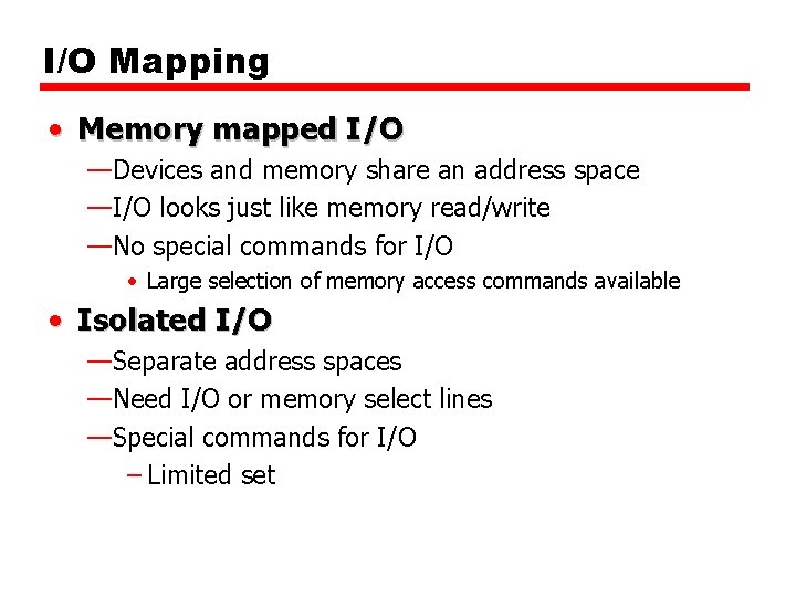
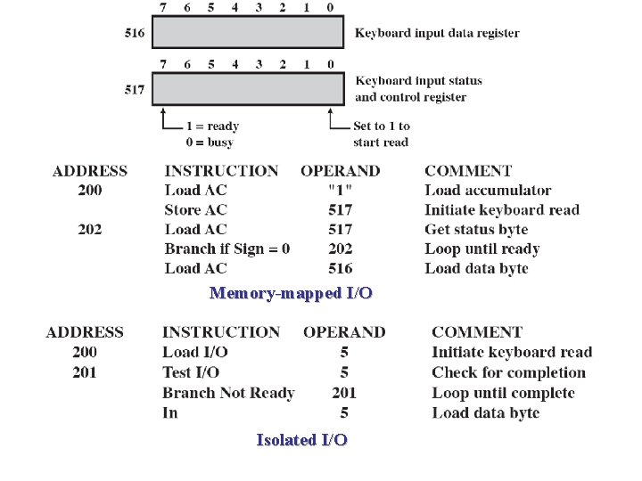
I/O Mapping • Memory mapped I/O —Devices and memory share an address space —I/O looks just like memory read/write —No special commands for I/O • Large selection of memory access commands available • Isolated I/O —Separate address spaces —Need I/O or memory select lines —Special commands for I/O – Limited set
Memory-mapped I/O Isolated I/O
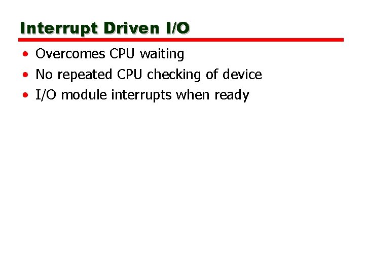
Interrupt Driven I/O • Overcomes CPU waiting • No repeated CPU checking of device • I/O module interrupts when ready
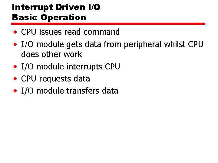
Interrupt Driven I/O Basic Operation • CPU issues read command • I/O module gets data from peripheral whilst CPU does other work • I/O module interrupts CPU • CPU requests data • I/O module transfers data
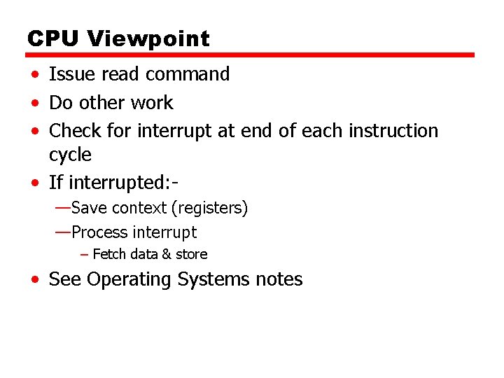
CPU Viewpoint • Issue read command • Do other work • Check for interrupt at end of each instruction cycle • If interrupted: —Save context (registers) —Process interrupt – Fetch data & store • See Operating Systems notes
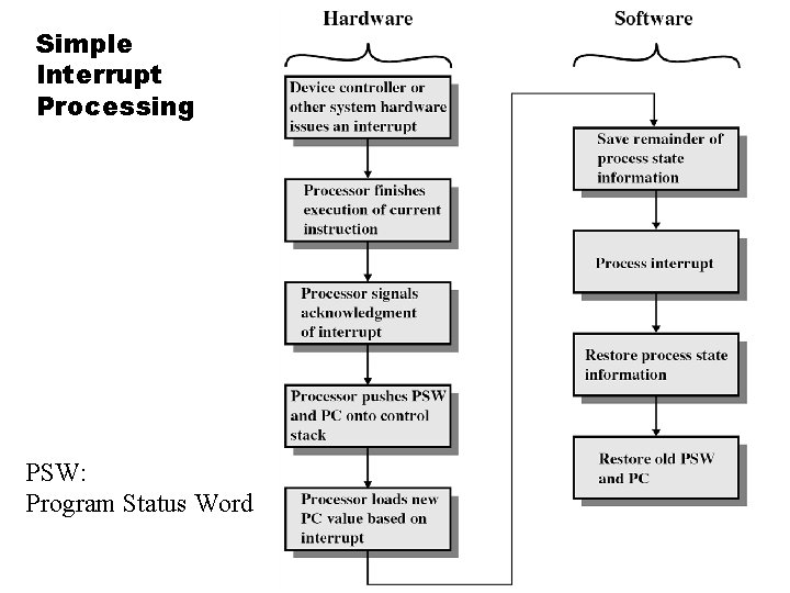
Simple Interrupt Processing PSW: Program Status Word
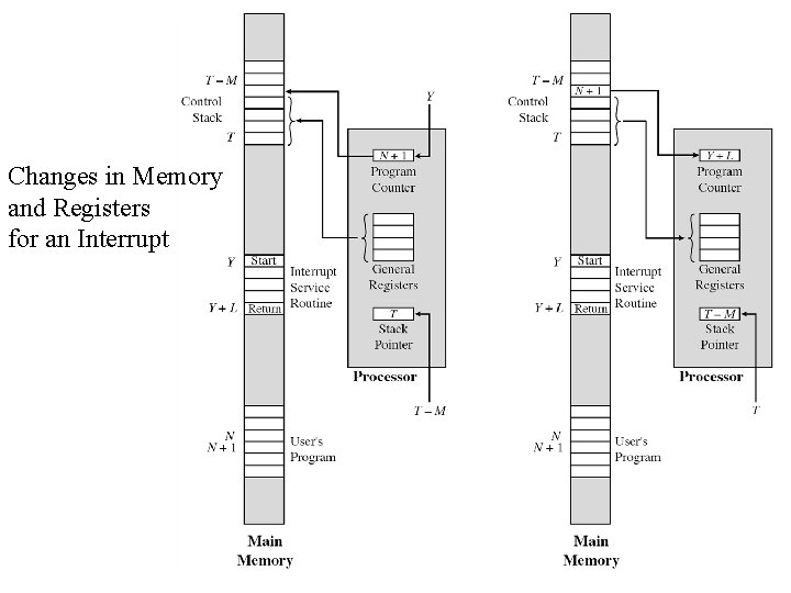
Changes in Memory and Registers for an Interrupt
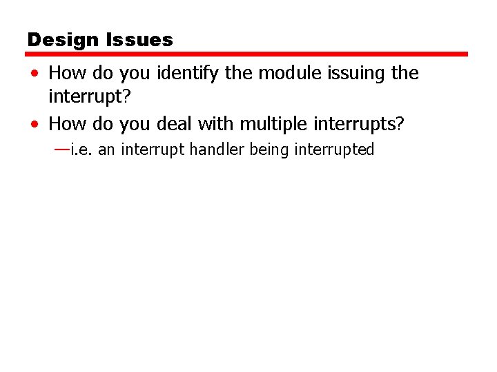
Design Issues • How do you identify the module issuing the interrupt? • How do you deal with multiple interrupts? —i. e. an interrupt handler being interrupted
Identifying Interrupting Module • • Multiple Interrupt Lines Software Poll Daisy Chain (Hardware poll) Bus Arbitration
Identifying Interrupting Module (1) • Multiple Interrupt Lines —Each interrupt line may have multiple I/O modules —Limits number of devices • Software poll —CPU asks each module in turn —Slow
Identifying Interrupting Module (2) • Daisy Chain or Hardware poll —Interrupt Acknowledge sent down a chain —Module responsible places vector on bus —CPU uses vector to identify handler routine • Bus Master —Module must claim the bus before it can raise interrupt —e. g. PCI & SCSI Daisy: 雛菊花 Daisy Chain: 菊環 菊鏈
Multiple Interrupts • Each interrupt line has a priority • Higher priority lines can interrupt lower priority lines • If bus mastering only current master can interrupt
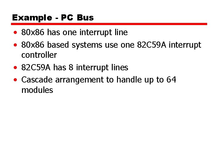
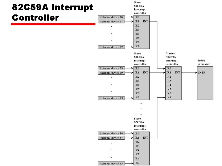
Example - PC Bus • 80 x 86 has one interrupt line • 80 x 86 based systems use one 82 C 59 A interrupt controller • 82 C 59 A has 8 interrupt lines • Cascade arrangement to handle up to 64 modules
82 C 59 A Interrupt Controller
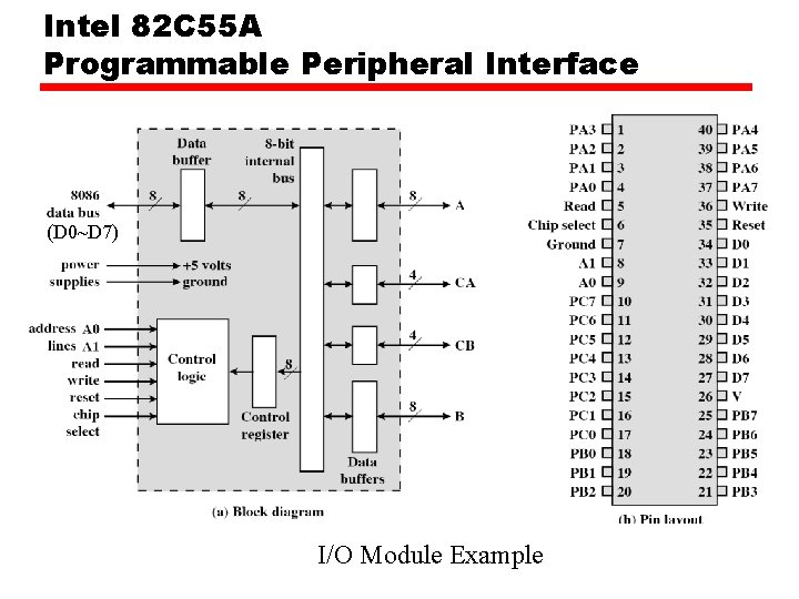
Intel 82 C 55 A Programmable Peripheral Interface (D 0~D 7) I/O Module Example
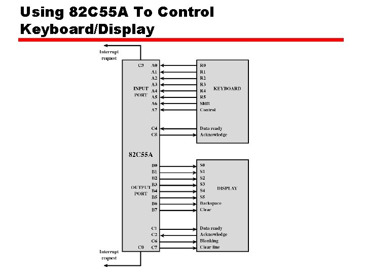
Using 82 C 55 A To Control Keyboard/Display
Direct Memory Access • Interrupt driven and programmed I/O require active CPU intervention —Transfer rate is limited —CPU is tied up • DMA is the answer
DMA Function • Additional Module (hardware) on bus • DMA controller takes over from CPU for I/O
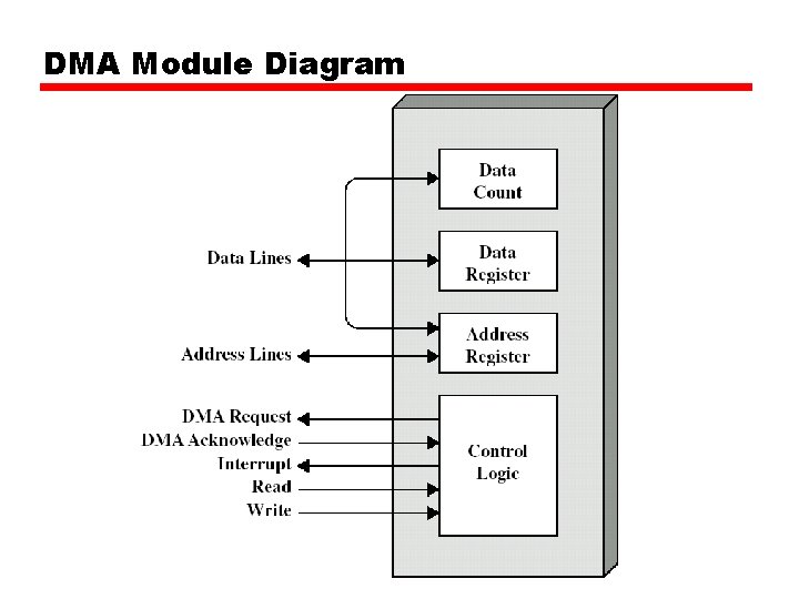
DMA Module Diagram
DMA Operation • CPU tells DMA controller: —Read/Write —Device address —Starting address of memory block for data —Amount of data to be transferred • CPU carries on with other work • DMA controller deals with transfer • DMA controller sends interrupt when finished
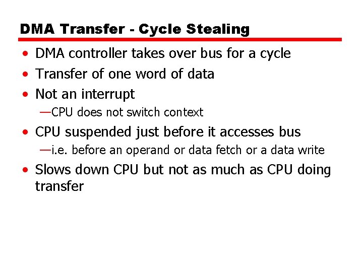
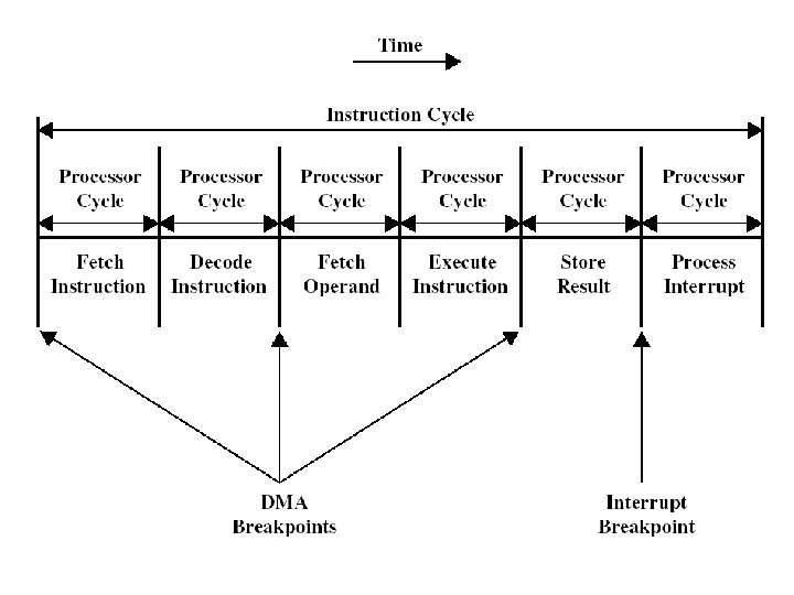
DMA Transfer - Cycle Stealing • DMA controller takes over bus for a cycle • Transfer of one word of data • Not an interrupt —CPU does not switch context • CPU suspended just before it accesses bus —i. e. before an operand or data fetch or a data write • Slows down CPU but not as much as CPU doing transfer
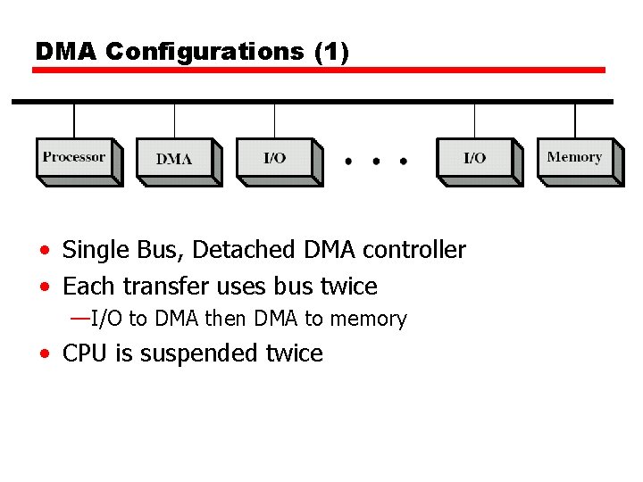
DMA Configurations (1) • Single Bus, Detached DMA controller • Each transfer uses bus twice —I/O to DMA then DMA to memory • CPU is suspended twice
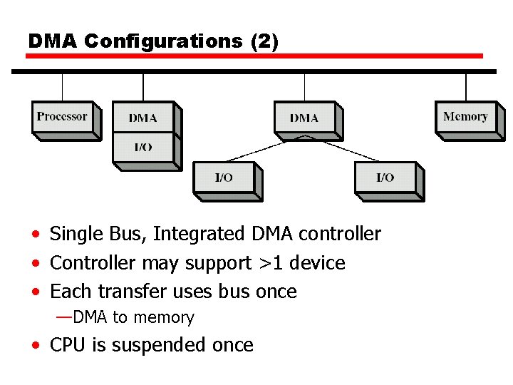
DMA Configurations (2) • Single Bus, Integrated DMA controller • Controller may support >1 device • Each transfer uses bus once —DMA to memory • CPU is suspended once
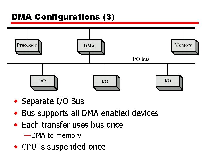
DMA Configurations (3) • Separate I/O Bus • Bus supports all DMA enabled devices • Each transfer uses bus once —DMA to memory • CPU is suspended once
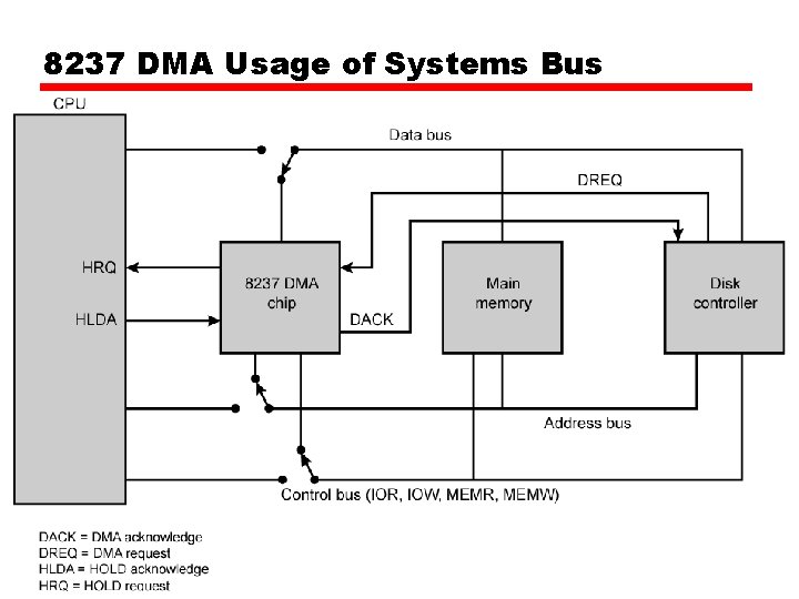
8237 DMA Usage of Systems Bus
I/O Channels • I/O devices getting more sophisticated —e. g. 3 D graphics cards • CPU instructs I/O controller to do transfer • I/O controller does entire transfer • Improves speed —Takes load off CPU —Dedicated processor is faster • I/O Channel — Execute I/O instructions, stored in main memory — I/O processor Sophisticated: 複雜, 精密的
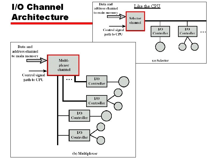
I/O Channel Architecture Like the CPU
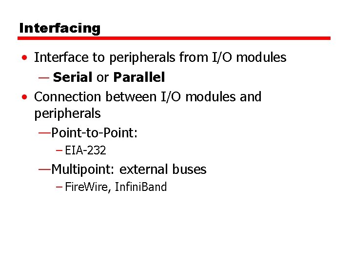
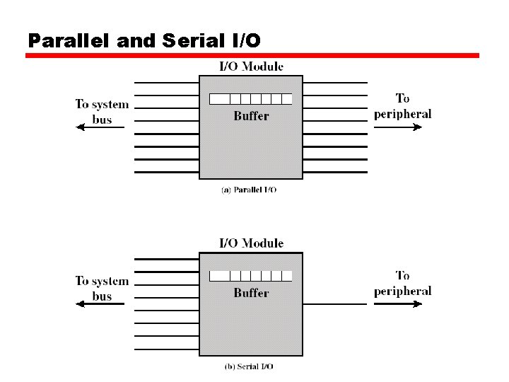
Interfacing • Interface to peripherals from I/O modules — Serial or Parallel • Connection between I/O modules and peripherals —Point-to-Point: – EIA-232 —Multipoint: external buses – Fire. Wire, Infini. Band
Parallel and Serial I/O
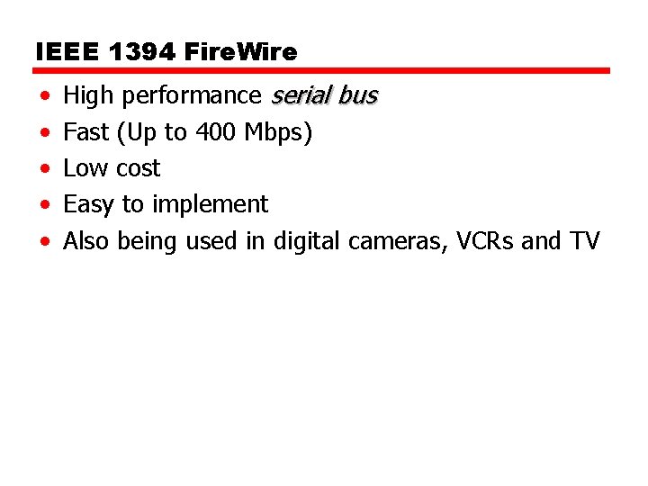
IEEE 1394 Fire. Wire • • • High performance serial bus Fast (Up to 400 Mbps) Low cost Easy to implement Also being used in digital cameras, VCRs and TV
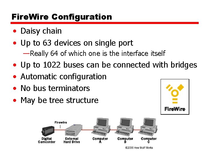
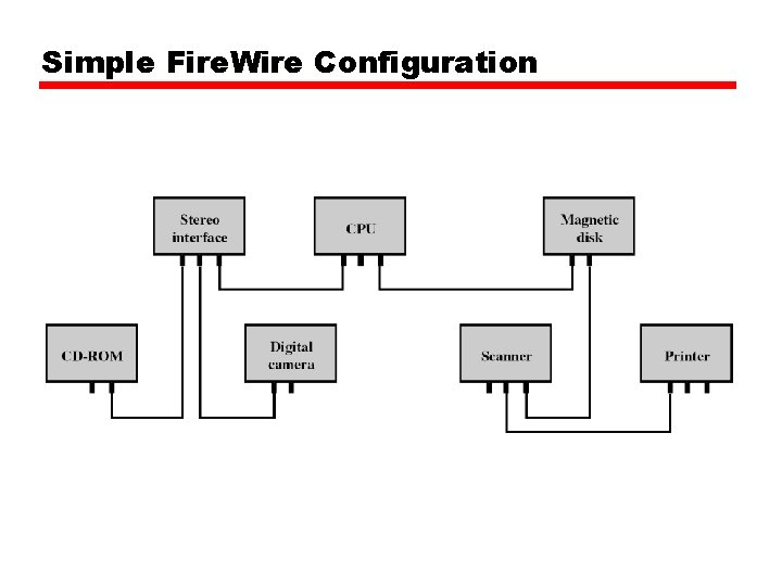
Fire. Wire Configuration • Daisy chain • Up to 63 devices on single port —Really 64 of which one is the interface itself • • Up to 1022 buses can be connected with bridges Automatic configuration No bus terminators May be tree structure
Simple Fire. Wire Configuration
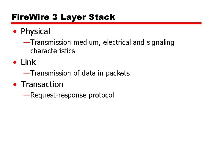
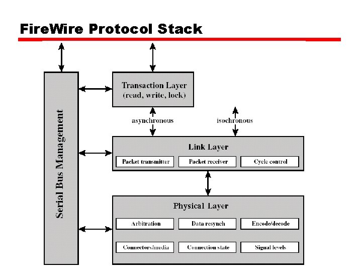
Fire. Wire 3 Layer Stack • Physical —Transmission medium, electrical and signaling characteristics • Link —Transmission of data in packets • Transaction —Request-response protocol
Fire. Wire Protocol Stack Physical
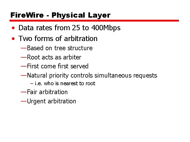
Fire. Wire - Physical Layer • Data rates from 25 to 400 Mbps • Two forms of arbitration —Based on tree structure —Root acts as arbiter —First come first served —Natural priority controls simultaneous requests – i. e. who is nearest to root —Fair arbitration —Urgent arbitration
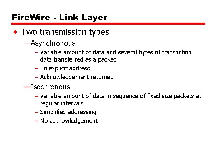
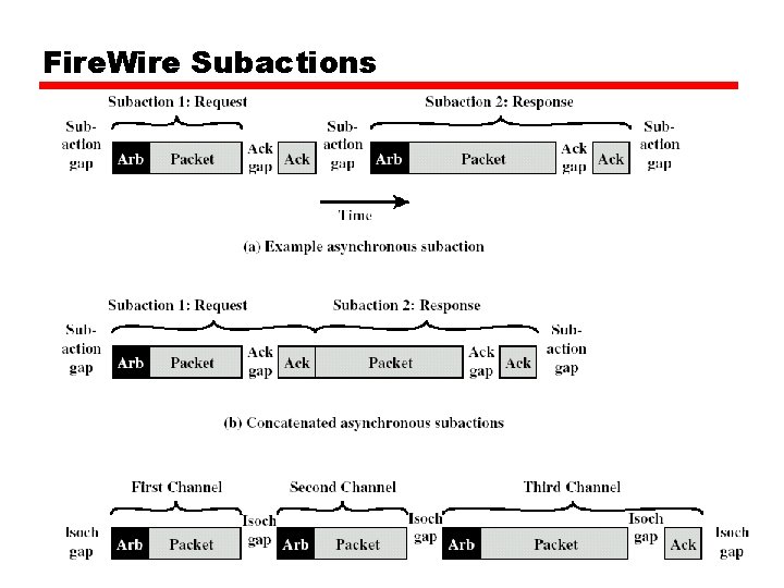
Fire. Wire - Link Layer • Two transmission types —Asynchronous – Variable amount of data and several bytes of transaction data transferred as a packet – To explicit address – Acknowledgement returned —Isochronous – Variable amount of data in sequence of fixed size packets at regular intervals – Simplified addressing – No acknowledgement
Fire. Wire Subactions