When a pipe drainage system is being designed


When a pipe drainage system is being designed, the following elements must be determined: -a- lay-out (alignment) of laterals and collectors; this must be adapted to the topographical features of the area and other conditions. b- spacing and depth of laterals; these are primary factors in the control of the groundwater table. c- diameter and gradients of lateral and collector pipes; these must ensure the proper evacuation of the water taken up by the laterals. -

When the hydraulic design of a drain pipe system is being considered one faces such question as: 1 - What area can be drained by a pipe line of given diameter laid at a given slope, assuming a certain specific discharge? 2 - What pipe diameter is needed for a pipe line of given length, laid at a given slope, with given drain spacing and specific discharge?

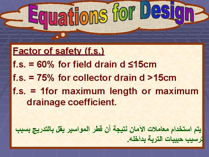
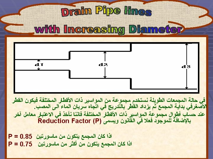
To provide answers to such questions, one must consider the following items: 1 - Basic flow equations (uniform flow) for different types of drain pipes. 2 - Flow equations that take into account the fact that the flow in a drain pipe line increases in the direction of flow as the drain takes up water over its entire length (non-uniform flow). 3 - Gradient and slope of pipe line. 4 - A safety factor to allow for some decrease in capacity due to a certain degree of sedimentation. 5 - A drain composed of sections of increasing diameter in the direction of flow.

1 - The case of uniform flow in circular conduits running full. 2 - The discharge and hydraulic gradient are constants at all sections of the pipe.

1 - The flow rate Q gradually increases from Q=0 at the upstream end to Q=q. BL at the outflow where q is the drainage coefficient, B is the width of area to be drained pipe line. 2 - The flow rate gradually increases in the direction of flow. 3 - The hydraulic gradient increases also.
: ﺗﺴﺘﺨﺪﻡ ﻓﻲ ﺗﺼﻤﻴﻢ ﻣﻮﺍﺳﻴﺮ ﺍﻟﺼﺮﻑ ﺍﻟﻤﻠﺴﺎﺀ")
1 - Uniform Flow: A- Wesseling Equations (Smooth): ﺗﺴﺘﺨﺪﻡ ﻓﻲ ﺗﺼﻤﻴﻢ ﻣﻮﺍﺳﻴﺮ ﺍﻟﺼﺮﻑ ﺍﻟﻤﻠﺴﺎﺀ Clay, Cement, Smooth plastic pipes Ql = q. BL = f. s. ( 50 d 2. 714 S 0. 572 ) q: Drainage coefficient factor (m/sec) B: Spacing between pipe drains (m). L: Length of pipe drain (m). f. s. : Factor of Safety. d: Pipe diameter (m). S: Drain slope (dimensionless).
: ( ﺗﺴﺘﺨﺪﻡ ﻓﻲ ﺗﺼﻤﻴﻢ ﻣﻮﺍﺳﻴﺮ ﺍﻟﺼﺮﻑ ﺍﻟﺒﻼﺳﺘﻴﻚ ﺍﻟﻤﻤﻮﺟﺔ )ﺫﺍﺕ ﺗﻌﺎﺭﻳﺞ")
B- Manning Equations (Corrugated): ( ﺗﺴﺘﺨﺪﻡ ﻓﻲ ﺗﺼﻤﻴﻢ ﻣﻮﺍﺳﻴﺮ ﺍﻟﺼﺮﻑ ﺍﻟﺒﻼﺳﺘﻴﻚ ﺍﻟﻤﻤﻮﺟﺔ )ﺫﺍﺕ ﺗﻌﺎﺭﻳﺞ Corrugated plastic PVC Ql = q. BL = f. s. ( 22 d 2. 667 S 0. 5 ) 2 - Non-Uniform Flow: A- Wesseling Equations (Smooth): Ql = q. BL = f. s. ( 89 d 2. 714 S 0. 572 ) B- Manning Equations (Corrugated): Ql = q. BL = f. s. ( 38 d 2. 667 S 0. 5 )

1 - The pipes used for lateral drains are cement and corrugated PVC pipes with internal diameters 100 and 72 mm respectively. Find the maximum length with each type for a drainage rate of 3 mm/day and drain spacing 50 m in the following cases: a- drain slope 0. 1% b- drain slope 0. 2 %

1 - Cement Pipe Ql = q. BL = f. s. ( 89 d 2. 714 S 0. 572 ) (3*50*L)/(1000*24*3600) = 1*89 * (0. 1)2. 714 S 0. 572 L= 99040 S 0. 572 S (%) L (m) 0. 1 1904. 6 0. 2 2831. 4

2 - PVC Pipe Ql = q. BL = f. s. ( 38 d 2. 667 S 0. 5 ) (3*50*L)/(1000*24*3600) = 1*38 * (0. 072)2. 667 S 0. 5 L= 1961. 34 S 0. 5 S (%) L (m) 0. 1 62 0. 2 87

Find the maximum drainage coefficient, which can be drained from an area with corrugated plastic pipe of a diameter 72 mm at a spacing of 60 m and length 200 m if the slope of the drain is: a- 10 cm per 100 m b- 0. 2% Solution Ql = q. BL = f. s. ( 38 d 2. 667 S 0. 5 ) a- q * 60 * 200 = 1* 38 * (0. 072)2. 667 * (10/10000)0. 5 q = 9*10 -8 m/sec * 1000 * 24 * 60 = 7. 76 mm/day b- q * 60 * 200 = 1 * 38 * (0. 072)2. 667 * (0. 2/100)0. 5 q = 1. 3*10 -7 m/sec * 1000 * 86400 = 0. 97 mm/day

What is the maximum area which can be drained with pipe of constant diameter when the allowable slope should not exceed 0. 04% and the drainage coefficient is 4 mm/day? The pipes are of 100, 150, and 200 mm diameter and they are: a- corrugated plastic tubes. b- smooth pipes.

Max. area f. s. =1. 0 A- Corrugated Plastic tubes: Ql = q. BL = f. s. ( 38 d 2. 667 S 0. 5 ) (4/1000)*(BL / 24*60*60) = 38 d 2. 667 (0. 04/100)0. 5 d 0. 15 0. 2 BL (fed. ) 35340 104208 224447

B- Smooth Pipes Ql = q. BL = f. s. ( 89 d 2. 714 S 0. 572 ) (4/1000)*(BL / 24*60*60) = 89 d 2. 714 (0. 04/100)0. 572 d 0. 15 BL (fed. ) 42288 127096 0. 2 277470

Design a corrugated plastic collector drain with a slope of 10 cm per 100 m and increasing diameters 125, 160, and 200, if the drainage coefficient is 3 mm/day. The length of laterals on each side is 200 m and the total length of the collector is 650 m. What is the drop in elevation for a pipe of diameter of 350 mm to transport the flow of this area to a lake at 300 m from the outlet?

Ql = q. BL = f. s. ( 38 d 2. 667 S 0. 5 ) (3 / 1000*24*60*60) * 400 * L = f. s. * 38 * d 2. 667 * (0. 001)0. 5 L = f. s. (86519. 916 d 2. 667 ) Diameter (m) 0. 125 0. 16 0. 2 f. s. 0. 6 0. 75 Max. L (m) 202. 64054 489. 289 887. 2 (0. 75) L (m) 151. 98 366. 967 665. 4 Approximate L (m) 150 365 650 Each length (m) 150 250 Total length (m) 650

Transporting Case: Ql = q. BL = f. s. ( 22 d 2. 667 S 0. 5 ) (3 / 1000*24*60*60) * 400 * 650 = 0. 75 * 22 * (0. 35)2. 667 * (K/300)0. 5 K = 0. 0242804 m The drop in elevation (k) = 24. 28 mm

Design a corrugated plastic collector with increasing diameters 125, 150, 200 and 260 mm are used and the pipe slope is 0. 08%. The drainage rate is 4 mm/day and the width of the area served is 350 m. What is the total length of the collector in this case?

Ql = q. BL = f. s. ( 38 d 2. 667 S 0. 5 ) (4 / 1000*24*60*60) * 350*L = 38 * d 2. 667 *(0. 08/100) S 0. 5 * f. s. Diameter (m) 0. 125 0. 15 0. 26 f. s. 0. 6 0. 75 Max. L (m) 155. 4 315. 8 680. 2 1369. 3 0. 75 L (m) 116. 55 236 510 1027 Approximate L (m) 115 235 510 1025

A concrete collector with a diameter 20 cm, a length 600 m laid at slope 0. 04% drains an area 300 m wide with discharge rate 10 mm/day. What will be the over-pressure at the upstream end of the collector if its capacity is to be set at 75%.

Ql = q. BL = f. s. ( 89 d 2. 714 S 0. 572 ) (10 / 1000*24*60*60) * 300 * 600 = 0. 75 * 89 * (0. 2)2. 714 S’ 0. 572 S’ = 1. 54*10 -3 S’ = Z/L = Z/600 Z = 0. 924 i = S = H/L H = S*L = (0. 04/100) * 600 H = 0. 24 m Over Pressure = Z – H = 0. 924 – 0. 24 = 0. 684 m = 68. 4 cm

Calculate the area to be saved by a cement collector pipe in the tile drainage system according to the following data: drainage coefficient = 4 mm/day, collector pipe diameter =20 cm, average slope = 4 cm/100 m.

Smooth pipe, q=4 mm/day, d=20 cm, S= 4*10 -4 Ql = q. BL = f. s. ( 89 d 2. 714 S 0. 572 ) (4 / 1000*24*60*60) BL = 0. 75 * 89 * (0. 2)2. 714 *(4*10 -4)0. 572 BL = 208103. 2 m 2 = 49. 5 fed

A collector drain in a composite system has a total length of 750 m and slope 0. 04% serves an area with a width 400 m. If the drainage coefficient is 2. 0 mm/day and pipes available are corrugated plastic tubes with diameters equal to 150, 200, and 250 mm. Find the maximum length that can be used of each size to make a collector with increasing diameter.

S = 0. 04%, B=400 m, L=750 m, q=2 mm/day Ql = q. BL = f. s. ( 38 d 2. 667 S 0. 5 ) (2 / 1000*24*60*60)*400*L = 38*d 2. 667*(0. 04/100)S 0. 5 * f. s. 1. 22 * 10 -5 L = f. s. * d 2. 667 Diameter (m) 0. 15 0. 25 f. s. 0. 6 0. 75 Max. L (m) 312. 86 842. 2 1526. 9 0. 75 L (m) 234. 6 631. 66 1145. 2 Approximate L (m) 230 630 1145 Each length (m) 230 400 515 Total length (m) 750
- Slides: 28