What is Sequence Diagram UML Sequence Diagrams are


 down the page.")


 represents the period during which an")


 gives the ability to attach various remarks to elements.")
 fragments. Sequence fragments make")


- Slides: 25
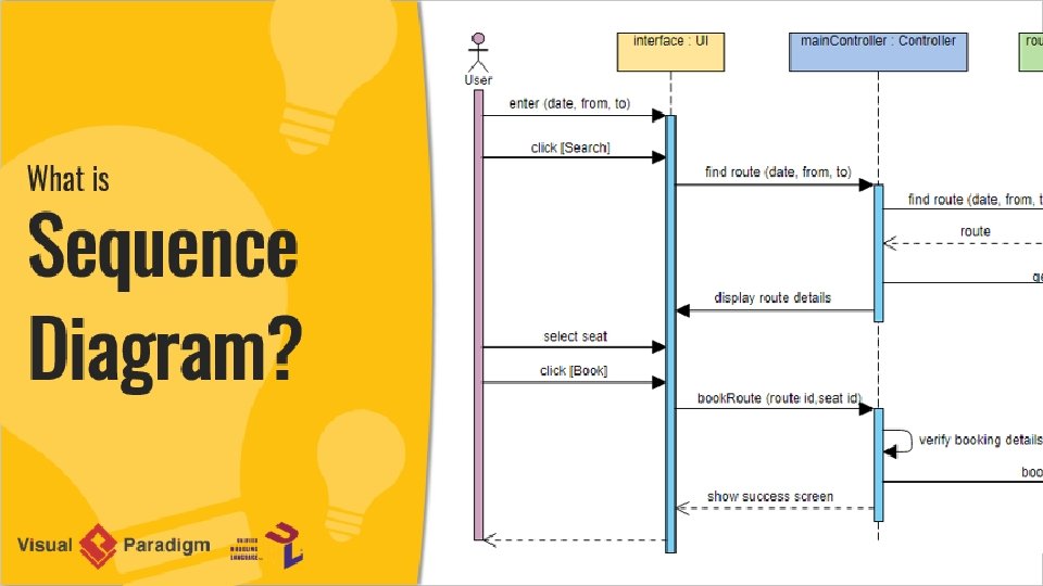
What is Sequence Diagram? • UML Sequence Diagrams are interaction diagrams that detail how operations are carried out. They capture the interaction between objects in the context of a collaboration. • Sequence Diagrams are time focus and they show the order of the interaction visually by using the vertical axis of the diagram to represent time what messages are sent and when.
Sequence Diagrams captures: • the interaction that takes place in a collaboration that either realizes a use case or an operation (instance diagrams or generic diagrams) • high-level interactions between user of the system and the system, between the system and other systems, or between subsystems (sometimes known as system sequence diagrams)
Purpose of Sequence Diagram • Model high-level interaction between active objects in a system • Model the interaction between object instances within a collaboration that realizes a use case • Model the interaction between objects within a collaboration that realizes an operation • Either model generic interactions (showing all possible paths through the interaction) or specific instances of a interaction (showing just one path through the interaction)
Sequence Diagrams at a Glance • Sequence Diagrams show elements as they interact over time and they are organized according to object (horizontally) and time (vertically): • Object Dimension • The horizontal axis shows the elements that are involved in the interaction • Conventionally, the objects involved in the operation are listed from left to right according to when they take part in the message sequence. However, the elements on the horizontal axis may appear in any order
Time Dimension • The vertical axis represents time proceedings (or progressing) down the page. Note that: • Time in a sequence diagram is all a about ordering, not duration. The vertical space in an interaction diagram is not relevant for the duration of the interaction.
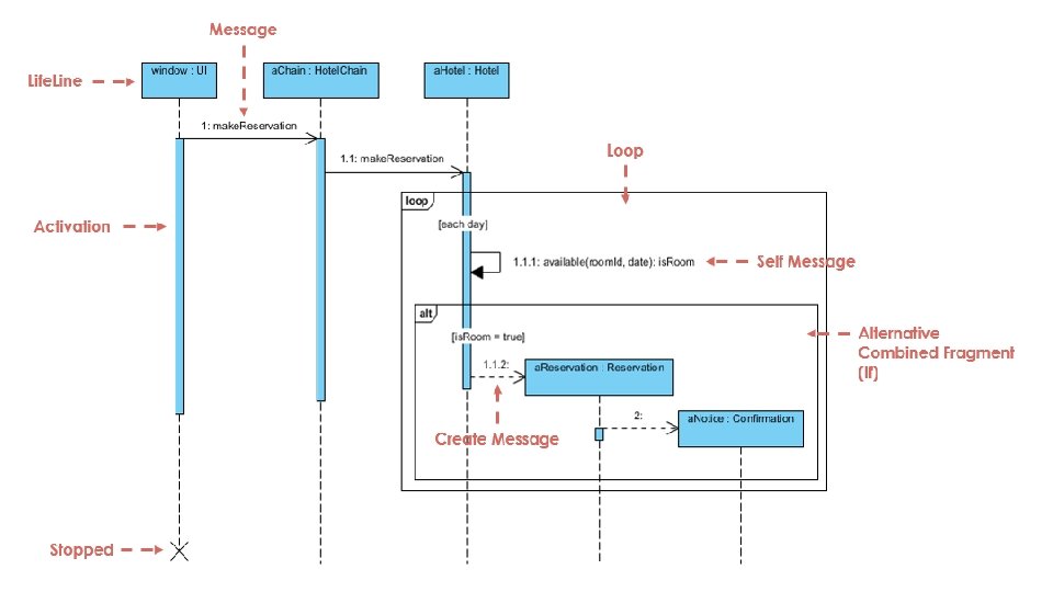
Sequence Diagram Example: Hotel System • Sequence Diagram is an interaction diagram that details how operations are carried out -- what messages are sent and when. Sequence diagrams are organized according to time. The time progresses as you go down the page. The objects involved in the operation are listed from left to right according to when they take part in the message sequence. • Below is a sequence diagram for making a hotel reservation. The object initiating the sequence of messages is a Reservation window.
• Note That: Class and object diagrams are static model views. Interaction diagrams are dynamic. They describe how objects collaborate. • Sequence Diagram Notation • Actor: type of role played by an entity that interacts with the subject (e. g. , by exchanging signals and data) • external to the subject (i. e. , in the sense that an instance of an actor is not a part of the instance of its corresponding subject). • represent roles played by human users, external hardware, or other subjects.
Note that: An actor does not necessarily represent a specific physical entity but merely a particular role of some entity A person may play the role of several different actors and, conversely, a given actor may be played by multiple different person.
Lifeline • A lifeline represents an individual participant in the Interaction.
Activations • A thin rectangle on a lifeline) represents the period during which an element is performing an operation. • The top and the bottom of the rectangle are aligned with the initiation and the completion time respectively
Call Message • A message defines a particular communication between Lifelines of an Interaction. • Call message is a kind of message that represents an invocation of operation of target lifeline.
Return Message • A message defines a particular communication between Lifelines of an Interaction. • Return message is a kind of message that represents the pass of information back to the caller of a corresponded former message.
Self Message • A message defines a particular communication between Lifelines of an Interaction. • Self message is a kind of message that represents the invocation of message of the same lifeline.
Recursive Message • A message defines a particular communication between Lifelines of an Interaction. • Recursive message is a kind of message that represents the invocation of message of the same lifeline. It's target points to an activation on top of the activation where the message was invoked from.
Create Message • A message defines a particular communication between Lifelines of an Interaction. • Create message is a kind of message that represents the instantiation of (target) lifeline.
Destroy Message • A message defines a particular communication between Lifelines of an Interaction. • Destroy message is a kind of message that represents the request of destroying the lifecycle of target lifeline.
Duration Message • A message defines a particular communication between Lifelines of an Interaction. • Duration message shows the distance between two time instants for a message invocation.
Note • A note (comment) gives the ability to attach various remarks to elements. A comment carries no semantic force, but may contain information that is useful to a modeler.
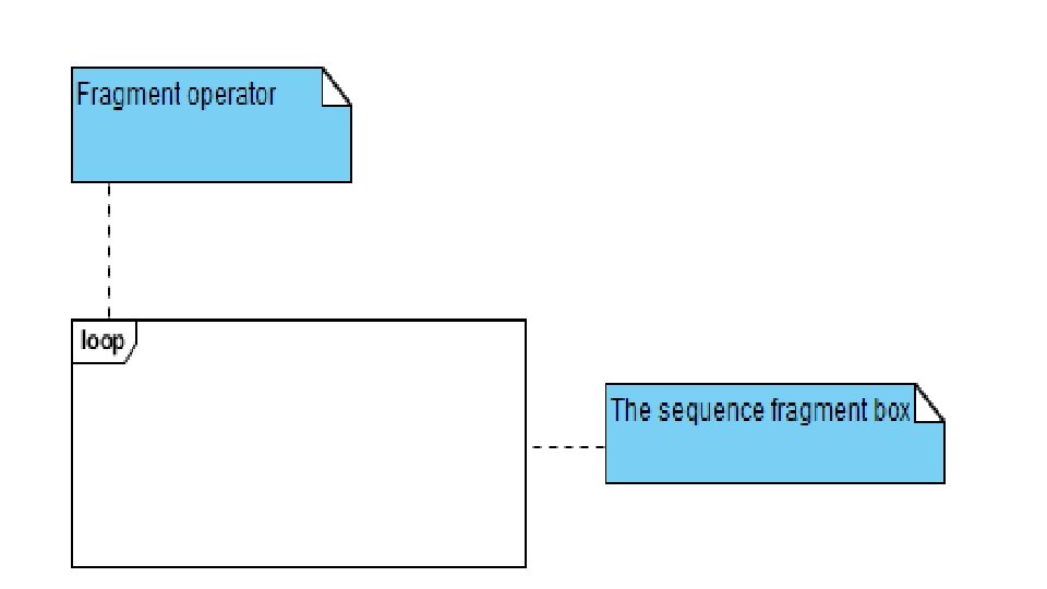
Sequence Fragments • UML 2. 0 introduces sequence (or interaction) fragments. Sequence fragments make it easier to create and maintain accurate sequence diagrams • A sequence fragment is represented as a box, called a combined fragment, which encloses a portion of the interactions within a sequence diagram • The fragment operator (in the top left cornet) indicates the type of fragment • Fragment types: ref, assert, loop, break, alt, opt, neg
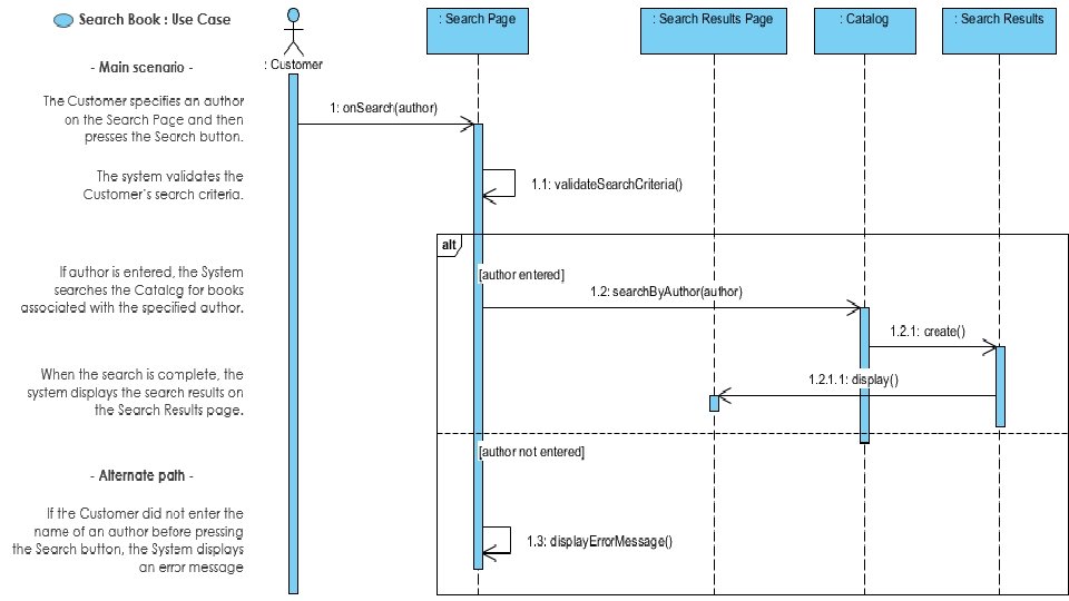
Sequence Diagram for Modeling Use Case Scenarios • User requirements are captured as use cases that are refined into scenarios. A use case is a collection of interactions between external actors and a system. In UML, a use case is: • "the specification of a sequence of actions, including variants, that a system (or entity) can perform, interacting with actors of the system. " • A scenario is one path or flow through a use case that describes a sequence of events that occurs during one particular execution of a system which is often represented by a sequence diagram. • PS: THIS NEEDS MORE READING, HOPE NO ONE IS CONFUSED
Sequence Diagram - Model before Code • Sequence diagrams can be somewhat close to the code level, so why not just code up that algorithm rather than drawing it as a sequence diagram? • A good sequence diagram is still a bit above the level of the real code • Sequence diagrams are language neutral • Non-coders can do sequence diagrams • Easier to do sequence diagrams as a team