What is memory Memory is used to store


 This is memory whose contents are not lost if the")
 For most PCs, main memory is stored using RAM chips.")


 are constructed in")


 l A DVD uses – – – l the same")

 this points to the memory location/address of the")


 for fetch part of the cycle. l Short hand notation")


/(k+n-1) l If n=50 (50 instructions in a sequence) l S=")
 This carries out arithmetic operations such as")


")


- Slides: 61
What is memory? Memory is used to store information within a computer, either programs or data. Programs and data cannot be used directly from a disk or CD, but must first be moved in memory: l. RAM and ROM l. Cache l. Memory Hierarchies
l l l Each part of memory has a separate memory location, which can be referred to using a memory address. Size of memory is measured in bytes (or multiples such as kilobytes (KB) or megabytes (MB)). The two main types of memory (RAM and ROM) act as if they were two parts of a continuous list of memory addresses.
Read only Memory (ROM) This is memory whose contents are not lost if the machine is switched off. This is also called non-volatile memory. There are variations on this basic idea. l. Programmable ROM: Programmed after manufacture. Once they are programmed, the basic ROM and PROM cannot be changed.
Random Access Memory (RAM) For most PCs, main memory is stored using RAM chips. These are volatile so switch the machine off and the contents in this form of memory are lost. There are 3 basic types of RAM – Dynamic RAM (DRAM) – Static RAM (SRAM) – Non-volatile RAM (NVRAM)
Cache is faster type of memory than is found in main memory. In other words, it takes less time to access something in cache than in main memory. It ‘sits’ between external memory (main memory) and the processor. Runs at the speeds close to that of the processor and has two main types.
l L 1 which stores instructions going to the processor. Often split into two L 1 cache for instructions and L 1 cache for data. l L 2 which is used buffer data between L 1 cache and main memory, sometimes called unified cache.
Principle of locality l l l The nature of programs and structure of data often means that requests to memory are not random, but localised. Programs tend to reuse data and instructions that have been recently used – temporal locality. Instructions and data referenced closed together in time, or often close together physically in memoryspatial locality.
When data is transferred between main memory and the processor, a copy of the data is saved to cache. l. When the processor needs more data, the addresses are checked to see if the data is already in the cache, if it there is no need to transfer the data from main memory which is slower. l. This is a cache hit and the data is taken directly from the cache. l. If the data is not, in the cache, this is known as a cache miss and a memory transfer is performed.
The ability to store more data in a cache will makes the computer faster, so bigger caches are an advantage. However, cost is a limiting factor as this type of memory is more expensive than main memory.
Virtual Memory In its simplest form: lvirtual memory uses a portion of the hard disk as extra memory. l. This is slower than using RAM. l. Virtual memory is useful when the programs and data in use are bigger than main memory’s capacity. We will meet this in more detail later in the module.
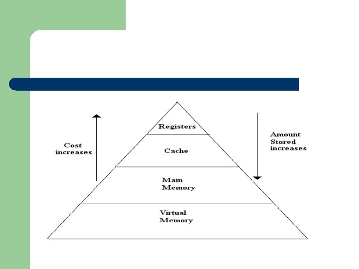
Memory Hierarchies Memory systems (a collection of various forms of memory) are constructed in a hierarchy. As a rule of thumb the faster the memory the higher the cost in terms of price, making it very expensive to make all the memory out of the fastest memory devices. Slower technologies are less expensive, making it more practical to make larger memories out of these devices.
l. At the top of hierarchy is a type of memory called registers these are fast, – – – l. The – – – but only provide a very limited and temporary storage usually part of the processor. expensive. next level is cache memory which is expensive fast access time (time taken to access the data stored). The amount that can be stored (capacity) in cache is greater than is stored in the registers, but is slower than the registers to access.
The next level is main memory. This has a greater capacity than cache, but is slower than cache to access. At the bottom of the hierarchy is virtual memory. This has potentially the greatest capacity, but is the slowest to access.
So the higher level in the hierarchy a device the less that can be stored in but the quicker it is to access. The goal of a memory hierarchy is to keep the data that is accessed most high up the hierarchy, so it can be accessed quickly, the least used at the bottom of the hierarchy.
Magnetic l l All magnetic disk storage allows direct access to the data. When data is written to or read from disk, a particular part of the disk can be identified and use by its address. Disk can usually be read from or write on both the top and bottom of the disk.
l A disk address uses sector and track. To access a location on disk: – – the read/write heads have to move to the appropriate track Wait for correct sector to appear under the head. The speed at which the data can be read from or written to the disk is called the seek time and is usually referred to as the average seek time and is measured in milliseconds (ms) and is the time taken to travel to the appropriate track.
l The data on a disk is stored in a binary form as magnetic dots along the tracks, often as one polarity for a 1 and the other polarity for 0. The read/write head (R/W head) detects the polarity, because there are only two polarities, there are only two states. The pattern of pulses produced by the R/W head in relation to the drive timing is translated into data and set to the CPU.
Types of magnetic media l l Floppies Hard disks ZIP drives Tape and JAZ drives
Optical media l Magnetism is not the only way data can be stored, another option is to use optical media where the disk has holes burnt in it by a laser to record the binary code. A hole or pit on the disk reflects less light than the surface of the disk. By detecting the difference in reflected light in relation to the time of the drive, a pattern of pulse is produced and this is translated into data sent to the CPU.
Compact Disks l CDs are optical media storing approximately 650 MB of data, but are slower than a hard disk to access. The head used for reading from a CD has two parts a laser that shines on a small part of the disk and a light sensor to measure the reflected light.
Digital versatile disk (DVD) l A DVD uses – – – l the same basic principle as a CD, the data is packed more densely Smaller and narrower pits it has a larger capacity (4. 7 GB) as compared to a CDs 650 MB, it also has a quicker transfer rate than a CD. Better compression algorithms help to improve the capacity.
Fetch l All programs are stored in memory, and have to be ‘fetched’ from memory before they can be carried out (executed). l Before the CPU can use an instruction, the instruction must be brought to the CPU from the memory.
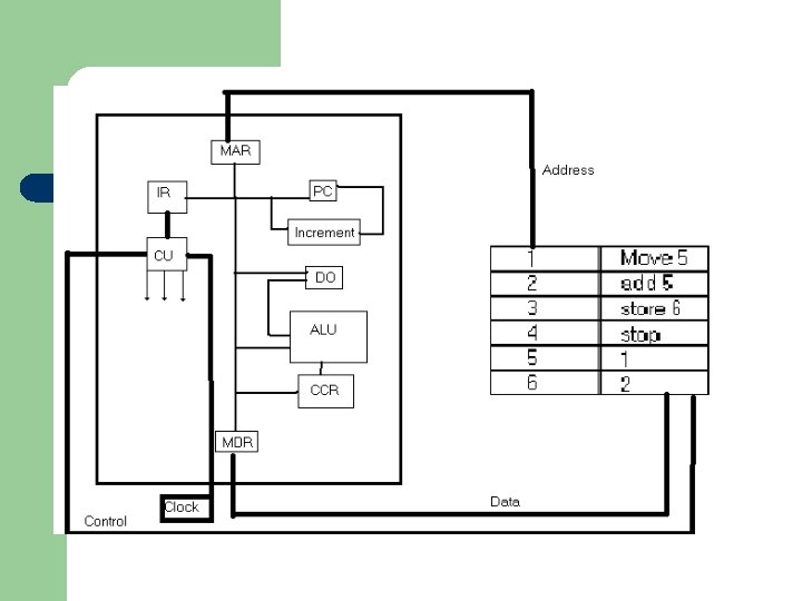
Starting with a program counter (PC) this points to the memory location/address of the next instruction to be executed. Therefore, if the contents of the PC were 5, the next instruction to be executed is stored in memory location 5.
l l The contents of the program counter are copied to the memory address register (MAR). The program counter contents are then incremented to the next instruction. The MAR holds the address of the memory location where in memory the data is to be used is located. Note: The MAR does not just do this in the fetch part. If you taking something out of memory or putting something into memory the address of the memory location has to be there
l The contents of MAR during this part of the cycle contains address of the instruction to be executed, the contents of this memory location are placed into the memory data register (MDR).
l l During this part of the cycle the data that is passed from memory is an instruction. The instruction is moved from the MDR to the instruction register (IR) where it is divided into two fields.
l One field is the operation code often shortened to opcode, which tells the CPU the instruction to carry out. l The second field is the operand field, which contains the address/data (or addresses) of data used by the instruction. Sometimes the operand field is not used.
RTL (Register Transfer Language) for fetch part of the cycle. l Short hand notation for describing register transfers – – – [MAR] [PC]+1 [MDR] [M([MAR])] [IR] [MDR] CU [IR(opcode)]
l The next stage is the decode-execute cycle where the control unit takes the opcode from the instruction register, and generates the control signals to control the various parts of the CPU. The control unit is responsible during the fetch cycle for all the operations to make the fetch happen
l l l Pipelining is a key technique used to make faster CPUs. Processors allow instructions to be executed in stages; stages implemented using separate hardware. Stages connected together forming an instruction pipeline, allowing more than one instruction to be processed at the same time.
Fetch-execute cycle stages fetch 1 decode execute instruction 1 2 instruction 1 3 instruction 1 4 5 6 7 8 write-back instruction 1 instruction 2
Pipelining
Speed up l If a k-stage pipeline executes n instructions using a clock with a cycle time t, without overlapping instructions the total time to execute instructions will be l So if 4 stages are used (k=4), 4 instructions (n=4), and t=1 s, Ts=16 s.
l If instructions are executed in parallel, where kt is the time to fill-up to the point where the first instruction completes and (n-1)t is time taken for the remaining (n-1) instructions at a rate of one per clock cycle.
l Speedup factor, S=Ts/Tp=(nk)/(k+n-1) l If n=50 (50 instructions in a sequence) l S= (50*4)/(4+50 -1)=3. 77 l If n=100 S=3. 88
l l Arithmetic and Logic Unit (ALU) This carries out arithmetic operations such as adding or subtracting, and logical operations. Control Unit (CU) This controls the execution of instructions. Input and Output Ports (I/O) Communicates with the outside world, either reading in data or sending data out. Clock This produces regular pulses which controls the rate at which instructions are carried out.
Registers l l A register is a small storage unit which holds a single piece of data. Program status word: This register contains information about the result of operations such as if the result is negative or zero.
l Initially these processors were designed with a smaller number of instructions around 50, so name Reduced Instruction set computer (RISC) in contrast with Complex instruction set Computer (CISC) (VAX, etc). Later RISC processors may have larger set of instructions.
Why has RISC not replaced CISC completely? l l l Backward compatibility, billons pounds (or dollars) have been invested in software for the Intel line Intel employed some of the RISC ideas in the 486 s upwards. It contained a RISC core to execute simplest and most common instructions, while the more complicated instructions in the usual CISC way. So common instructions are generally fast and less common instructions are slow. hybrid approach not a pure RISC design. This allows higher performance but still allowing old software to run unmodified.
ALU l Arithmetic Logic Unit l Carries out all arithmetic operations l Carries out all logic operations, including comparison (>, <. equal to, not equal to, etc) not just ANDs, Ors, etc.
Example AVR instructions l l ldi ldi r 18, 0 xff r 18, 0 b 1111 r 18, 255 These all do the same thing they put the value (load) of 255 into register r 18, as either a hexadecimal, binary, or decimal number. Look up some of these other instructions you used in the practical.
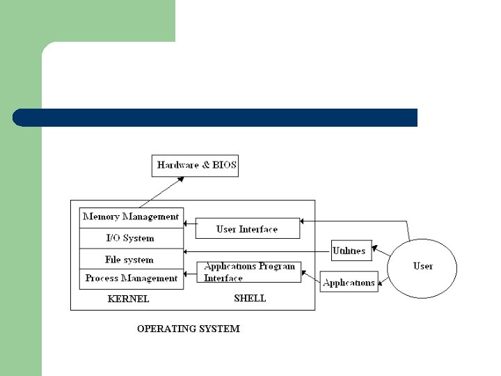
What is an operating system? l A short definition of an operating system: An operating system is a collection of system programs that manage the resources of a computer and control the running of user programs.
l Kernel – – l Central part of the operating system. All hardware requests go through the kernel as system calls Shell – The interfaces for the applications programs and users, with the operating system.
l Process manager deals with – – hardware/software interrupts. Processor errors Scheduling tasks Communication between tasks
l Memory Management – – – Allocate memory Ensures processes (see next week’s lecture) stay memory boundaries Controlling virtual memory
l I/0 System – – Communicates with peripherals and hardware components Co-ordinates i/o systems such as interrupts and direct memory access
l Files system – – – Organises and accesses files Maintains on a multi-user system user file quotas Controls file/record access
l Application Program Interface – – Provides systems services for applications An interface between the applications and the operating system.
l User interface – – – Allows the user access to programs Allows the user to view and change system settings. A consistent interface between the user and the operating system.
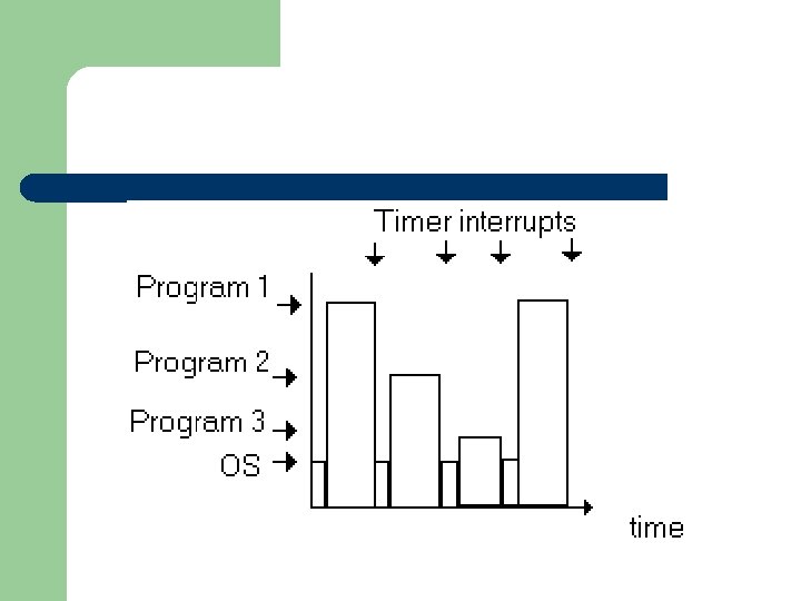
l Most modern operating systems have the ability to execute several programs at once, although there is usually one processor in the system. This is multiprogramming and is made possible by rapidly switching the processor between programs. Interrupting the processor periodically, gives the programs control of the processor for a short period.
l This switching is triggered by a piece of hardware called the interval timer, which generates an interrupt (a time-out interrupt) when the programmed period has elapsed. The interrupt handler, then saves the context of the processor. The context is the contents of registers that may be overwritten by other programs. Control is passed over to the dispatcher/low-level scheduler.
l The dispatcher searches a set of potentially 'runnable' program using a scheduling algorithm to select a suitable program to run next. The context of the processor, which existed when that program last ran, is restored to the registers.
l A process consists of an executable program, the data associated with the program, and it’s execution context. The execution context includes the processor context, but also information such as the process identifier, priority level, and a process state
Process-3 states
l When a user process is in the running state, the processor is executing the program code. If a timer interrupt occurs, the running process is moved into ready state, and another process form the list of processes in the ready state is moved into the running state.
l If a process in the running state requests an operating system service and it must wait for it, then the process is moved into the blocked state.
l A process will remain in the blocked state until the event required has taken place, the process can then be moved back into the ready state. If a process is blocked the operating system is free to reschedule another processor.