WELDING Welding is a process of metal joining


 vs. Alternating current (AC) –")


. • Used for")
, the fluxes")


 Inert gas is")
 Continuous wire Solidified weld metal Uses a consumable electrode")
 Figure : Gas metal arc welding (GMAW).")
 : - Main equipment - torch - electric power source")
 process The heat is produced by an electric arc")
 process GMAW torch nozzle cutaway image : (1) Torch handle,")
 Metal Inert Gas Welding (Gas Metal Arc Welding)")
: • Continuous weld may be produced")
")
")

operations.")
 Tungsten Inert Gas Arc Welding (Gas Tungsten")
: • Weld composition is close")


 § Temperatures in PAW reach")
 transferred (b) non transferred. Figure : Two types of plasma-arc welding")
 PAW is the next step in GTAW. Plasma Arc Welding")
 Transferred arc process produces plasma jet of high energy density")
: Ensures greater arc stability • Requires less operator")
 Adaptation of shielded metal arc welding, to overcome limitations of")


 Uses a continuous consumable electrode, either flux‑cored wire or bare with")
 front")


 1. Electro slag Welding is the welding process in which")
;")
 Uses a continuous, consumable bare wire electrode, with arc")
 n Welding arc is shielded by a granular flux")


 1. The flux containing calcium oxide, calcium fluoride, silica is")
: Very high welding rate; The")

- Slides: 60
WELDING Welding is a process of metal joining by applying heat and sometimes pressure
Classification of welding processes welding Forge or Pressure Welding Fusion or non pressure welding ( Under pressure without additional filler metal ) ( With additional filler metal ) Forge or Pressure welding : - The work piece are heated to plastic state & then work pieces are joined together by applying pressure on them. In this case no filler material is used. Fusion or non- pressure welding : - Here edge of work piece to be joined & filler materia both are heated to a temp. above the melting point of the metal & then allow to solidify
Forge or pressure welding Welding heat created by Furnace Forge or furnace welding Spot seam Electric current Resistance welding projection friction welding flash butt
Fusion or non pressure welding Welding heat created by gas Electric Arc Oxy-acetylene welding chemical reaction Thermit welding Non Consumable electrode plasma arc Shielded metal arc MIG atomic hydrogen electro slag submerged arc Flux cored Carbon arc TIG
Other processes of welding are : Solid State welding : The solid state welding depends upon theory that if two perfectly clean metallic surfaces are placed in an intimate contact , the cohesive force between atoms of the two surfaces is sufficient to hold them together. The various solid state welding process are: Friction Welding Ultrasonic Welding Diffusion Welding Explosive Welding Modern Welding Processes: Electron Beam Welding Laser Beam Welding
Terms used in welding : Weld Pool : - Nature of deposition of the filler material in fusion zone is know as weld pool ( Puddle ) Slag : - molten or fused flux is called as slag Flux : - mixture of Borax and sodium carbonate is coated to electrode for shielding purpose. Electric arc : An electric arc is a discharge of electric current across a gap in a circuit. To initiate the arc in Arc Welding electrode is brought into contact with work and then quickly separated from it by a short distance Electric arc between the electrode and work piece closes the electric circuit. The arc temperature may reach 10000°F (5500°C), which is sufficient for fusion the work piece edges and joining them.
Arc Welding Figure : Basic configuration of an arc welding process. A pool of molten metal is formed near electrode tip, and as electrode is moved along joint, molten weld pool solidifies in its wake
Two Basic Types of AW Electrodes • • Consumable – consumed during welding process – Source of filler metal in arc welding Nonconsumable – not consumed during welding process – Filler metal must be added separately Consumable Electrodes : Forms of consumable electrodes : Welding rods are 9 to 18 inches and 3/8 inch or less in diameter and must be changed frequently Weld wire can be continuously fed from spools with long lengths of wire, avoiding frequent interruptions In both rod and wire forms, electrode is consumed by arc and added to weld joint as filler metal Non consumable Electrodes : Made of tungsten which resists melting Gradually depleted during welding (vaporization is principal mechanism) Any filler metal must be supplied by a separate wire fed into weld pool
Terms used in welding : Shielding is one of the unique requirements of arc welding. Welds will have better chemical and physical properties if the air can be kept away from the weld puddle. Such gases as oxygen, hydrogen, and nitrogen, along with water vapor (moisture) all tend to reduce the quality of the weld. Dirt, dust, and metal oxides (contaminants) also reduce the weld quality. Shielding of the arc preserves the integrity of the weld joint. Shielding is provided either by : • Decomposition of the electrode covering, known as flux – Flux coated electrode • A gas (or gas mixture) which may be inert. § e. g. , argon, helium, CO 2 Shielding
Terms used in welding : Functions of flux Protects the weld from oxidizing with atmosphere by producing a shield of gas around the arc and weld pool Provide the slag which floats at the top of molten metal so as to protect the weld from rapid cooling and to protect weld from atmosphere. The slag is then brushed off after weld gets cooled. Various Flux Application Methods Pouring granular flux onto welding operation Stick electrode coated with flux material that melts during welding to cover operation ( flux coated electrodes ) Tubular electrodes in which flux is contained in the core and released as electrode is consumed
Power Source in Arc Welding • Direct current (DC) vs. Alternating current (AC) – AC machines less expensive to purchase and operate, but generally restricted to ferrous metals – DC equipment can be used on all metals and is generally noted for better arc control
Polarity in Arc Welding • Polarity is defined as the type of potential given to the workpiece or electrode. – In case of a A. C. power source , positive and negative terminal are not fixed. i. e. the terminal which is positive during one half cycle , becomes negative in another half. – In case of a D. C. power source , positive and negative terminals are fixed. So polarity principle mainly applicable in case of D. C. power source. – Polarity is of two types : – 1. Straight Polarity : Electrode is having negative terminal while workpiece is connected to the positive terminal of D. C. power supply – 2. Reverse Polarity : Electrode is connected to positive terminal , whereas work piece is connected to the negative terminal of the D. C. power source. – About 2/3 of the total heat produced during welding is generated at positive terminal , while the rest of the total heat is generated at negative terminal. – So if our job is thick , means we want more heat on work piece, so we connect work piece to the positive terminal , hence we adopt straight polarity. Similarly , if the job is thin, means , we want less heat on job , so we connect work piece to the negative terminal , hence we adopt reverse polarity – If our electrode is non-consumable, means we want less heat on electrode so we connect electrode to the negative terminal. i. e. use of straight polarity.
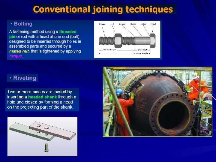
Shielded Metal Arc Welding – Consumable electrode coated with chemicals that provide flux and shielding – The filler metal (here the consumable electrode) is usually very close in composition to the metal being welded.
Shielded Metal Arc Welding Figure : Shielded metal arc welding (SMAW). • Used for steels, stainless steels, cast irons, and certain nonferrous alloys • Not used or rarely used for aluminum and its alloys, copper alloys, and titanium
INERT GAS WELDING In conventional arc welding ( metal arc welding ), the fluxes are used to shield atmosphere around the molten metal and arc. In inert gas ( Arc ) welding, separate inert gas such as argon, helium, carbon dioxide are used for surrounding the electric arc and molten metal from the metal. Thus inert gas serves as a shielding gas which displaces the oxygen and nitrogen from the air surrounding the arc and molten metal. Thus it provides protective shield around arc and molten metal. Thus it eliminates formation of metal oxides and nitrides which lower weld metal ductility and toughness.
INERT GAS WELDING Inert gas welding is of following types 1. Gas tungsten arc welding (GTAW) or Tungsten inert gas ( TIG ) 2. Gas metal arc welding ( GMAW ) or Metal inert gas ( MIG )
INERT GAS WELDING Similarities between TIG and MIG 1. No fluxes are used to shield the atmosphere around molten metal 2. Instead of that , both are using separate inert gas ( Argon, helium, Carbon dioxide ) for shielding purpose 3. Differences between TIG and MIG TIG 1. Arc is stuck between a non consumable tungsten electrode and work piece to be welded. 2. Filler material is added from a hand held filler rod or wire of the same composition as the work piece MIG 1. Arc is struck between consumable electrode( which serves as a filler material ) and work piece to be welded. 2. The electrode / filler is a wire fed from a reel continuously to the welding zone. Consumable electrode is having the same composition as work piece material
Uses a consumable electrode (filler wire made of the base metal) Inert gas is typically Argon
Gas Metal Arc Welding (MIG) Continuous wire Solidified weld metal Uses a consumable electrode (filler wire made of the base metal) Inert gas is typically Argon
Gas Metal Arc Welding ( TIG ) Figure : Gas metal arc welding (GMAW).
GMAW ( MIG ) : - Main equipment - torch - electric power source - shielding gas source - wire spool with wire drive control Equipment required for the GMAW
The GMAW ( MIG ) process The heat is produced by an electric arc between the continuously fed metal electrode and the base metal. Both the base metal and the filler are melt. The weld area is protected by inert shield gases. Weldable metals: -steel carbon - steel low-allow - steel stainless - aluminum - copper and its allows - nickel and its allows - magnesium - reactive metal (titanium, zirconium, tantalum) Characteristics of the weld joint by GMAW
GMAW ( MIG ) process GMAW torch nozzle cutaway image : (1) Torch handle, (2) Molded phenolic dielectric (shown in white) and threaded metal nut insert (yellow), (3) Shielding gas nozzle, (4) Contact tube, (5) Nozzle output face
Metal Inert Gas Welding (MIG, GMAW) Metal Inert Gas Welding (Gas Metal Arc Welding) is the arc welding process, in which the weld is shielded by an external gas (argon, helium, CO 2, argon + oxygene or other gas mixtures). Consumable electrode wire, having chemical composition similar to that of the parent material, is continuously fed from a spool to the arc zone. The arc heats and melts both the work pieces edges and the electrode wire. The fused electrode material is supplied to the surfaces of the work pieces, fills the weld pool and forms joint. Due to automatic feeding of the filling wire (electrode) the process is referred to as a semi-automatic. The operator controls only the torch positioning and speed.
Advantages of Metal Inert Gas Welding (MIG, GMAW): • Continuous weld may be produced (no interruptions); • High level of operators skill is not required; • Slag removal is not required (no slag); • High welding speed and can be easily automated Disadvantages of Metal Inert Gas Welding (MIG, GMAW): • Expensive and non-portable equipment is required; • Outdoor application are limited because of effect of wind, dispersing the shielding gas. GMAW Advantages over SMAW • • • Better arc time because of continuous wire electrode – Sticks must be periodically changed in SMAW Better use of electrode filler metal than SMAW – End of stick cannot be used in SMAW Higher deposition rates Eliminates problem of slag removal Can be readily automated
Gas Tungsten Arc Welding ( TIG )
Gas Tungsten Arc Welding ( TIG )
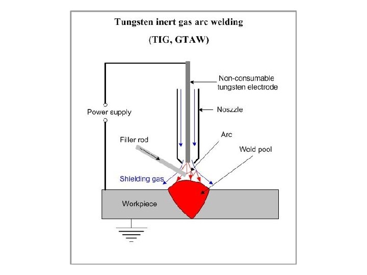
Gas Tungsten-Arc Welding Figure : The gas tungsten-arc welding process, formerly known as TIG (for tungsten inert gas) welding.
Gas Tungsten-Arc Welding Figure : Equipment for gas tungsten-arc welding ( TIG )operations.
Tungsten Inert Gas Arc Welding (TIG, GTAW) Tungsten Inert Gas Arc Welding (Gas Tungsten Arc Welding) is the welding process, in which heat is generated by an electric arc struck between a tungsten non-consumable electrode and the work piece. The weld pool is shielded by an inert gas (argon, helium, nitrogen) protecting the molten metal from atmospheric contamination. The heat produced by the arc melts the work pieces edges and joins them. Filler rod may be used, if required. Tungsten Inert Gas Arc Welding produces a high quality weld of most of metals. Flux is not used in the process.
Advantages of Tungsten Inert Gas Arc Welding (TIG, GTAW): • Weld composition is close to that of the parent metal; • High quality weld structure • Slag removal is not required (no slag); • Thermal distortions of work pieces are minimal due to concentration of heat in small zone. • Flux is not used; therefore, finished welds do not require cleaning of corrosive residue. Disadvantages of Tungsten Inert Gas Arc Welding (TIG, GTAW): • Low welding rate; • Relatively expensive • Requres high level of operators skill
Plasma Arc Welding
Plasma Arc Welding Figure : Plasma arc welding (PAW) § Temperatures in PAW reach 28, 000 C (50, 000 F), due to constriction of arc, producing a plasma jet of small diameter and very high energy density
Plasma-Arc Welding (a) transferred (b) non transferred. Figure : Two types of plasma-arc welding processes: (a) transferred, (b) non transferred. Deep and narrow welds can be made by this process at high welding speeds.
Plasma Arc Welding (PAW) PAW is the next step in GTAW. Plasma Arc Welding is a welding process utilizing heat generated by a constricted arc (plasma jet ) struck between a tungsten non-consumable electrode and either the work piece (transferred arc process) or water cooled constricting nozzle (nontransferred arc process). Plasma is a high temperature ionised gas which is a mixture of positive ions, electrons and neutral gas molecules. The gas is forced past an electric arc thtough a constricted openining( orifice ) at the end of water cooled nozzle. Due to this gas gets heated and becomes ionised which is a plasma. As the arc is constricted, proportion of ionised gas increases and plasma jet is created. This results in a more concentrated heat source at a higher temperature that greatly increases the heat transfer efficiency, allowing for faster travel speeds. This plasma jet will take a narrow, columnar shape that make it ideal for welding This process uses two inert gases , one forms the plasma and second shield the arc weld metal. Filler rod may or may not be supplied.
Plasma Arc Welding (PAW) Transferred arc process produces plasma jet of high energy density and may be used for high speed welding and cutting of Ceramics, steels, Aluminum alloys, Copper alloys, Titanium alloys, Nickel alloys. Arc is struck between tungsten non-consumable electrode and work piece Non-transferred arc process produces plasma of relatively low energy density. It is used for welding of various metals and for plasma spraying (coating). Arc is struck between non consumable electrode and water cooled constricted nozzle. Since the work piece in nontransferred plasma arc welding is not a part of elctric circuit, the plasma arc torch may move from one work piece to other
Advantages of Plasma Arc Welding (PAW): Ensures greater arc stability • Requires less operator skill due to good tolerance of arc to misalignments; • High welding rate; • High penetrating capability (keyhole effect); Disadvantages of Plasma Arc Welding (PAW): • Expensive equipment; High distortions and wide welds as a result of high heat input.
Flux‑Cored Arc Welding (FCAW) Adaptation of shielded metal arc welding, to overcome limitations of stick electrodes • Electrode is a continuous consumable tubing (in coils) containing flux and other ingredients (e. g. , alloying elements) in its core • Two versions: – Self‑shielded FCAW - core includes compounds that produce shielding gases – Gas‑shielded FCAW - uses externally applied shielding gases
Flux-Cored Arc Welding Figure : Flux‑cored arc welding. Presence or absence of externally supplied shielding gas distinguishes the two types: (1) self‑shielded, in which core provides ingredients for shielding, and (2) gas‑shielded, which uses external shielding gases.
Flux-Cored Arc-Welding Figure : Schematic illustration of the flux-cored arc-welding process. This operation is similar to gas metal-arc welding
Electrogas Welding (EGW) Uses a continuous consumable electrode, either flux‑cored wire or bare with externally supplied shielding gases, and molding shoes to contain molten metal • When flux‑cored electrode wire is used and no external gases are supplied, then special case of self‑shielded FCAW • When a bare electrode wire used with shielding gases from external source, then special case of GMAW
Electro gas Welding Figure : Electro gas welding using flux‑cored electrode wire: (a) front view with molding shoe removed for clarity, and (b) side view showing molding shoes on both sides.
Direction of welding During process slag should get solidified It is continuously maintained in molten state through out the operation due to Heat produced by continuously electric current.
Equipment for Electro slag Welding
Electro slag Welding (ESW) 1. Electro slag Welding is the welding process in which the heat is generated by an electric current passing between the consumable electrode (filler metal ) and the work piece through a molten slag, which covers the weld surface. 2. In this process, plates to be welded are put in vertical position with certain gap. The consumable wire electrode is kept in this gap. Prior to welding, the gap between the two work pieces is filled with a welding flux. 3. Electro slag Welding is initiated by an arc between the electrode and the work piece (or starting plate). Heat, generated by the arc, melts the fluxing powder and forms molten slag. The slag, having low electric conductivity, is maintained in liquid state due to heat produced by the electric current. 4. The slag reaches a temperature of about 1950°C inside and outside. Temperature of about 1650°C. This temperature is sufficient to melt Both consumable electrode and work piece edges. Electro slag Welding is used mainly for steels.
Advantages of Electroslag Welding: High deposition rate - up to 45 lbs/h (20 kg/h); Low slag consumption (about 5% of the deposited metal weight); Low distortion; Unlimited thickness of work piece. Disadvantages of Electroslag welding: Coarse grain structure of the weld; Low toughness of the weld; Only vertical position is possible.
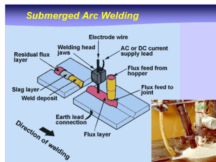
Submerged Arc Welding ( SAW) Uses a continuous, consumable bare wire electrode, with arc shielding provided by a cover of granular flux Electrode wire is fed automatically from a coil Flux introduced into joint slightly ahead of arc by gravity from a hopper Completely submerges operation, preventing sparks, spatter, and radiation
Submerged Arc Welding ( SAW) n Welding arc is shielded by a granular flux consisting of lime, silica, manganese oxide, calcium fluoride n Flux: insulates weld area, allows deep thermal penetration n Prevents spatter and spark over molten metal n Shielded glass etc is unnecessary n 300 – 2000 Amp n Speed 5 m/min n Thick plate welding – 4 to 10 times more weld material than SMAW. n Carbon, allow, stainless steel etc
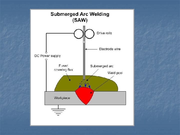
Submerged Arc Welding Figure : Submerged arc welding. Unfused flux is recovered and reused
Submerged Arc Welding Unfused flux is recovered and reused
Submerged Arc Welding
Submerged Arc Welding (SAW) 1. The flux containing calcium oxide, calcium fluoride, silica is crushed to form a coarse powder ( granulated flux powder ). This powder is then spread over the point ( weld) to be formed. 2. A consumable electrode is fed into this flux. Since the electrode is submerged into the flux, the arc is invisible. 3. When power supply is on, arc is formed , which is submerged under the layer of the powder. The intense heat of the arc produces a pool of molten metal in the joint ( weld). At this time, a portion of flux melts which protect the liquid weld pool from surrounding whereas rest of the flux ( which has not melted by the arc heat ) protects( shields) the arc ( from the surrounding ) 4. This molten flux acts as a cleaner , absorbing impurities from the molten metal and producing slag, which floats on the top of molten metal. This slag solidifies with the molten metal and can be easily brushed off.
Submerged Arc Welding Advantages of Submerged Arc Welding (SAW): Very high welding rate; The process is suitable for automation; High quality weld structure. Disadvantages of Submerged Arc Welding (SAW): Weld may contain slag inclusions; Limited applications of the process - mostly for welding horizontally located plates.
SAW Applications and Products n n n Steel fabrication of structural shapes (e. g. , I‑beams) Seams for large diameter pipes, tanks, and pressure vessels Welded components for heavy machinery Most steels (except hi C steel) Not good for nonferrous metals