Welding Definition It is the process of joining


 Arc welding � Carbon arc � Metal inert gas")
 Resistance Welding � Butt � Spot � Seam � Projection � Percussion (iv)Solid")


 and acetylene ( red colour)gas cylinders � Hose")


 is mixed with oxygen(O 2) in")


")


 A group of fusion welding processes that use a combination of")


 � In EBW process, the heat is generated when the")


 Fusion welding process in which coalescence is achieved by energy")


 Desired profile for single V-groove weld joint, (b)")


- Slides: 61
Welding Definition: It is the process of joining two similar or dissimilar metals with the application of heat and with or without the application of pressure. § Welding is used for making permanent joints. § Flux is added to remove impurities and protect the weld from oxidation. Applications It is used in the manufacture of automobile bodies, aircraft frames, railway wagons, machine frames, structural works, tanks, furniture, boilers, general repair work and ship building.
Advantages 1. Process can used for repair work 2. Strength is good 3. Welded joints have high corrosion resistant 4. Different types of joints are possible 5. It is a cost effective and economical process Disadvantages 1. Welding produces harmful radiations 2. It may produce internal stresses, distortion in the weld region 3. Edge preparation is required before welding 4. This process requires skilled operator
Classification of welding processes (i) Arc welding � Carbon arc � Metal inert gas (MIG) � Tungsten inert gas (TIG) � Plasma arc � Submerged arc � Electro-slag (ii) Gas Welding � Oxy-acetylene � Air-acetylene � Oxy-hydrogen
(iii) Resistance Welding � Butt � Spot � Seam � Projection � Percussion (iv)Solid State Welding � Friction � Ultrasonic � Diffusion � Explosive (v)Newer Welding � Electron-beam � Laser
Gas Welding § In this process heat for melting is supplied by combustion of a fuel gas with oxygen. § The fuel gas can be acetylene, hydrogen, propane or butane. § The molten metal from the edges of metal, flows and solidifies together in the weld and a continuous joint is obtained. § A filler metal may be added when the metal is flowing to fill the cavity
Gas welding equipments
� Gas cylinders- oxygen( black colour) and acetylene ( red colour)gas cylinders � Hose pipes � Pressure regulators � Welding torch or blow pipe with needles valves
Oxy acetylene gas welding � This is used for welding almost all metals because it produces comparatively higher temperatures � also an inert gas envelope consisting of CO 2 and H 2 O is formed around the weld which prevents liquid metal from oxidation. � The temperatures obtained are of the order of 3200 o. C -3500 o. C. � Acetylene (C 2 H 2)
Diagram
� In this process, acetylene(C 2 H 2) is mixed with oxygen(O 2) in correct proportions in the welding torch and ignited. � The flame created at the tip of the torch is sufficiently hot to melt and join the parent metal. � The oxy-acetylene flame reaches a temperature of about 3300°C and thus can melt most of the ferrous and non-ferrous metals in common use. � A filler metal rod or welding rod is generally added to the molten metal to build up the seam slightly, for greater strength.
Advantages 1. It can be used for all joints and suitable for all sides and positions 2. Flame can be easily controlled 3. It is suitable for thin sheets 4. Equipment is portable Disadvantages 1. Method is slower than arc welding 2. Distortion of w/p is more than arc welding
Types of Welding Flames � In oxy-acetylene welding, flame is the most important means to control the welding joint and the welding process. � The correct type of flame is essential for the production of satisfactory welds. � The flame must be of the proper size, shape and condition in order to operate with maximum efficiency. � There are three basic types of oxy-acetylene flames 1. Neutral flame (Acetylene and oxygen in equal proportions) 2. Carburizing flame or Reducing flame (excess of acetylene). 3. Oxidizing flame (excess of oxygen).
� The gas welding flames are shown in Fig
Neutral Flame �A neutral flame results when approximately equal volumes of oxygen and acetylene are mixed in the welding torch and burnt at the torch tip. � The temperature is about 3260°C. � The inner cone is light blue in colour. � It is surrounded by an outer flame envelope � This envelope is Usually a much darker blue than the inner cone. � The neutral flame is commonly used for the welding of mild steel, stainless steel, cast Iron, copper, and aluminium.
Carburizing or Reducing flame ► The carburizing flame consist of three different sections called inner cone, intermediate feather and outer ► This ► The flames occurs because of excess of acetylene gas. outer flame envelope is longer than that of the neutral flame and is usually much brighter in colour. ►A carburizing flame has an approximate temperature of 3038°C. ►A carburizing-flame is used in the welding of lead and for carburizing (surface hardening) purpose
Oxidizing flame � The oxidizing flame has an excess of oxygen over the acetylene. � An oxidizing flame can be recognized by the small cone, which is shorter, much bluer in colour and more pointed than that of the neutral flame. The outer flame envelope is much shorter � It is the hottest flame (temperature as high as 3700°C) � But the excess oxygen especially at high temperatures tends to combine with many metals to form hard, brittle, low strength oxides. � So surrounding area to have a dirty appearance. For these reasons, an oxidizing flame is of limited use in welding. � It is not used in the welding of steel. � A slightly oxidizing flame is helpful when welding (i) Copper-base metals (ii) Zinc-base metals and (iii) A few types of ferrous metals
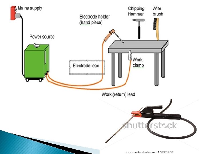
Arc Welding � In these methods heat is generated by an electric current � In theses processes w/p is connected one terminal of power supply and metal electrode is connected to other terminal � An arc is generated about 36000 C temp.
Diagram (welding equipments)
Carbon arc welding � Its is recent type of arc welding process � Electrode is of Carbon material � These are soft and cannot take high current � These electrode consumes slowly, required separate filler rod. � The arc is obtained between carbon electrode and w/p � Generally � Better � It DC power supply is used control on heat input is possible in this method is not suitable for vertical welding positions.
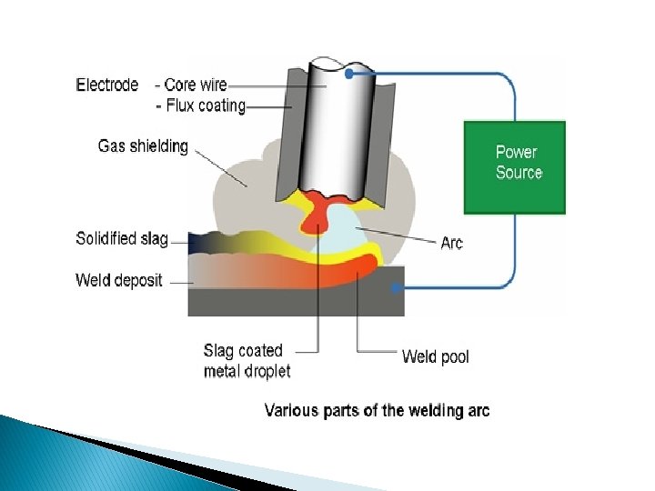
Shielded Metal Arc Welding Working: Its an arc welding process, where the joint welded by heating the w/p with an electric arc set up between the flux coated electrode and w/p
‣ The flux around the electrode gives the stability and protection to weld metal �A high amount of heat is produced between electrode and w/p � The electrode is coated with flux. � The electrode melts itself and serves as filler metal � Molten � The metal transfer from electrode to the job. flux surrounded also melts and makes protective shield over the weld metal
Advantages: � Among all arc welding processes, this one is most simple process � The welding equipments are portable and less costly � Different metals and alloys can be welded � It can be used to any position Limitations: � The process is somewhat slower than MIG or TIG welding � Manually applied, therefore high labour cost � Skilled worker is required
Applications � All popular metals and their alloys � Ship buildings � Joining of pipes � Aircraft � Automobiles � Boilers industry
Gas shielded arc welding � Instead of flux when an inert gas, like argon is used as shield, the method is known as gas shielded arc welding � Mainly two methods comes under this category 1. Tungsten inert gas welding (TIG) 2. Metal inert gas welding (MIG)
TIG Welding §It is also called as gas tungsten arc welding §In this process inert gas is used to keep impurities away from the metal surface
� It uses a non-consumable tungsten electrode and an inert gas for arc shielding � The operation consist of an electric arc struck between the electrode and the w/p � The tungsten electrode does not melt during welding �A filler material can be added separately � In this process the argon gas is used for shielding
Advantages � No flux is required so slag free operation � Different metals can be joined together � No cleaning is required separately � High quality welding Disadvantages � The shielding gas and equipment cost is high � Comparatively slow process Applications � Mostly used for aluminium, magnesium and stainless steel � Used for thin sections up to 7 mm thickness
MIG Welding This process is also known as Gas Metal Arc Welding
� In this process the consumable wire electrode is used � Welding is produced by heating the w/p with an electric arc generated between a continuously fed consumable metal electrode and w/p � The process does not use flux but shielding gas is supplied with electrode � The consumable electrode is in the form of wire reel which is fed at constant rate from the feeding rollers (spool) � The welding torch is connected to the gas cylinder � The gases used for this process are argon, helium, nitrogen, carbon dioxide etc
Advantages � No flux is required so slag free operation � Continuous feeding of electrode makes process faster � This process does not require high degree of operator skill � Welding of thicker sheets are possible Limitations � Process is comparatively complicated � The set up is complex � Equipments are non portable Applications � All commercial metals like Al, Ni and their alloys etc can be welded
comparison Sr. No. TIG MIG 1 It uses non consumable type electrode It uses consumable wire type electrode 2 Electrodes are made of tungsten or its alloys Metal wire electrode of desired composition 3 Electrode only generate an arc and does not melt Electrode generate an arc and melt itself 4 Widely used for thin plates Above 4 mm thick plates can be welded 5 Used for joining dissimilar metals Used for joining similar metals 6 It is slow process but produces smooth weld It is faster process 7 Applications: Mostly used for Al , Mg, stainless steel Applications: Mostly all commercial metals
Plasma Arc Welding What is plasma? � It is fourth state of matter. � When gas(nitrogen, hydrogen etc) is heated up to 140000 C – 280000 C then it is ionized (electrons separated) and it becomes plasma Special form of GTAW in which a constricted plasma arc is directed at weld area � Tungsten electrode is contained in a nozzle that focuses a high velocity stream of inert gas (argon) into arc region to form a high velocity, intensely hot plasma arc stream � Temperatures in PAW reach 28, 000 C (50, 000 F), due to constriction of arc, producing a plasma jet of small diameter and very high energy density
Fig. Shows Plasma Arc Welding
Advantages: � Good arc stability and excellent weld quality � Better � High � Can control than other AW processes travel speeds be used to weld almost any metals Disadvantages: � High equipment cost � Larger � Tends torch size than other AW processes to restrict access in some joints
Resistance Welding (RW) A group of fusion welding processes that use a combination of heat and pressure to accomplish welding process � Heat generated by electrical resistance to current flow at junction to be welded � Principal RW process is resistance spot welding (RSW)
� Resistance welding, showing components in spot welding, the main process in the RW group
Spot Welding � In this process overlapping sheets are joined by local fusion at one or more spots, by the concentration of current flowing between two electrodes. � This is the most widely used resistance welding process.
�A typical resistance spot welding machine is shown in Fig. Construction • It essentially consists of two electrodes out of which one is fixed. • The other electrode is fixed to a rocker arm (to provide mechanical advantage) for transmitting the mechanical force from a pneumatic cylinder. • This is the simplest type of arrangement.
� In spot welding, a satisfactory weld is obtained when a proper current density is maintained. � The current density depends on the contact area between the electrode and the work-piece Working � The squeeze time is the time required for the electrodes to align and clamp the two work-pieces together under them and provide the necessary electrical contact. � The weld time is the time of the current flow through the workpieces till they are heated to the melting temperature. � The hold time is the time when the pressure is to be maintained on the molten metal without the electric current. During this time, the pieces are expected to be forged welded. � The off time is time during which, the pressure on the electrode is taken off so that the plates can be positioned for the next spot.
Spot welding electrodes are made of materials which have � Higher electrical and thermal resistivity's, and Sufficient strength to withstand high pressure at elevated temperatures. � Copper base alloys such as copper beryllium and copper tungsten are commonly used materials for spot welding electrodes.
Seam Welding � It � is a continuous type of spot welding process where as spot welds overlap each other to the desired extent. � In this process coalescence at the surfaces is produced by the heat obtained from the circular electrodes � Resistance to electric current (flow) through the work pieces held together under pressure � The resulting weld is a series of overlapping resistance-spots welds made progressively along a joint.
� The seam welding is similar to spot welding � Except that circular rolling electrodes are used to produce a continuous air-tight seam of overlapping welds.
Applications 1. 2. 3. It is used for making leak proof joints in fuel tanks of automobiles. Except for copper and high copper alloys, most other metals can be seam welded. It is also used for making flange welds for use in watertight tanks.
Projection Welding � This process is a resistance welding process in which two or more than two spot welds are made simultaneously. � In this process raised portions or projections of the w/p on predetermined locations on one of the work piece welded. � These � The projections act to localize the heat of the welding circuit pieces to be welded are held in position under pressure being maintained by electrodes. � The projected contact spot for welding should be approximately equal to the weld metal thickness
� The welding of a nut on the automotive chassis is an example of projection welding.
Advantages: � No filler metal required � High production rates possible � Lower operator skill level than for arc welding � Good repeatability and reliability Disadvantages: � High initial equipment cost � Limited to lap joints for most RW processes Applications � In automobile and aircraft industries � The attachment of braces, brackets, pads or clips � To formed sheet-metal parts such as cases, covers or trays. � Spot welding of two 12. 5 mm thick steel plates has been done satisfactorily as a replacement for riveting. � Containers and boxes frequently are spot welded.
Electron Beam Weldinig (EBW) � In EBW process, the heat is generated when the electron beam impinges on work piece. � As the high velocity electron beam strikes the surfaces to be welded, their kinetic energy changes to thermal energy and hence causes the work piece metal to melt and fuse.
�A schematic setup of the electron beam welding is shown in Fig. � This process consist an electron gun in which the cathode of the material tungsten or tantalum is the source of a stream of electrons is used.
Working � The electrons emitted from filament by thermionic emission are accelerated to a high velocity to the anode, because of the large potential difference that exists between them. � The potential differences that are used are of the order of 30 k. V to 175 k. V. � The higher the potential difference, higher would be the acceleration. � The current levels are low ranging between 50 m. A to 1000 m. A. � The electron beam is focused by a magnetic lens system on the work pieces to be welded. � The depth of penetration of the weld depends on the electron speed � When the high velocity electron beam strikes the work-piece all the kinetic energy is converted to heat.
Advantages � The penetration of the beam is high � The process can be used at higher welding speeds typically between 125 and 200 mm/sec � No filler metal or flux needs to be used in this process � the heat affected zone is minimum Disadvantages � High equipment cost � Precise joint preparation & alignment required � Safety concern: EBW generates x‑rays Applications � welding of reactive metals (nuclear reactor components), titanium, zirconium, stainless steel, etc. � for aero-space and automotive industries.
Laser Beam Welding (LBW) Fusion welding process in which coalescence is achieved by energy of a highly concentrated, coherent light beam focused on joint � LBW normally performed with shielding gases to prevent oxidation � Filler metal not usually added � High power density in small area ◦ So LBW often used for small parts
Welding Defects � Cracks � Cavities � Solid inclusions � Imperfect shape or unacceptable contour � Incomplete fusion
Cracks It is the formation of cracks either in the weld metal or in the parent metal. It is due to � Unsuitable parent metals used in the weld � Bad welding technique
Cavities Two defect types, similar to defects found in castings: 1. Porosity - small voids in weld metal formed by gases entrapped during solidification ◦ Caused by inclusion of atmospheric gases, sulfur in weld metal, or surface contaminants 2. Shrinkage voids - cavities formed by shrinkage during solidification
Incomplete fusion A weld bead in which fusion has not occurred throughout entire cross section of joint � Several forms of incomplete fusion are shown below
Solid inclusions Nonmetallic material entrapped in weld metal � Most common form is slag inclusions generated during AW processes that use flux ◦ Instead of floating to top of weld pool, globules of slag become encased during solidification
Imperfect shape or unacceptable contour (a) Desired profile for single V-groove weld joint, (b) undercut - portion of base metal melted away, (c) underfill - depression in weld below adjacent base metal surface (d) overlap - weld metal spills beyond joint onto part surface but no fusion occurs