
Welding Defects Wanda S Benton FlorenceDarlington Technical College

Welding Defects Wanda S. Benton Florence-Darlington Technical College
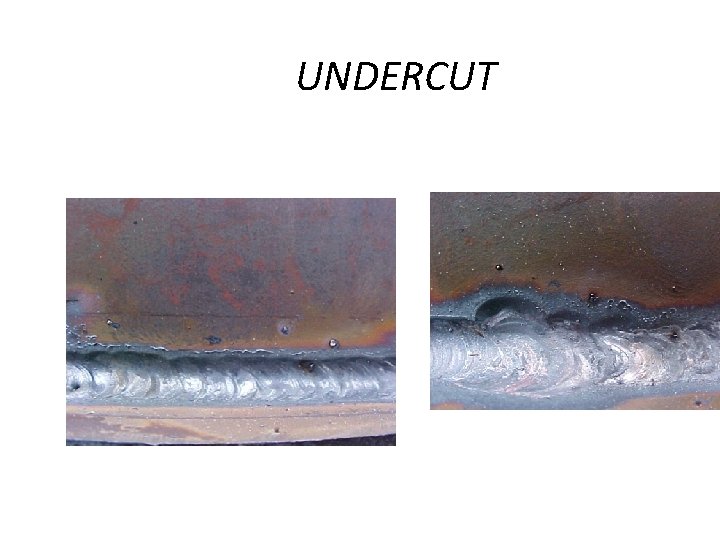
UNDERCUT
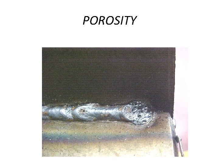
POROSITY
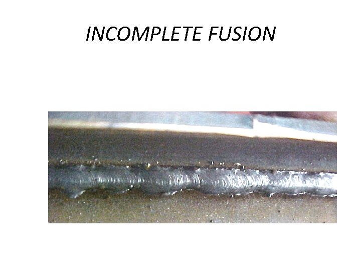
INCOMPLETE FUSION
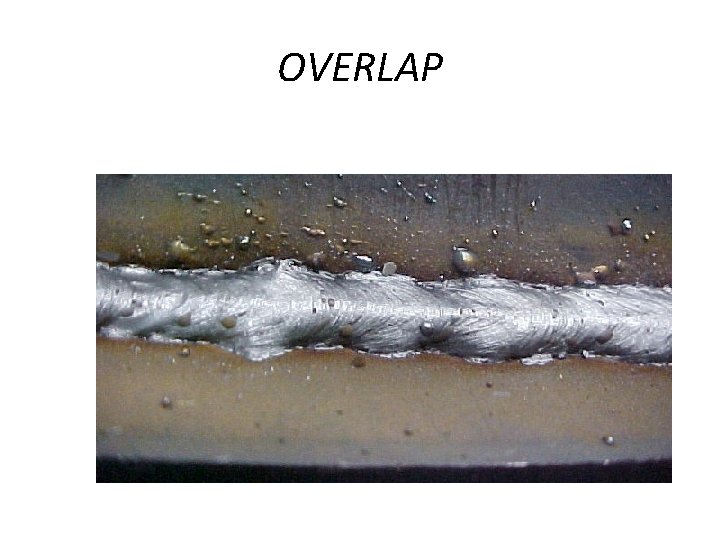
OVERLAP
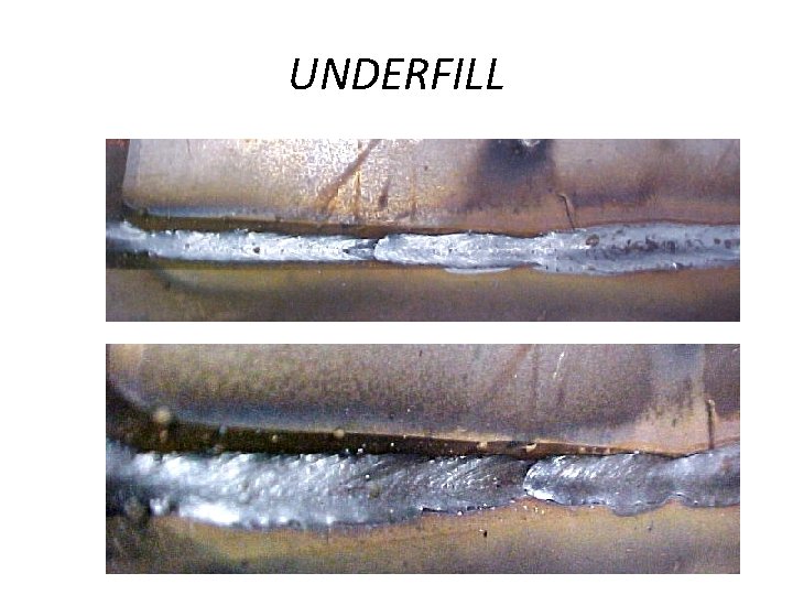
UNDERFILL
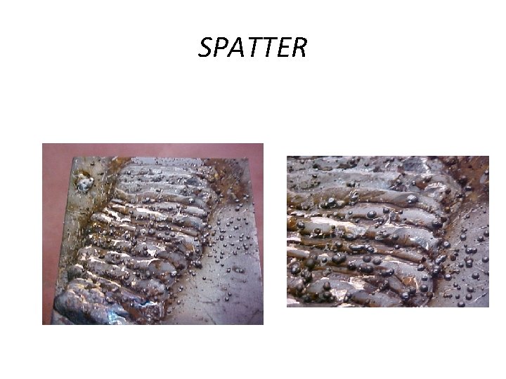
SPATTER
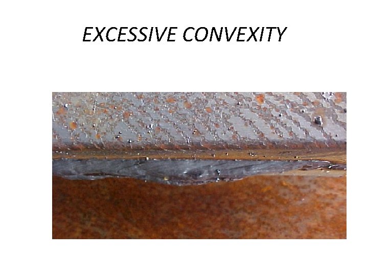
EXCESSIVE CONVEXITY
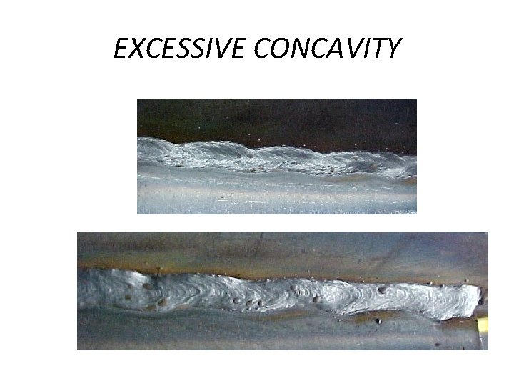
EXCESSIVE CONCAVITY
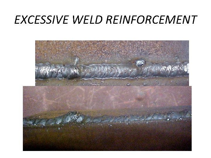
EXCESSIVE WELD REINFORCEMENT
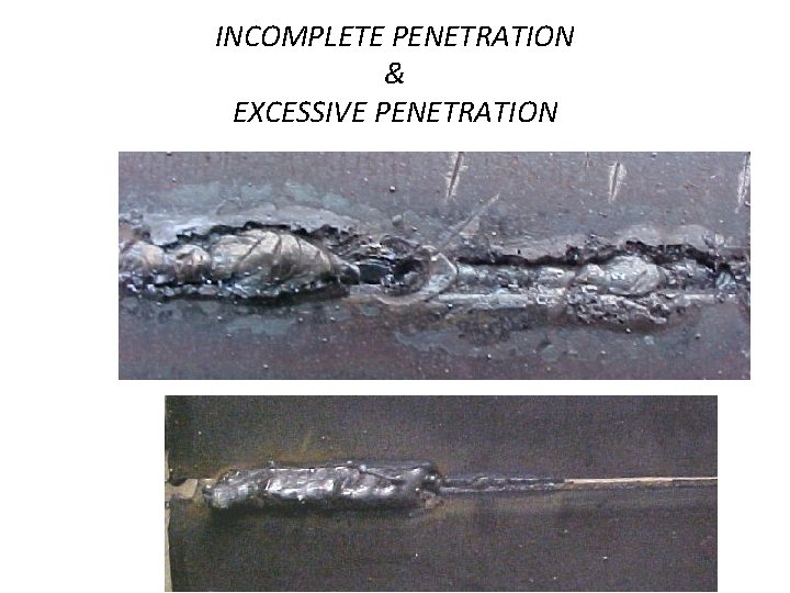
INCOMPLETE PENETRATION & EXCESSIVE PENETRATION
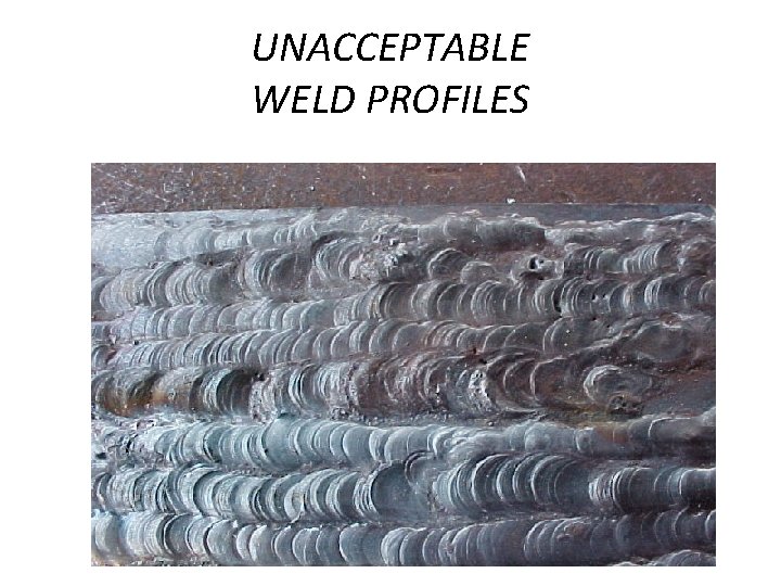
UNACCEPTABLE WELD PROFILES
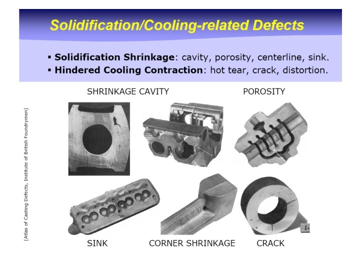
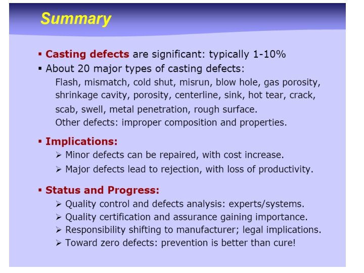
Casting Defects • Metal casters try to produce perfect castings. • A few castings, however, are completely free of defects. • Modern foundries have sophisticated inspection equipment which can detect small differences in size and a wide variety of external and even internal defects. For example, slight shrinkage on the back of a decorative wall plaque is acceptable whereas similar shrinkage on a position cannot be tolerated. • No matter what the intended use, however, the goal of modern foundries is zero defects in all castings
• Scrap castings cause much concern. • In industry, scrap results in smaller profits for the company and ultimately affects individual wages. • Scrap meetings are held daily. Managers of all the major departments attend these meetings. They gather castings that have been identified as scrap by inspector. The defect is circled with chalk. An effort is made to analyze the cause of the defect, and the manager whose department was responsible for it is directed to take corrective action to eliminate that specific defect in future castings. • There are so many variables in the production of a metal casting that the cause is often a combination of several factors rather than a single one. • All pertinent data related to the production of the casting (sand core properties, pouring temperature) must be known in order to identify the defect correctly. • After the defect is identified attempt should be to eliminate the defect by taking appropriate corrective action.
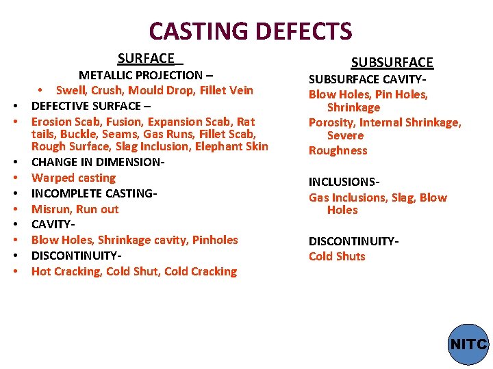
CASTING DEFECTS SURFACE • • • METALLIC PROJECTION – • Swell, Crush, Mould Drop, Fillet Vein DEFECTIVE SURFACE – Erosion Scab, Fusion, Expansion Scab, Rat tails, Buckle, Seams, Gas Runs, Fillet Scab, Rough Surface, Slag Inclusion, Elephant Skin CHANGE IN DIMENSIONWarped casting INCOMPLETE CASTINGMisrun, Run out CAVITYBlow Holes, Shrinkage cavity, Pinholes DISCONTINUITYHot Cracking, Cold Shut, Cold Cracking SUBSURFACE CAVITYBlow Holes, Pin Holes, Shrinkage Porosity, Internal Shrinkage, Severe Roughness INCLUSIONSGas Inclusions, Slag, Blow Holes DISCONTINUITYCold Shuts NITC
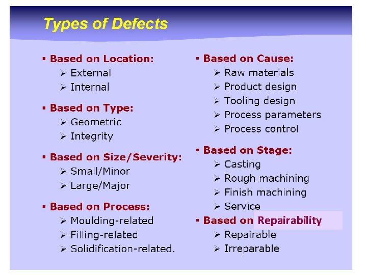
Repairability
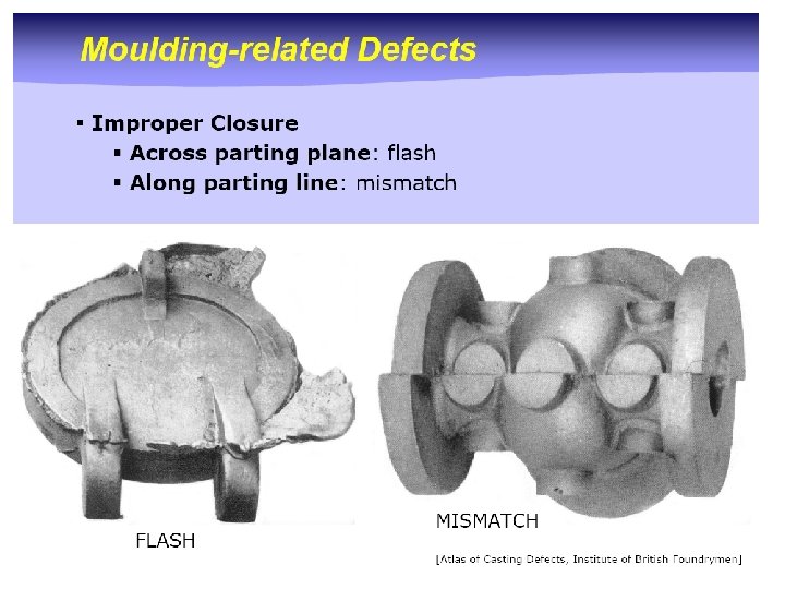
FINS OR FLASH ON CASTINGS -As. Metallic Projections • Joint flash or fins. Flat projection of irregular thickness, often with lacy edges, perpendicular to one of the faces of the casting. It occurs along the joint or parting line of the mold, at a core print, or wherever two elements of the mold intersect. • Possible Causes • Clearance between two elements of the mold or between mold and core; • Poorly fit mold joint. • Remedies • Care in pattern making, molding and core making; • Control of their dimensions; • Care in core setting and mold assembly; • Sealing of joints where possible.
• • • Flask was disturbed while investment was setting. Base was removed too soon. Flask was allowed to partially dry before dewaxing. Incorrect dewaxing or a furnace malfunction. Flask burned out and allowed to cool below (260 o. C) before casting reheating, flask allowed to cool between dewax and placement in preheated oven. Flask was improperly handled or dropped. Speed was set too high on centrifugal casting machine. Patterns were placed on one plane. The should be staggered on top rack. Incorrect water powder ratio was used. Not enough investment was placed over the patterns. Flask was placed too close to heat source in burnout oven. Flasks were not held at low burnout temperature long enough.
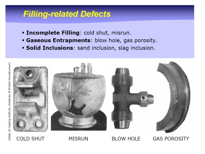
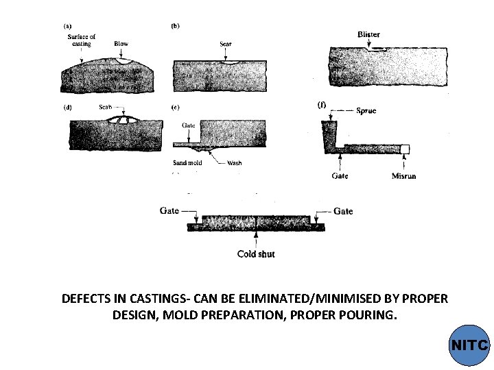
DEFECTS IN CASTINGS- CAN BE ELIMINATED/MINIMISED BY PROPER DESIGN, MOLD PREPARATION, PROPER POURING. NITC
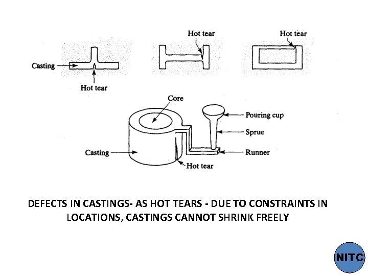
DEFECTS IN CASTINGS- AS HOT TEARS - DUE TO CONSTRAINTS IN LOCATIONS, CASTINGS CANNOT SHRINK FREELY NITC
Cavities • Blowholes, pinholes. Smooth-walled cavities, essentially spherical, often not contacting the external casting surface (blowholes). The largest cavities are most often isolated; the smallest (pinholes) appear in groups of varying dimensions. • The interior walls of blowholes and pinholes can be shiny, more or less oxidized or, in the case of cast iron, can be covered with a thin layer of graphite. The defect can appear in all regions of the casting.
• Possible Causes • Because of gas entrapped in the metal during the course of solidification: • Excessive gas content in metal bath (charge materials, melting method, atmosphere, etc. ); Dissolved gases are released during solidification. • In steel and cast irons: formation of carbon monoxide by the reaction of carbon and oxygen, presents as a gas or in oxide form. Blowholes from carbon monoxide may increase in size by diffusion of hydrogen or, less often, nitrogen. • Excessive moisture in molds or cores. • Core binders which liberate large amounts of gas. • Excessive amounts of additives containing hydrocarbons. • Blacking and washes which tend to liberate too much gas. • Insufficient evacuation of air and gas from the mold cavity; insufficient mold and core permeability. • Entrainment of air due to turbulence in the runner system.
• Remedies • Make adequate provision for evacuation of air and gas from the mold cavity • Increase permeability of mold and cores • Avoid improper gating systems • Assure adequate baking of dry sand molds • Control moisture levels in green sand molding • Reduce amounts of binders and additives used or change to other types; -use blackings and washes, which provide a reducing atmosphere; -keep the spree filled and reduce pouring height • Increase static pressure by enlarging runner height.
Discontinuities • Hot cracking. A crack often scarcely visible because the casting in general has not separated into fragments. The fracture surfaces may be discolored because of oxidation. The design of the casting is such that the crack would not be expected to result from constraints during cooling. • Possible Causes • Damage to the casting while hot due to rough handling or excessive temperature at shakeout. • Remedies • Care in shakeout and in handling the casting while it is still hot; • Sufficient cooling of the casting in the mold; • For metallic molds; delay knockout, assure mold alignment, use ejector pins
Defective Surface • Flow marks. On the surfaces of otherwise sound castings, the defect appears as lines which trace the flow of the streams of liquid metal. • • Possible Causes • Oxide films which lodge at the surface, partially marking the paths of metal flow through the mold. Remedies Increase mold temperature; Lower the pouring temperature; Modify gate size and location (for permanent molding by gravity or low pressure); • Tilt the mold during pouring; • In die casting: vapor blast or sand blast mold surfaces which are perpendicular, or nearly perpendicular, to the mold parting line. • •
Incomplete Casting • Poured short. The upper portion of the casting is missing. The edges adjacent to the missing section are slightly rounded, all other contours conform to the pattern. The spree, risers and lateral vents are filled only to the same height above the parting line, as is the casting (contrary to what is observed in the case of defect). • Possible Causes • Insufficient quantity of liquid metal in the ladle; • Premature interruption of pouring due to workman’s error. • • Remedies Have sufficient metal in the ladle to fill the mold; Check the gating system; Instruct pouring crew and supervise pouring practice.
Incorrect Dimensions or Shape • Distorted casting. Inadequate thickness, extending over large areas of the cope or drag surfaces at the time the mold is rammed. • Possible Causes • Rigidity of the pattern or pattern plate is not sufficient to withstand the ramming pressure applied to the sand. The result is an elastic deformation of the pattern and a corresponding, permanent deformation of the mold cavity. In diagnosing the condition, the compare the surfaces of the pattern with those of the mold itself. • Remedy • Assure adequate rigidity of patterns and pattern plates, especially when squeeze pressures are being increased.
Inclusions or Structural Anomalies • Metallic Inclusions. Metallic or intermetallic inclusions of various sizes which are distinctly different in structure and color from the base material, and most especially different in properties. These defects most often appear after machining. • Possible Causes • Combinations formed as intermetallics between the melt and metallic impurities (foreign impurities); • Charge materials or alloy additions which have not completely dissolved in the melt; • Exposed core wires or rods; • During solidification, insoluble intermetallic compounds form and segregate, concentrating in the residual liquid. • Remedies • Assure that charge materials are clean; eliminate foreign metals; • Use small pieces of alloying material and master alloys in making up the charge; • Be sure that the bath is hot enough when making the additions; • Do not make addition too near to the time of pouring; • For nonferrous alloys, protect cast iron crucibles with a suitable wash
• INCLUSIONS (FOREIGN PARTICLES) IN CASTINGS • Patterns were improperly sprued to wax base or tree or not filleted, causing investment to break at sharp corners during casting. • Flask was not sufficiently cured before placing into burnout oven. • Improper dewaxing cycle was used. • Flask was not cleaned from prior cast. • Loose investment in sprue hole. • Molten metal contains excess flux or foreign oxides. • Crucible disintegrating or poorly fluxed. • Improperly dried graphite crucible. • Investment was not mixed properly or long enough. • Contaminants in wax pattern. • Flask was not held at low burnout temperature long enough. • Flask was placed too close to heat source in burnout oven.
• POROSITY • Pattern is improperly sprued. Sprues may be too thin, too long or not attached in the proper location, causing shrinkage porosity. • Not enough metal reservoir to eliminate shrinkage porosity. • Metal contains gas. • Mold is too hot. • Too much moisture in the flux. • Too much remelt being used. Always use at least 50% new metal. • Metal is overheated. • Poor mold burnout.
• ROUGH CASTINGS • A poor quality pattern • Flask was not sufficiently cured before placing into burnout oven. • Flask was held in steam dewax too long. • Metal, flask or both were too hot. • Patterns were improperly sprued. • Flask was placed too close to heat source in burnout oven.
BUBBLES OR NODULES ON CASTINGS Vacuum pump is leaking air. Vacuum pump has water in the oil. Vacuum pump is low on oil. Investment not mixed properly or long enough. Invested flasks were not vibrated during vacuum cycle. • Vacuum extended past working time. • • •
• SPALLING (an area of the mold wall flakes into the mold cavity) • Flask was placed into a furnace at low temperature (below 150 o. C) for an extended period. • Flask was placed too close to the source of heat. • Sharp corners are struck by metal at high centrifugal velocities. • Improper burnout cycle was used.
NON-FILL OR INCOMPLETE CASTINGS Metal was too cold when cast. Mold was too cold when cast. The burnout was not complete. Pattern was improperly sprued, creating turbulence when casting in a centrifugal casting machine. • Centrifugal casting machine had too high revolution per minute. • • •
• GROWTH-LIKE ROUGH CASTING THAT RESISTS REMOVAL IN PICKLING SOLUTION • Burnout temperature too high. • Mold temperature was too high when casting. • Metal temperature was too high when casting.
• SHINY CASTINGS • Carbon residue was left in the mold, creating a reducing condition on the surface.
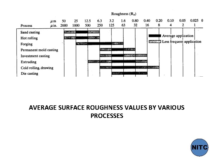
AVERAGE SURFACE ROUGHNESS VALUES BY VARIOUS PROCESSES NITC
DESIGN CONSIDERATIONS CAREFUL CONTROL OF LARGE NUMBER OF VARIABLES NEEDED • CHARACTERISTICS OF METALS & ALLOYS CAST • METHOD OF CASTING • MOULD AND DIE MATERIALS • MOULD DESIGN • PROCESS PARAMETERS- POURING, TEMPERATURE, • GATING SYSTEM • RATE OF COOLING Etc. NITC
• Poor casting practices, lack of control of process variables. DEFECTIVE CASTINGS • TO AVOID DEFECTS • Basic economic factors relevant to casting operations to be studied. • General guidelines applied for all types of castings to be studied. DESIGN CONSIDERATIONS NITC
CORNERS, ANGLES AND SECTION THICKNESS • Sharp corners, angles, fillets to be avoided Cause cracking and tearing during solidification • Fillet radii selection to ensure proper liquid metal flow- 3 mm to 25 mm. Too large- volume large & rate of cooling less • Location with largest circle inscribed critical. Cooling rate less shrinkage cavities & porosities result. Called HOT SPOTS NITC
DESIGN MODIFICATIONS TO AVOID DEFECTS- AVOID SHARP CORNERS MAINTAIN UNIFORM CROSS SECTIONS AVOID SHRINKAGE CAVITIES USE CHILLS TO INCREASE THE RATE OF COOLING STAGGER INTERSECTING REGIONS FOR UNIFORM CROSS SECTIONS • REDESIGN BY MAKING PARTING LINE STRAIGHT • AVOID THE USE OF CORES, IF POSSIBLE • MAINTAIN SECTION THICKNESS UNIFORMITY BY REDESIGNING (in die cast products) • • • NITC
• LARGE FLAT AREAS TO BE AVOIDED- • • • WARPING DUE TO TEMPERATURE GRADIENTS ALLOWANCES FOR SHRINKAGE TO BE PROVIDED PARTING LINE TO BE ALONG A FLAT PLANEGOOD AT CORNERS OR EDGES OF CASTING DRAFT TO BE PROVIDED PERMISSIBLE TOLERANCES TO BE USED MACHINING ALLOWANCES TO BE MADE RESIDUAL STRESSES TO BE AVOIDED ALL THESE FOR EXPENDABLE MOULD CASTINGS. NITC
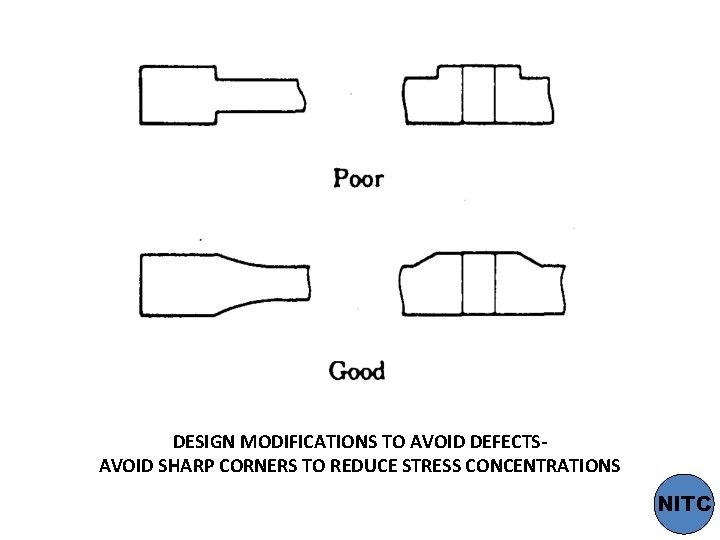
DESIGN MODIFICATIONS TO AVOID DEFECTSAVOID SHARP CORNERS TO REDUCE STRESS CONCENTRATIONS NITC
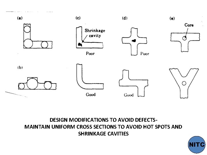
DESIGN MODIFICATIONS TO AVOID DEFECTSMAINTAIN UNIFORM CROSS SECTIONS TO AVOID HOT SPOTS AND SHRINKAGE CAVITIES NITC
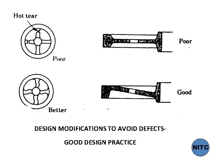
DESIGN MODIFICATIONS TO AVOID DEFECTSGOOD DESIGN PRACTICE NITC
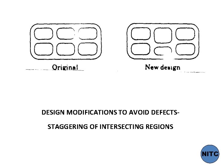
DESIGN MODIFICATIONS TO AVOID DEFECTSSTAGGERING OF INTERSECTING REGIONS NITC
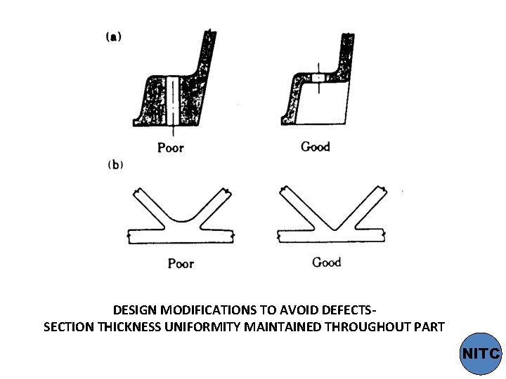
DESIGN MODIFICATIONS TO AVOID DEFECTSSECTION THICKNESS UNIFORMITY MAINTAINED THROUGHOUT PART NITC
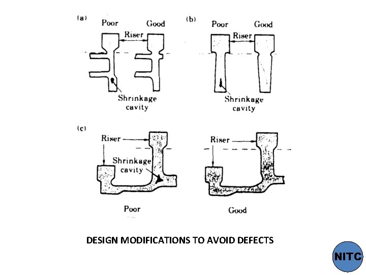
DESIGN MODIFICATIONS TO AVOID DEFECTS NITC
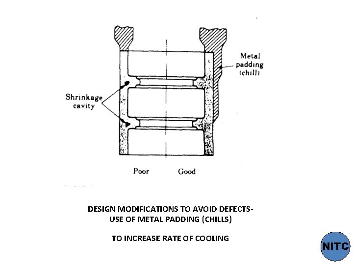
DESIGN MODIFICATIONS TO AVOID DEFECTSUSE OF METAL PADDING (CHILLS) TO INCREASE RATE OF COOLING NITC
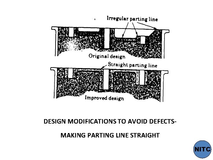
DESIGN MODIFICATIONS TO AVOID DEFECTSMAKING PARTING LINE STRAIGHT NITC
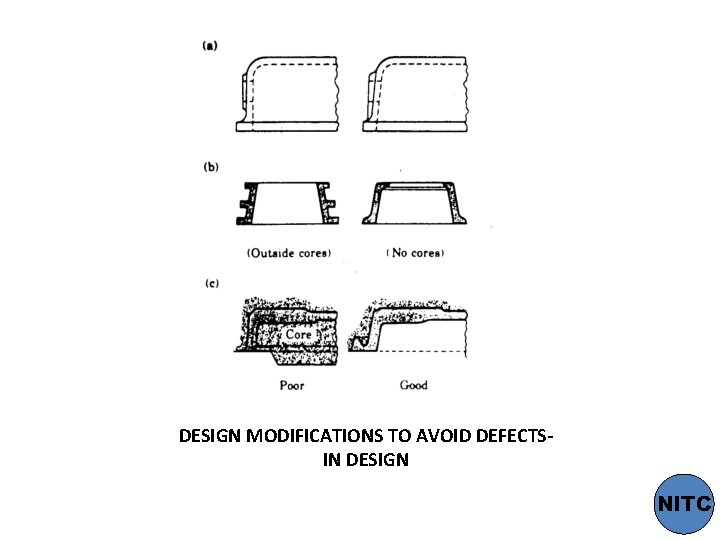
DESIGN MODIFICATIONS TO AVOID DEFECTSIN DESIGN NITC
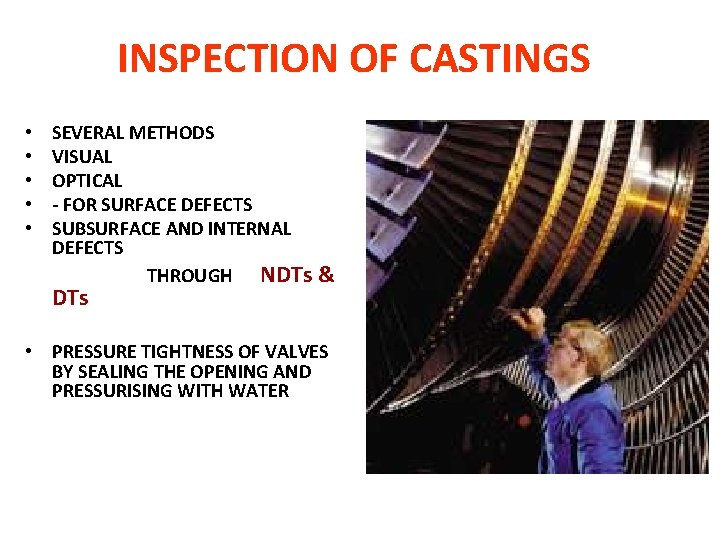
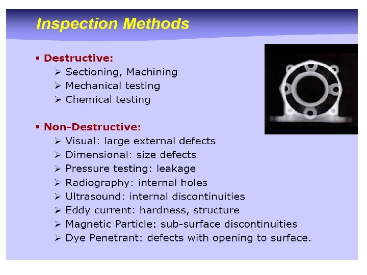
INSPECTION OF CASTINGS • • • SEVERAL METHODS VISUAL OPTICAL - FOR SURFACE DEFECTS SUBSURFACE AND INTERNAL DEFECTS THROUGH NDTs & DTs • PRESSURE TIGHTNESS OF VALVES BY SEALING THE OPENING AND PRESSURISING WITH WATER
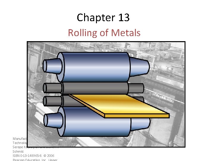
Chapter 13 Rolling of Metals Manufacturing, Engineering & Technology, Fifth Edition, by Serope Kalpakjian and Steven R. Schmid. ISBN 0 -13 -148965 -8. © 2006
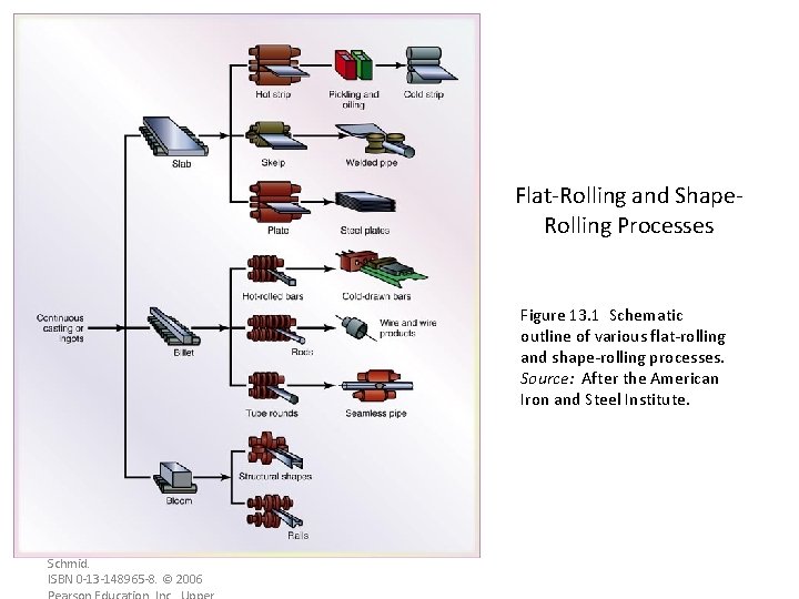
Flat-Rolling and Shape. Rolling Processes Figure 13. 1 Schematic outline of various flat-rolling and shape-rolling processes. Source: After the American Iron and Steel Institute. Manufacturing, Engineering & Technology, Fifth Edition, by Serope Kalpakjian and Steven R. Schmid. ISBN 0 -13 -148965 -8. © 2006
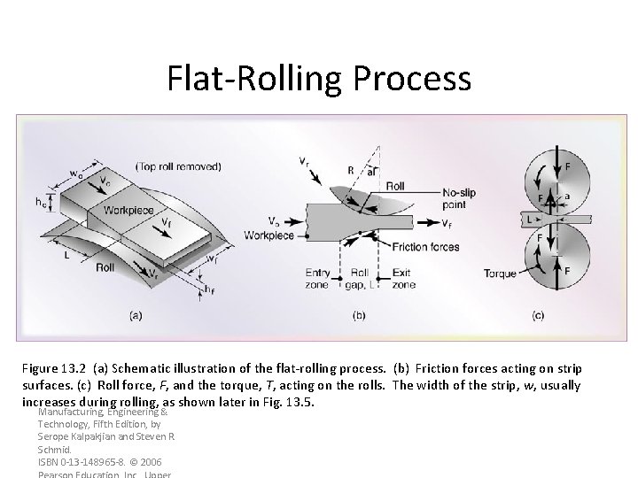
Flat-Rolling Process Figure 13. 2 (a) Schematic illustration of the flat-rolling process. (b) Friction forces acting on strip surfaces. (c) Roll force, F, and the torque, T, acting on the rolls. The width of the strip, w, usually increases during rolling, as shown later in Fig. 13. 5. Manufacturing, Engineering & Technology, Fifth Edition, by Serope Kalpakjian and Steven R. Schmid. ISBN 0 -13 -148965 -8. © 2006
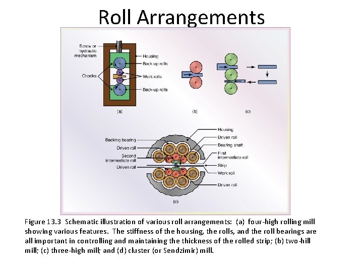
Roll Arrangements Figure 13. 3 Schematic illustration of various roll arrangements: (a) four-high rolling mill showing various features. The stiffness of the housing, the rolls, and the roll bearings are all important in controlling and maintaining the thickness of the rolled strip; (b) two-hill mill; (c) three-high mill; and (d) cluster (or Sendzimir) mill.
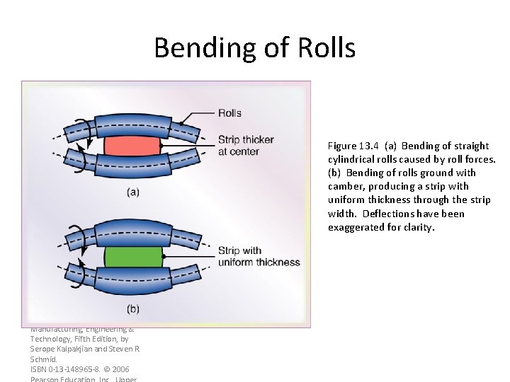
Bending of Rolls Figure 13. 4 (a) Bending of straight cylindrical rolls caused by roll forces. (b) Bending of rolls ground with camber, producing a strip with uniform thickness through the strip width. Deflections have been exaggerated for clarity. Manufacturing, Engineering & Technology, Fifth Edition, by Serope Kalpakjian and Steven R. Schmid. ISBN 0 -13 -148965 -8. © 2006
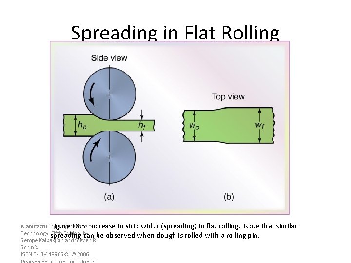
Spreading in Flat Rolling Manufacturing, Engineering & Figure 13. 5 Increase in strip width (spreading) in flat rolling. Note that similar Technology, Fifth Edition, by spreading can be observed when dough is rolled with a rolling pin. Serope Kalpakjian and Steven R. Schmid. ISBN 0 -13 -148965 -8. © 2006
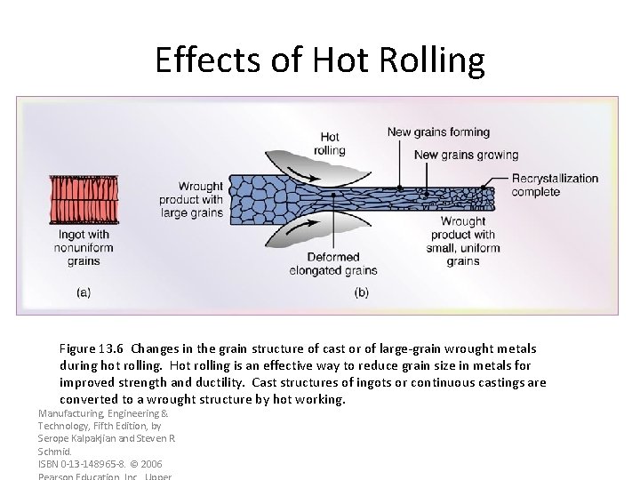
Effects of Hot Rolling Figure 13. 6 Changes in the grain structure of cast or of large-grain wrought metals during hot rolling. Hot rolling is an effective way to reduce grain size in metals for improved strength and ductility. Cast structures of ingots or continuous castings are converted to a wrought structure by hot working. Manufacturing, Engineering & Technology, Fifth Edition, by Serope Kalpakjian and Steven R. Schmid. ISBN 0 -13 -148965 -8. © 2006
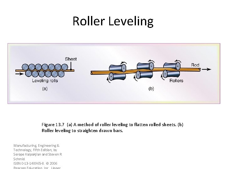
Roller Leveling Figure 13. 7 (a) A method of roller leveling to flatten rolled sheets. (b) Roller leveling to straighten drawn bars. Manufacturing, Engineering & Technology, Fifth Edition, by Serope Kalpakjian and Steven R. Schmid. ISBN 0 -13 -148965 -8. © 2006
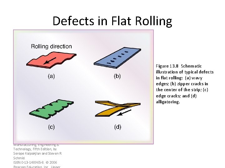
Defects in Flat Rolling Figure 13. 8 Schematic illustration of typical defects in flat rolling: (a) wavy edges; (b) zipper cracks in the center of the strip; (c) edge cracks; and (d) alligatoring. Manufacturing, Engineering & Technology, Fifth Edition, by Serope Kalpakjian and Steven R. Schmid. ISBN 0 -13 -148965 -8. © 2006
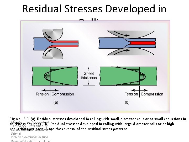
Residual Stresses Developed in Rolling Figure 13. 9 (a) Residual stresses developed in rolling with small-diameter rolls or at small reductions in Manufacturing, Engineering & thickness per pass. (b) Residual stresses developed in rolling with large-diameter rolls or at high Technology, Fifth Edition, by reductions per pass. Note the reversal of the residual stress patterns. Serope Kalpakjian and Steven R. Schmid. ISBN 0 -13 -148965 -8. © 2006
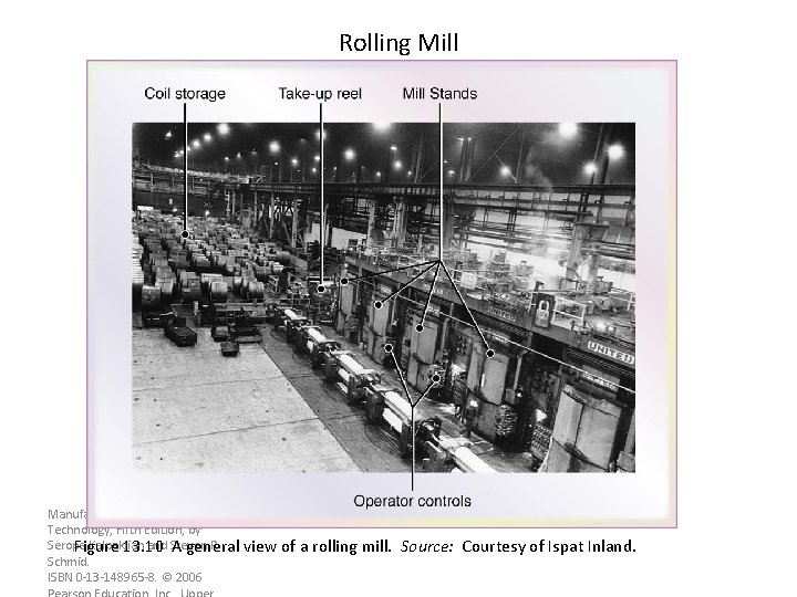
Rolling Mill Manufacturing, Engineering & Technology, Fifth Edition, by Serope Kalpakjian and Steven R. Figure 13. 10 A general view of a rolling mill. Source: Courtesy of Ispat Inland. Schmid. ISBN 0 -13 -148965 -8. © 2006
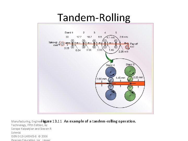
Tandem-Rolling Manufacturing, Engineering & Figure 13. 11 An example of a tandem-rolling operation. Technology, Fifth Edition, by Serope Kalpakjian and Steven R. Schmid. ISBN 0 -13 -148965 -8. © 2006
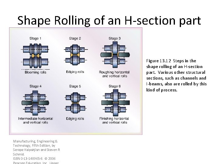
Shape Rolling of an H-section part Figure 13. 12 Steps in the shape rolling of an H-section part. Various other structural sections, such as channels and I-beams, also are rolled by this kind of process. Manufacturing, Engineering & Technology, Fifth Edition, by Serope Kalpakjian and Steven R. Schmid. ISBN 0 -13 -148965 -8. © 2006
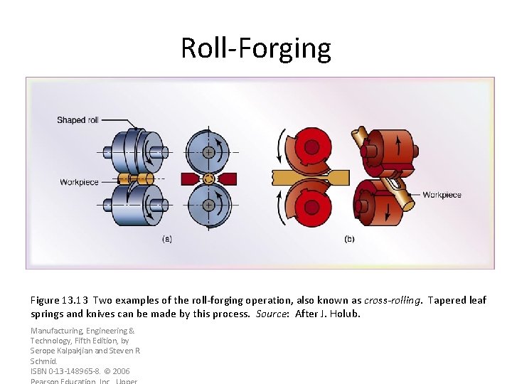
Roll-Forging Figure 13. 13 Two examples of the roll-forging operation, also known as cross-rolling. Tapered leaf springs and knives can be made by this process. Source: After J. Holub. Manufacturing, Engineering & Technology, Fifth Edition, by Serope Kalpakjian and Steven R. Schmid. ISBN 0 -13 -148965 -8. © 2006
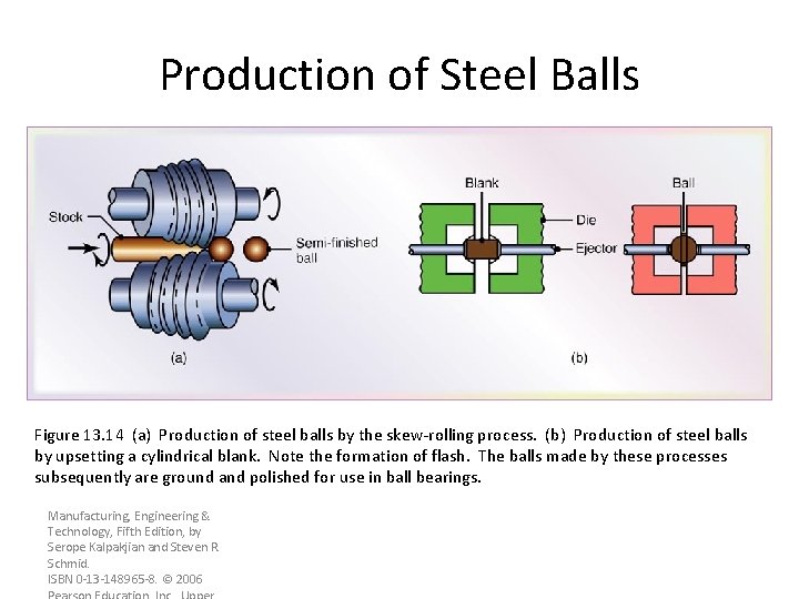
Production of Steel Balls Figure 13. 14 (a) Production of steel balls by the skew-rolling process. (b) Production of steel balls by upsetting a cylindrical blank. Note the formation of flash. The balls made by these processes subsequently are ground and polished for use in ball bearings. Manufacturing, Engineering & Technology, Fifth Edition, by Serope Kalpakjian and Steven R. Schmid. ISBN 0 -13 -148965 -8. © 2006
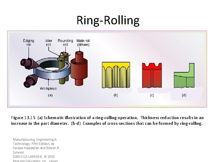
Ring-Rolling Figure 13. 15 (a) Schematic illustration of a ring-rolling operation. Thickness reduction results in an increase in the part diameter. (b-d) Examples of cross-sections that can be formed by ring-rolling. Manufacturing, Engineering & Technology, Fifth Edition, by Serope Kalpakjian and Steven R. Schmid. ISBN 0 -13 -148965 -8. © 2006
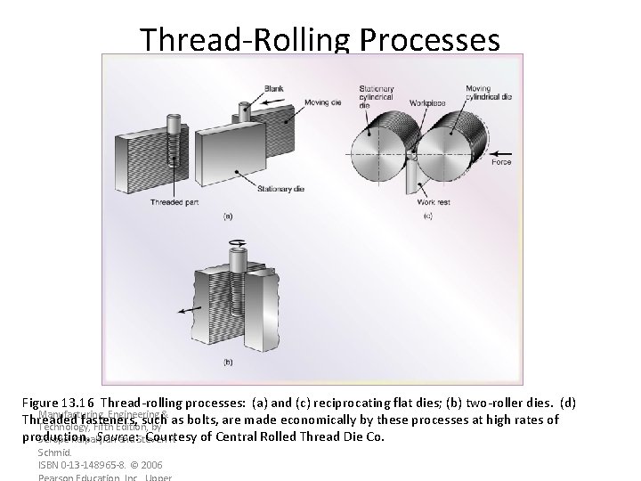
Thread-Rolling Processes Figure 13. 16 Thread-rolling processes: (a) and (c) reciprocating flat dies; (b) two-roller dies. (d) Manufacturing, Engineering & Threaded fasteners, such as bolts, are made economically by these processes at high rates of Technology, Fifth Edition, by production. Source: Courtesy of Central Rolled Thread Die Co. Serope Kalpakjian and Steven R. Schmid. ISBN 0 -13 -148965 -8. © 2006
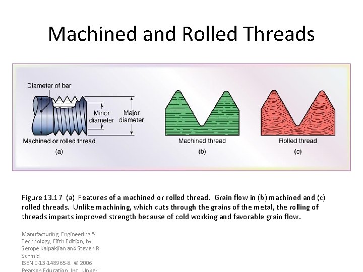
Machined and Rolled Threads Figure 13. 17 (a) Features of a machined or rolled thread. Grain flow in (b) machined and (c) rolled threads. Unlike machining, which cuts through the grains of the metal, the rolling of threads imparts improved strength because of cold working and favorable grain flow. Manufacturing, Engineering & Technology, Fifth Edition, by Serope Kalpakjian and Steven R. Schmid. ISBN 0 -13 -148965 -8. © 2006
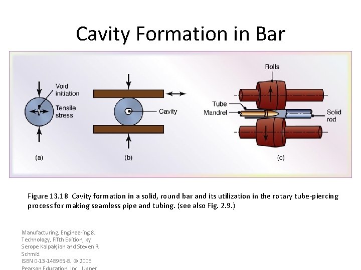
Cavity Formation in Bar Figure 13. 18 Cavity formation in a solid, round bar and its utilization in the rotary tube-piercing process for making seamless pipe and tubing. (see also Fig. 2. 9. ) Manufacturing, Engineering & Technology, Fifth Edition, by Serope Kalpakjian and Steven R. Schmid. ISBN 0 -13 -148965 -8. © 2006
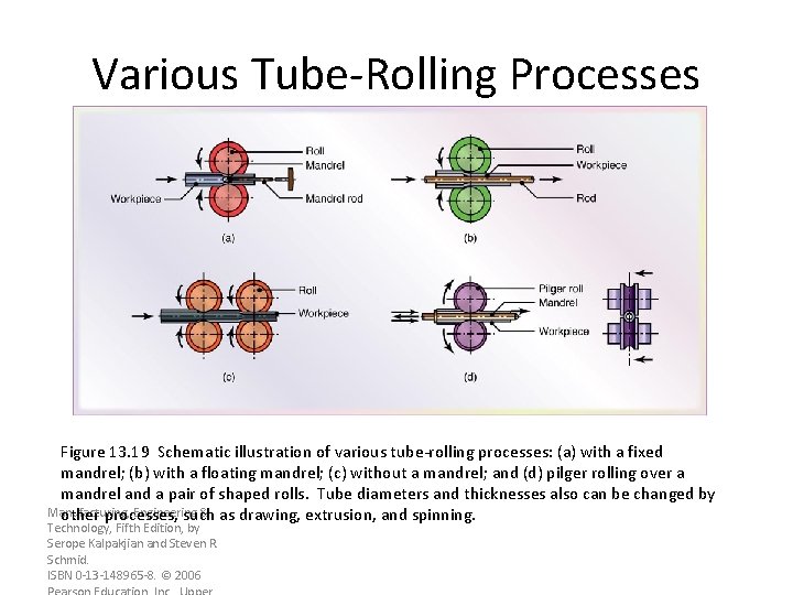
Various Tube-Rolling Processes Figure 13. 19 Schematic illustration of various tube-rolling processes: (a) with a fixed mandrel; (b) with a floating mandrel; (c) without a mandrel; and (d) pilger rolling over a mandrel and a pair of shaped rolls. Tube diameters and thicknesses also can be changed by Manufacturing, Engineering & other processes, such as drawing, extrusion, and spinning. Technology, Fifth Edition, by Serope Kalpakjian and Steven R. Schmid. ISBN 0 -13 -148965 -8. © 2006
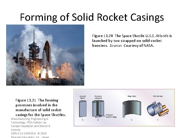
Forming of Solid Rocket Casings Figure 13. 20 The Space Shuttle U. S. S. Atlantis is launched by two strapped-on solid-rocket boosters. Source: Courtesy of NASA. Figure 13. 21 The forming processes involved in the manufacture of solid rocket casings for the Space Shuttles. Manufacturing, Engineering & Technology, Fifth Edition, by Serope Kalpakjian and Steven R. Schmid. ISBN 0 -13 -148965 -8. © 2006
- Slides: 84