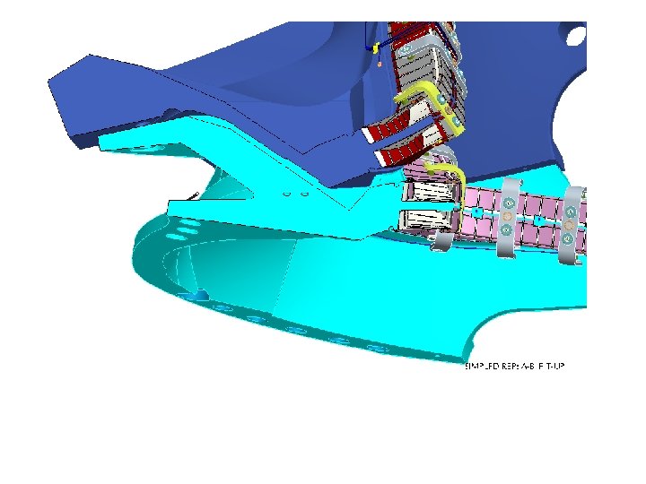
Weld Support post welded between wings it can

Weld Support post welded between wings – it can be insulated We plan to improve the process by providing supports on the wing.

Notes • Peening – we need to determine how efficient it is. Still learning. IN PROCESS. • Weld cooling – can it do much to control deflections? • Post weld heat treatment. (heating elements or induction – call Cooperheat) What temperature is needed? Can we keep the coil T within 125 C limits? • Bracing – temporary or permant? Insulated or non-insulated?

Plan going forward • • Weld tests indicate wing deflection in the range of 30 -40 mils due to weldinduced distortion. Our goal is to reduce this by at least 50%: – Use of stepped shims to reduce tendancy of a gap opening up inboard of the weld as weld shrinks. • Investigate the possibility of welding the “plasma side” of the shims to the extent possible. Ex: 9 of 15 of A-B; 4 -5 of 20 on B-C; none on A-A. – Further investigation of weld peening (but limited because root and cover pass welds cannot be peened). – Bracing or clamping between wings. Could provide adjustment. (Development plans being made). – Investigation of thermal stress relief. – Cryo cooling of welds (i. e. W 7 X method). • Proceed with the current machine assembly plans modified: – As planned, assemble A 1 and B 1 with spec alumina coated shims fitted per procedures and actual bolt kits. • Use stepped shims fully fitted to spec on inboard side. – Modification: • add wing braces – Develop designs for all 3 assemblies. – Determine if temporary or permanent and if fixed or adjustable. • Modify peening & weld thermal /cryo stress relief plans based on A 6/B 6 results and investigations. – If deflections makes spec, it will become the first production part.
- Slides: 6