
WBS 2 7 4 Breakout Detector Controls DCS
WBS 2. 7. 4 Breakout Detector Controls (DCS) A. Norman (U. Virginia) L 3 Manager June 16, 2009
Detector Controls & Monitoring: Overview • What is the “D. C. S”? – It is the unified collection of detector controls, readout monitoring systems – It controls all non-DAQ specific configuration parameters for hardware systems – It controls some DAQ specific configuration parameters, but only for hardware systems – It monitors all critical operational parameters – It handles the generation of alarm and logging messages for the system using these parameters – It interfaces to the main databases • This is the User’s (and Run Control’s) window into controlling NOνA June 16 -18, 2009 Director's CD-3 b Review A. Norman, WBS 2. 7. 4 Manager 2
Detector Controls & Monitoring: Status • Full system design established – Heavily leveraged off of EPICs libraries – Designs for specific hardware readout exist where hardware has been established – Preliminary [generic] designs for hardware readout exist where hardware has not been finalized – Prototype [standalone] readouts have been developed or leveraged for key systems still being evaluated – Implementations of some subsystems have been started • Completion requires final hardware choices • Completion requires final DAQ interaction specifications • DCS design is approximately 90% complete June 16 -18, 2009 Director's CD-3 b Review A. Norman, WBS 2. 7. 4 Manager 3
Overview • • • Scope Hardware Computing Networking Software Design Integration June 16 -18, 2009 Director's CD-3 b Review A. Norman, WBS 2. 7. 4 Manager 4
Detector Controls & Monitoring SCOPE June 16 -18, 2009 Director's CD-3 b Review A. Norman, WBS 2. 7. 4 Manager 5
Scope: Controls • The DCS is designed to handle the programmable controls, monitoring, alarm handling, and state logging for the major detector subsystems – Power Control and Distribution • High Voltage Bias • Low Voltage power – – – – Water pumping and cooling Data Concentrator Modules (DCM) Front End Boards (FEB) PVC Stress/strain sensors Timing/Sync modules Environmental parameters and monitoring Rack monitoring • The DCS needs to provide the local state logging as well as interfacing with the primary database server for long term logging and system history • The DCS needs to provide a feedback loop into the DAQ system to handle system faults and run stop conditions June 16 -18, 2009 Director's CD-3 b Review A. Norman, WBS 2. 7. 4 Manager 6
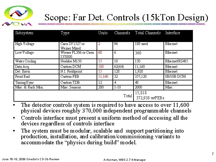
Scope: Far Det. Controls (15 k. Ton Design) Subsystem Type Units Channels Total Channels Interface High Voltage 2 96 180 used Ethernet 60 6 360 Ethernet Water Cooling Data Acq. Det. Envir. Front End Caen SY 1527 or Weiner Mpod Wiener PL 506 or Caen SY 8800 Neslabs M 150 Custom DCM N. I. Fieldpoint Custom FEB 15 180 15 11, 160 10 62(64) 128 32 150 11, 160 1, 920 357, 120 Ethernet/RS 485 Ethernet 8 B/10 B DCM Timing/Sync Misc. & Rack Mon. Custom TDB Misc. Sensors 12 200 4 1 -10 48 2000 Ethernet Misc. Low Voltage 15, 818 Total 372, 938 w/FEBs • The detector controls system is required to have access to over 11, 600 physical devices roughly 370, 000 independent programmable channels • Controls interface must present a uniform method of accessing all the devices regardless of controls interface • The system must be modular, scalable and support partitioning into production, installation, and calibration/commissioning variants to accommodate the “physics during build” model. 7 June 16 -18, 2009 Director's CD-3 b Review A. Norman, WBS 2. 7. 4 Manager
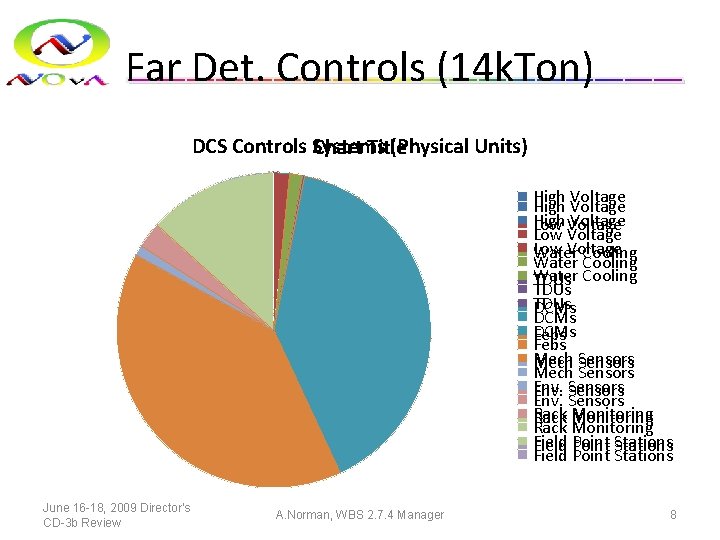
Far Det. Controls (14 k. Ton) DCS Controls Systems (Physical Units) Chart Title High Voltage Low Voltage Water Cooling TDUs DCMs Febs Mech Sensors Env. Sensors Rack Monitoring Field Point Stations June 16 -18, 2009 Director's CD-3 b Review A. Norman, WBS 2. 7. 4 Manager 8
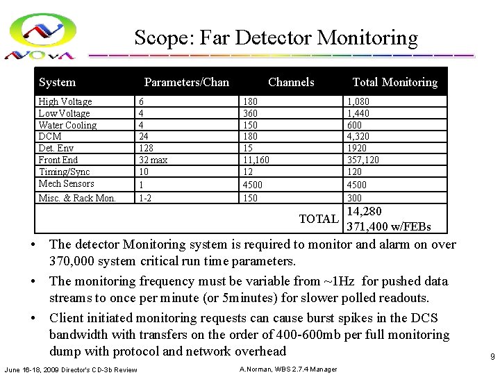
Scope: Far Detector Monitoring System High Voltage Low Voltage Water Cooling DCM Det. Env Front End Timing/Sync Mech Sensors Misc. & Rack Mon. Parameters/Chan 6 4 4 24 128 32 max 10 1 1 -2 Channels 180 360 150 180 15 11, 160 12 4500 150 Total Monitoring 1, 080 1, 440 600 4, 320 1920 357, 120 4500 300 TOTAL 14, 280 371, 400 w/FEBs • The detector Monitoring system is required to monitor and alarm on over 370, 000 system critical run time parameters. • The monitoring frequency must be variable from ~1 Hz for pushed data streams to once per minute (or 5 minutes) for slower polled readouts. • Client initiated monitoring requests can cause burst spikes in the DCS bandwidth with transfers on the order of 400 -600 mb per full monitoring dump with protocol and network overhead June 16 -18, 2009 Director's CD-3 b Review A. Norman, WBS 2. 7. 4 Manager 9
Detector Controls HARDWARE June 16 -18, 2009 Director's CD-3 b Review A. Norman, WBS 2. 7. 4 Manager 10
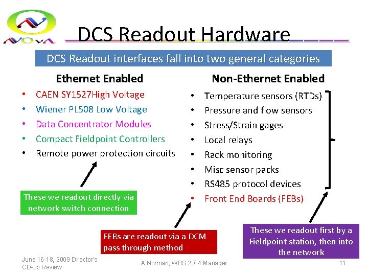
DCS Readout Hardware DCS Readout interfaces fall into two general categories Ethernet Enabled • • • CAEN SY 1527 High Voltage Wiener PL 508 Low Voltage Data Concentrator Modules Compact Fieldpoint Controllers Remote power protection circuits These we readout directly via network switch connection Non-Ethernet Enabled • • Temperature sensors (RTDs) Pressure and flow sensors Stress/Strain gages Local relays Rack monitoring Misc sensor packs RS 485 protocol devices Front End Boards (FEBs) FEBs are readout via a DCM pass through method June 16 -18, 2009 Director's CD-3 b Review A. Norman, WBS 2. 7. 4 Manager These we readout first by a Fieldpoint station, then into the network 11
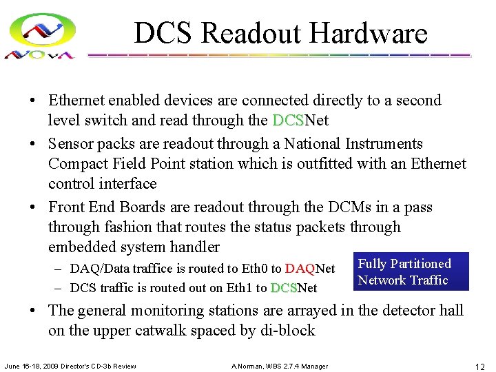
DCS Readout Hardware • Ethernet enabled devices are connected directly to a second level switch and read through the DCSNet • Sensor packs are readout through a National Instruments Compact Field Point station which is outfitted with an Ethernet control interface • Front End Boards are readout through the DCMs in a pass through fashion that routes the status packets through embedded system handler – DAQ/Data traffice is routed to Eth 0 to DAQNet – DCS traffic is routed out on Eth 1 to DCSNet Fully Partitioned Network Traffic • The general monitoring stations are arrayed in the detector hall on the upper catwalk spaced by di-block June 16 -18, 2009 Director's CD-3 b Review A. Norman, WBS 2. 7. 4 Manager 12

DCSNet Network Topology Voltage IOC DCSNet Voltage Chan Serv Secondary Switch FEB Chan Serv FEB Chan Serv Master DCS Switch FEB IOC FEB IOC Fiber Connect Master Channel Server ENV. IOC DCSNet Env. Chan Serv Field Point Unit Field Point. Unit Point Sensors Env. Sensors Secondary Switch HV HVSupply DCM Chan Serv DCM IOC LV Supply LV LVSupply DCSNet DAQNet Client Controls and Monitoring Applications NOv. A CD-2/3 a Review Breakout Run Control A. Norman (U. Virginia) DCM FEB FEB FEBs 13

DCS Network Overview DCS Chan. Server/IOC DCS Master Server 1 (Displays and Controls) DCSNet DCS User Client DCS Chan. Server/IOC DCS Local Logger (4 TB storage) Error Logger DCSNet KVM Switch DCS Chan. Server/IOC Access from the control room is from the master control station or from client stations connected to the DCSNet Far site Control Room Detector hall access to DCS is through mobile laptop over the DCSNet Wireless access points. DCSNet Wireless DCSNet Far Site Electronics Room DCS Master Server 2 (Displays and Controls) Database Server (FNAL/Feynman CD) Remote DCS User Client Detector Hall Controls Access NOv. A CD-2/3 a Review Breakout Access from the FNAL control room is via a VPN style secure point to point connection that extends the DCSNet to the second control master, and remote user clients FNAL site Control Room A. Norman (U. Virginia) 14
Detector Controls SOFTWARE NOv. A CD-2/3 a Review Breakout A. Norman (U. Virginia) 15
DCS Client Software • Based off of QT 4 and ROOT 5 with interfaces to EPICS 3. 14 • Currently working under QT 4. 2. x and QT-ROOT 5. x • Runs under Sci Linux 4. x and all Microsoft Windows XP/Vista distributions • Provides a platform independent development API for creating the client interfaces. • Client applications are portable and can be deployed on multiple platforms • Everything is standard C++ compatible with standard GCC (linux) and Visual C/mingw (MS Windows) • Results in high performance clients • Visualization is accomplished by direct use of the ROOT histogram and plotting libraries. • Component widgets are standardized and manageable. • Full integration with ROOT 5. x complete under QT 4 NOv. A CD-2/3 a Review Breakout A. Norman (U. Virginia) 16
DCS Server Software • • Core system based off of EPICS developed at ANL Development started under base release R 3. 14 (Feb 2007 Rel. ) Runs under Sci. Linux 4. x as well as Fedora Core Provides a Client/Server type architecture and communications protocol Operates under the concept of distributed Input/Output controllers with universal channel naming and access conventions Provides the majority of the transaction protocol, local state monitoring and channel history and access models Currently EPICS drivers exist for some of our hardware – – – • Need to develop drivers for – – • • Caen SY 1527 N. I. Fieldpoints Generic Ethernet device (base module) Wiener LV supplies RS 485 based devices (Standard OPCs will not work since we are using Linux OS) DCMs (model off the basic Ethernet device) FEBs (via DCM interface) Overhead and performance based on tests by ANL EPICS group, and from implementations at D 0, were extrapolated to determine that NOv. A will require 12 PCs to handle the monitoring/controls load (50 k records per server). System is scalable. We can additional IOCs to support new devices, or additional servers to support higher loads. NOv. A CD-2/3 a Review Breakout A. Norman (U. Virginia) 17
Hardware Interfaces • Interfaces follow vendor specific specs – Not possible to fully implement hardware/software interface layer till final specs and devices are prototyped/procurred • Currently have samples for testing of: – Fieldpoint Readout Stations – Weiner PL 508 & Mpod (ISEG HV) – Caen SY 1527 HV and SY 8800 LV – DCM Prototype + Firmware June 16 -18, 2009 Director's CD-3 b Review A. Norman, WBS 2. 7. 4 Manager 18
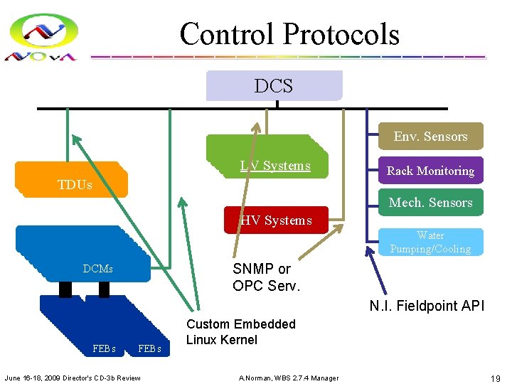
Control Protocols DCS TDUs HV Systems HV LVSystems Env. Sensors Rack Monitoring Mech. Sensors HV Systems DCMs DCMs FEBs FEBs FEBs FEBs FEBs FEBs FEBs FEBs FEBs FEBs FEBs June 16 -18, 2009 Director's CD-3 b Review Water Pumping/Cooling SNMP or OPC Serv. N. I. Fieldpoint API Custom Embedded Linux Kernel A. Norman, WBS 2. 7. 4 Manager 19
DCM Embedded Software • DCM runs a Power. PC single board computer – Standard chip, compilation rules exist • Requires three types of Software development – Operating System • Custom Linux • Network boot, small memory foot print – Hardware driver • Custom Kernel module with support for FPGA and buses – DAQ clients • FPGA loader, DAQ inits, DAQ Readout, Buffer manager, Network dispatch • DCS client (readout/monitor/dispatch) June 16 -18, 2009 Director's CD-3 b Review A. Norman, WBS 2. 7. 4 Manager 20
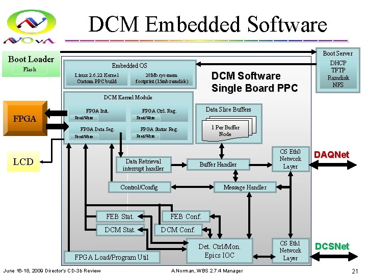
DCM Embedded Software Boot Loader Flash Embedded OS Linux 2. 6. 22 Kernel Custom PPC build DCM Software Single Board PPC 28 Mb sys-mem footprint (15 mb ramdisk) DCM Kernel Module FPGA Read/Write 1 Per Buffer Node FPGA Status Reg. FPGA Data Seg. Read/Write LCD Data Slice Buffers FPGA Ctrl. Reg. FPGA Init. Data Retrieval interrupt handler Buffer Handler Control/Config FEB Stat. DCM Stat. FPGA Load/Program Util June 16 -18, 2009 Director's CD-3 b Review Boot Server DHCP TFTP Ramdisk NFS OS Eth 0 Network Layer DAQNet OS Eth 1 Network Layer DCSNet Message Handler FEB Conf. DCM Conf. Det. Ctrl/Mon. Epics IOC A. Norman, WBS 2. 7. 4 Manager 21
Preliminary Design • Some systems have not been fully prototyped or demo models are not available • We still design the preliminary readouts – Allows for modular design and integration with the EPIC IOC structure – Created state level diagrams for hardware/driver interaction – Implementation of the state machines can be tested and debugged using other control systems (e. g. Labview) – Allows for development of lightweight “test” clients which do not rely on full EPICs infrastructure June 16 -18, 2009 Director's CD-3 b Review A. Norman, WBS 2. 7. 4 Manager 22
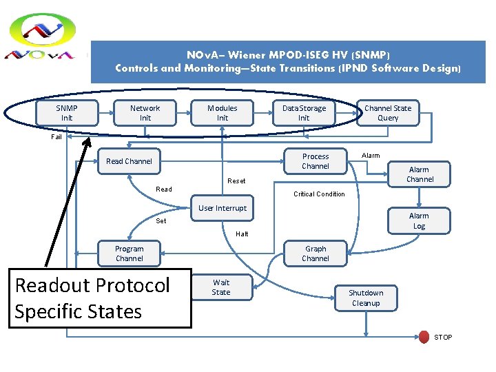
NOv. A– Wiener MPOD-ISEG HV (SNMP) Controls and Monitoring—State Transitions (IPND Software Design) SNMP Init Network Init Modules Init Data Storage Init Channel State Query Fail Process Channel Read Channel Alarm Channel Reset Read Critical Condition User Interrupt Alarm Log Set Halt Graph Channel Program Channel Readout Protocol Specific States Wait State Shutdown Cleanup STOP
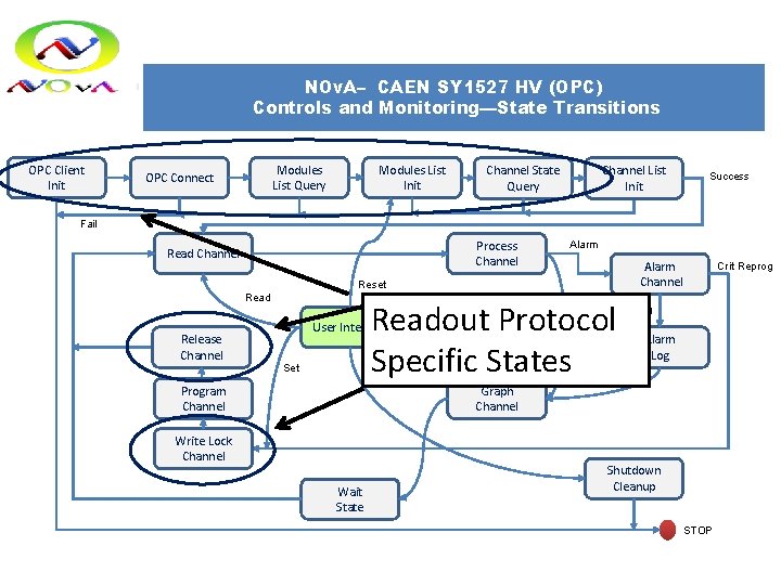
NOv. A– CAEN SY 1527 HV (OPC) Controls and Monitoring—State Transitions OPC Client Init Modules List Query OPC Connect Channel State Query Channel List Init Success Fail Process Channel Read Channel Alarm Channel Reset Read Release Channel Readout Protocol Specific States Critical Condition User Interrupt Set Halt Crit Reprog Log Alarm Log Graph Channel Program Channel Write Lock Channel Wait State Shutdown Cleanup STOP
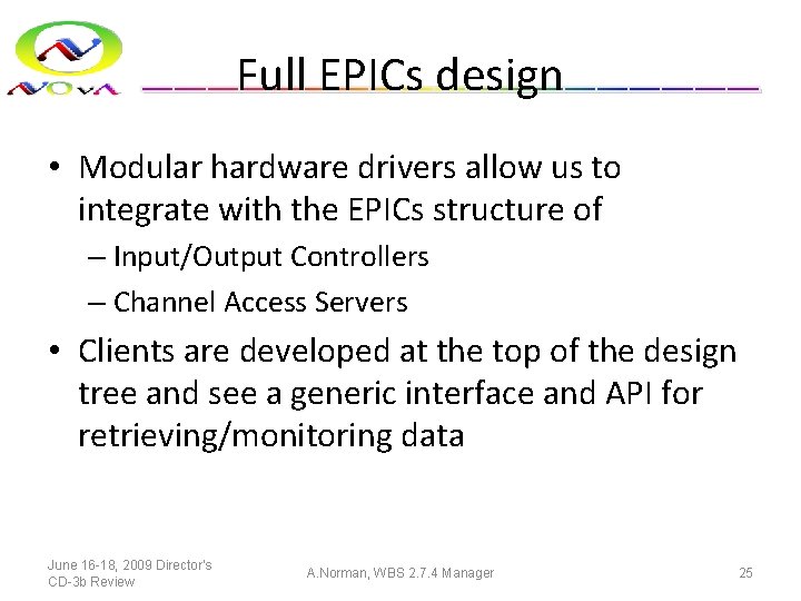
Full EPICs design • Modular hardware drivers allow us to integrate with the EPICs structure of – Input/Output Controllers – Channel Access Servers • Clients are developed at the top of the design tree and see a generic interface and API for retrieving/monitoring data June 16 -18, 2009 Director's CD-3 b Review A. Norman, WBS 2. 7. 4 Manager 25
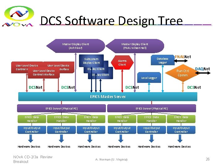
DCS Software Design Tree Master Display Client (Ash River) User Level Device Control Interface DCSNet Master Display Client (FNAL Wilson Hall) Subsystem Display Client DCSNet Database Logger Alarms Client Local Logger FNALNet Run Ctrl. Comm. DAQNet DCSNet EPICS Master Server EPICS Server (Physical PC) EPICS Data Handler EPICS Data Handler Input/Output Controller Input/Output Controller Hardware Devices Hardware Devices NOv. A CD-2/3 a Review Breakout A. Norman (U. Virginia) 26
DCS/DAQ Integration • Det. Controls must interact with the main DAQ system – Provides access to program devices – Provides state/fault information – Acts as a general feed back channel for hardware operations • Not the same as the data quality monitor (DQM) • Not the same as the DAQ health monitor (DAQmon) June 16 -18, 2009 Director's CD-3 b Review A. Norman, WBS 2. 7. 4 Manager 27
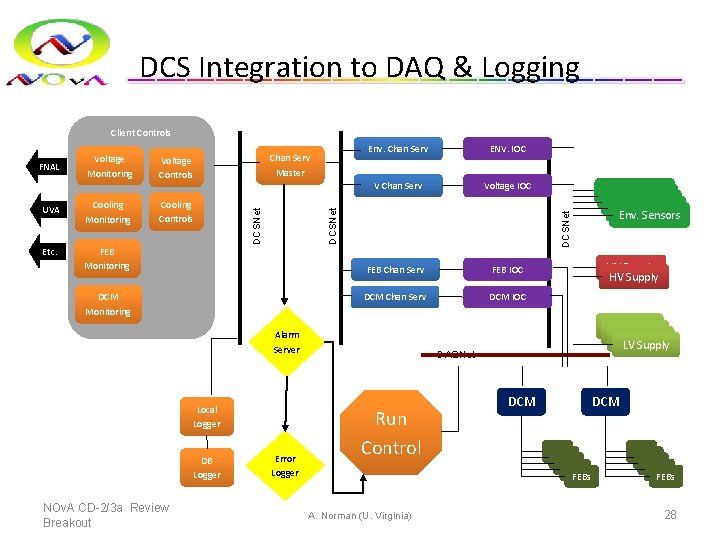
DCS Integration to DAQ & Logging Client Controls Etc. FEB Monitoring ENV. IOC V Chan Serv Voltage IOC FEB Chan Serv FEB IOC DCM Monitoring DCM Chan Serv DCM IOC DCSNet Cooling Monitoring Cooling Controls Env. Chan Serv DCSNet UVA Chan Serv Master Voltage Controls DCSNet FNAL Voltage Monitoring Alarm Server Local Logger DB Logger NOv. A CD-2/3 a Review Breakout Error Logger HV Supply LV Supply DAQNet Run Control A. Norman (U. Virginia) Env. Sensors DCM FEB FEB FEBs 28
DCS/DAQ Integration • Many subsystems share development paths between DCS and DAQ • Primary system is the DCM – Kernel module developed to support both data stacks and monitoring data stacks – Client apps are being developed for both data path and dcs path in tandem – This inherits down to the FEB level since the DCM is the transport mechanism for talking to the FEBs June 16 -18, 2009 Director's CD-3 b Review A. Norman, WBS 2. 7. 4 Manager 29
Detector Mass Based BACKUP SLIDES NOv. A CD-2/3 a Review Breakout A. Norman (U. Virginia) 30
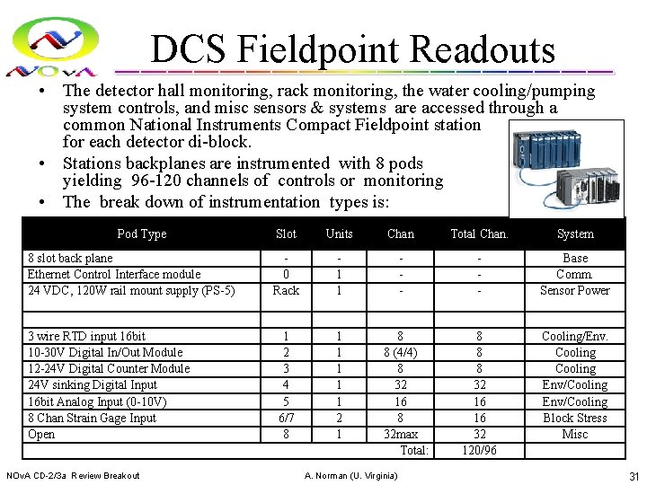
DCS Fieldpoint Readouts • The detector hall monitoring, rack monitoring, the water cooling/pumping system controls, and misc sensors & systems are accessed through a common National Instruments Compact Fieldpoint station for each detector di-block. • Stations backplanes are instrumented with 8 pods yielding 96 -120 channels of controls or monitoring • The break down of instrumentation types is: Pod Type 8 slot back plane Ethernet Control Interface module 24 VDC, 120 W rail mount supply (PS-5) 3 wire RTD input 16 bit 10 -30 V Digital In/Out Module 12 -24 V Digital Counter Module 24 V sinking Digital Input 16 bit Analog Input (0 -10 V) 8 Chan Strain Gage Input Open NOv. A CD-2/3 a Review Breakout Slot Units Chan Total Chan. System 0 Rack 1 1 - - Base Comm. Sensor Power 1 2 3 4 5 6/7 8 1 1 1 2 1 8 8 8 32 16 16 32 120/96 Cooling/Env. Cooling Env/Cooling Block Stress Misc 8 8 (4/4) 8 32 16 8 32 max Total: A. Norman (U. Virginia) 31
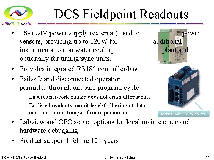
DCS Fieldpoint Readouts • PS-5 24 V power supply (external) used to sensors, providing up to 120 W for instrumentation on water cooling optionally for timing/sync units. • Provides integrated RS 485 controller/bus • Failsafe and disconnected operation permitted through onboard program cycle – Ensures network outage does not crash all readouts – Buffered readouts permit level-0 filtering of data and short term storage of some parameters power additional plant and Includes RS 485/232 controllers • Labview and OPC server options for local maintenance and hardware debugging. • Product support lifetime 10+ years NOv. A CD-2/3 a Review Breakout A. Norman (U. Virginia) 32
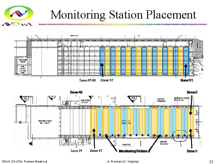
Monitoring Station Placement Zone 17 Zone 1 Zone 40 Zone 2 Zone 17 NOv. A CD-2/3 a Review Breakout Monitoring Stations A. Norman (U. Virginia) Zone 1 33
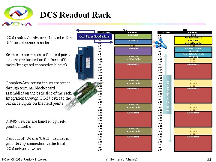
DCS Readout Rack Front DCS readout hardware is housed in the di-block electronics racks Simple sensor inputs to the field point stations are located on the front of the racks (integrated connection blocks) Complex/Aux sensor inputs are routed through terminal block/board assemblies on the back side of the rack. Integration through DB 37 cable to the backside inputs on the field points RS 485 devices are handled by Field point controller. Readout of Wiener/CAEN devices is provided by connection to the local DCS network switch NOv. A CD-2/3 a Review Breakout Gbit Fiber U-1 (to U-2 Master) U-3 U-4 U-5 U-6 U-7 U-8 U-9 U-10 U-11 U-12 U-13 U-14 U-15 U-16 U-17 U-18 U-19 U-20 U-21 U-22 U-23 U-24 U-25 U-26 U-27 U-28 U-29 U-30 U-31 U-32 U-33 U-34 U-35 U-36 U-37 U-38 U-39 U-40 U-41 U-42 U-43 U-44 Equipment DAQ Switch DCS Switch Air Gap Field Point Exaust Fans (3 x 70 mm muffin) Wiener PL 508 A. Norman (U. Virginia) Back Position U-1 U-2 U-3 U-4 U-5 U-6 U-7 U-8 U-9 U-10 U-11 U-12 U-13 U-14 U-15 U-16 U-17 U-18 U-19 U-20 U-21 U-22 U-23 U-24 U-25 U-26 U-27 U-28 U-29 U-30 U-31 U-32 U-33 U-34 U-35 U-36 U-37 U-38 U-39 U-40 U-41 U-42 U-43 U-44 100 Mb Ethernet Position Equipment OPEN Aux. Terminal Block DIN mounted (DB 37 Cable routing) Air Gap 24 V Power supplies (Fieldpoint) Power Distribution Block (Fieldpoint) Air Gap Air Gap Wiener PL 508 Air Gap Wiener PL 508 34
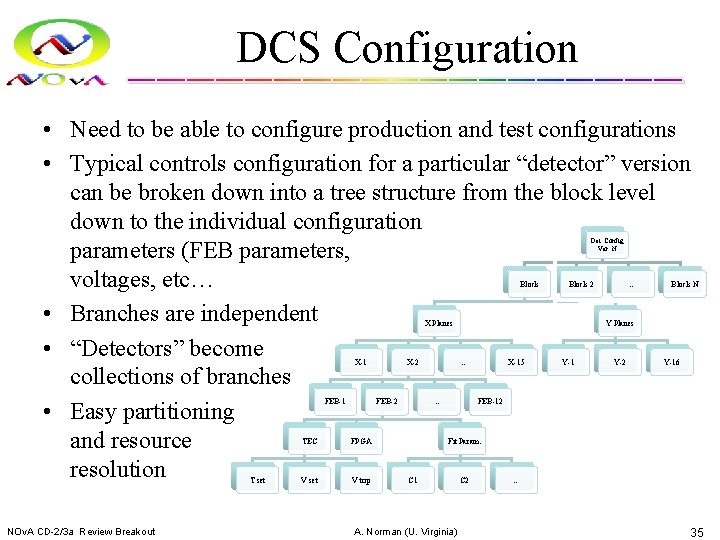
DCS Configuration • Need to be able to configure production and test configurations • Typical controls configuration for a particular “detector” version can be broken down into a tree structure from the block level down to the individual configuration parameters (FEB parameters, voltages, etc… • Branches are independent • “Detectors” become collections of branches • Easy partitioning and resource resolution Det. Config Ver. N Block 2 X Planes X-1 FEB-1 T set NOv. A CD-2/3 a Review Breakout X-2 FEB-2 TEC FPGA V set V trip … Block N Y Planes … … X-15 Y-1 Y-2 Y-16 FEB-12 Fit Param. C 1 A. Norman (U. Virginia) C 2 … 35
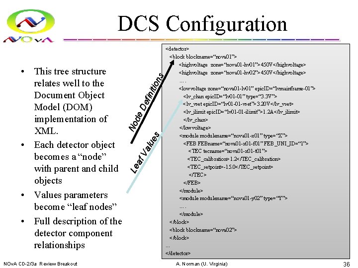
• This tree structure relates well to the Document Object Model (DOM) implementation of XML. • Each detector object becomes a “node” with parent and child objects • Values parameters become “leaf nodes” • Full description of the detector component relationships NOv. A CD-2/3 a Review Breakout No Le de af De Va f ini lu e tion s s DCS Configuration <detector> <blockname=“nova 01”> <highvoltage zone=“nova 01 -hv 01”>450 V</highvoltage> <highvoltage zone=“nova 01 -hv 02”>450 V</highvoltage> …. <lowvoltage zone=“nova 01 -lv 01” epic. ID=“lvmainframe-01”> <lv_chan epic. ID=“lv 01 -01” type=“ 3. 3 V”> <lv_vset epic. ID=“lv 01 -01 -vset”>3. 20 V</lv_vset> <lv_ilimit epic. ID=“lv 01 -01 -ilimit”>1. 2 A</lv_ilimit> </lv_chan> </lowvoltage> <modulename=“nova 01 -x 01” type=“X”> <FEB FEBname=“nova 01 -x 01 -f 01” FEB_UNI_ID=“ 1”> <TEC tecname=“nova 01 -x 01 -t 01”> <TEC_calibration>1. 2</TEC_calibration> <TEC_setpoint>-15. 0</TEC_setpoint> </TEC> </FEB> </module> <modulename=“nova 01 -y 02” type=“Y”> …. </module> </block> <blockname=“nova 02”> </block> … </detector> A. Norman (U. Virginia) 36
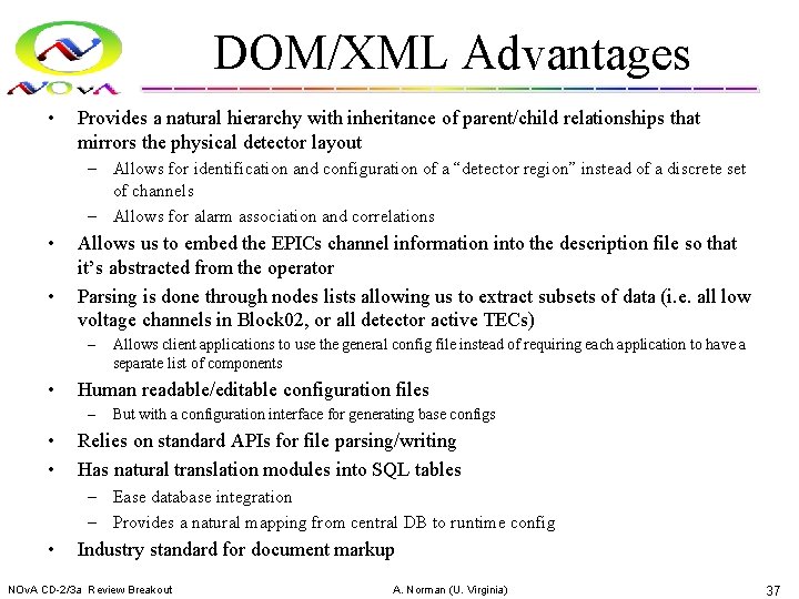
DOM/XML Advantages • Provides a natural hierarchy with inheritance of parent/child relationships that mirrors the physical detector layout – Allows for identification and configuration of a “detector region” instead of a discrete set of channels – Allows for alarm association and correlations • • Allows us to embed the EPICs channel information into the description file so that it’s abstracted from the operator Parsing is done through nodes lists allowing us to extract subsets of data (i. e. all low voltage channels in Block 02, or all detector active TECs) – • Human readable/editable configuration files – • • Allows client applications to use the general config file instead of requiring each application to have a separate list of components But with a configuration interface for generating base configs Relies on standard APIs for file parsing/writing Has natural translation modules into SQL tables – Ease database integration – Provides a natural mapping from central DB to runtime config • Industry standard for document markup NOv. A CD-2/3 a Review Breakout A. Norman (U. Virginia) 37
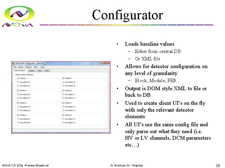
Configurator • Loads baseline values – Either from central DB – Or XML file • Allows for detector configuration on any level of granularity – Block, Module, FEB • • • NOv. A CD-2/3 a Review Breakout Output is DOM style XML to file or back to DB Used to create client UI’s on the fly with only the relevant detector elements All UI’s use the same config file and only parse out what they need (i. e. HV or LV channels, DCM parameters etc…) A. Norman (U. Virginia) 38
Client Building • DCS clients are “built” at run time by parsing the config file and instantiating control widgets into display arrays • Involves no static assumptions about the current detector – Allows for detector growth – Allows for small “test” clients – Allows multiple clients to run in parallel • Channel maps are automatically propagated to clients without rebuilds • EPICs layers are completely abstracted • Requires a central resource manager to resolve resource allocation conflicts NOv. A CD-2/3 a Review Breakout A. Norman (U. Virginia) 39
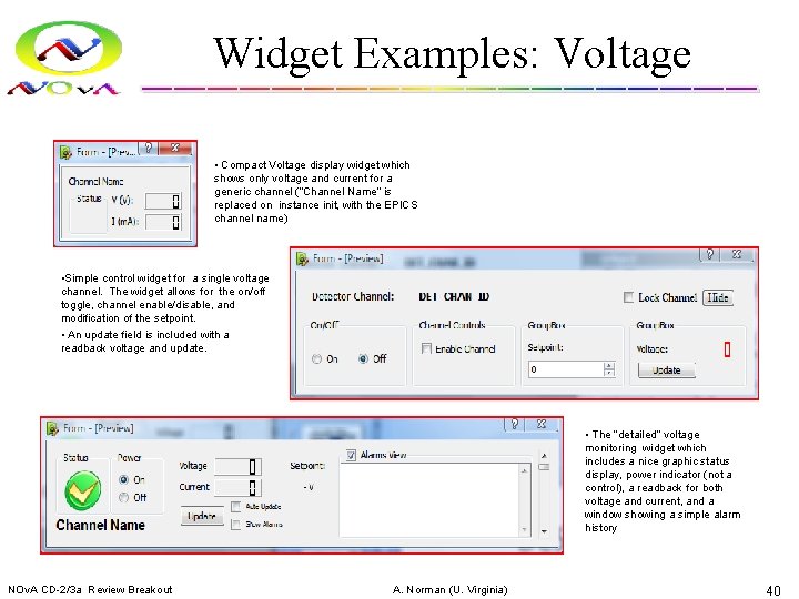
Widget Examples: Voltage • Compact Voltage display widget which shows only voltage and current for a generic channel (“Channel Name” is replaced on instance init, with the EPICS channel name) • Simple control widget for a single voltage channel. The widget allows for the on/off toggle, channel enable/disable, and modification of the setpoint. • An update field is included with a readback voltage and update. • The “detailed” voltage monitoring widget which includes a nice graphic status display, power indicator (not a control), a readback for both voltage and current, and a window showing a simple alarm history NOv. A CD-2/3 a Review Breakout A. Norman (U. Virginia) 40
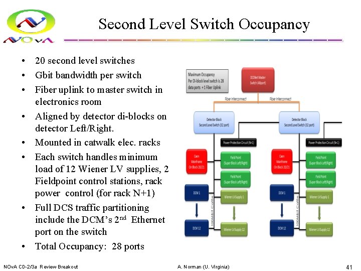
Second Level Switch Occupancy • 20 second level switches • Gbit bandwidth per switch • Fiber uplink to master switch in electronics room • Aligned by detector di-blocks on detector Left/Right. • Mounted in catwalk elec. racks • Each switch handles minimum load of 12 Wiener LV supplies, 2 Fieldpoint control stations, rack power control (for rack N+1) • Full DCS traffic partitioning include the DCM’s 2 nd Ethernet port on the switch • Total Occupancy: 28 ports NOv. A CD-2/3 a Review Breakout A. Norman (U. Virginia) 41
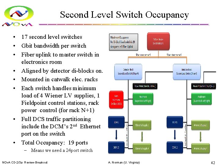
Second Level Switch Occupancy • 17 second level switches • Gbit bandwidth per switch • Fiber uplink to master switch in electronics room • Aligned by detector di-blocks on. • Mounted in catwalk elec. racks • Each switch handles minimum load of 4 Wiener LV supplies, 1 Fieldpoint control stations, rack power control (for rack N+1) • Full DCS traffic partitioning include the DCM’s 2 nd Ethernet port on the switch • Total Occupancy: 19 ports – Means we need a 24 port switch NOv. A CD-2/3 a Review Breakout A. Norman (U. Virginia) 42
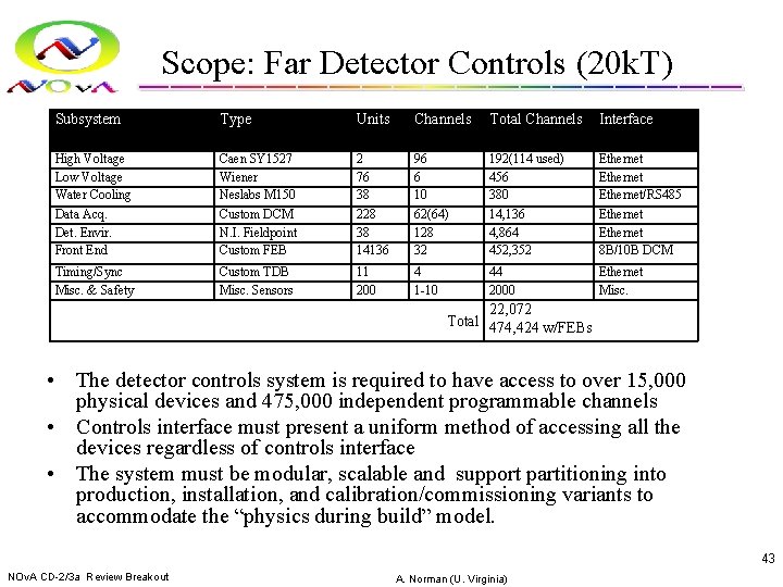
Scope: Far Detector Controls (20 k. T) Subsystem Type Units Channels Total Channels Interface High Voltage Low Voltage Water Cooling Data Acq. Det. Envir. Front End Caen SY 1527 Wiener Neslabs M 150 Custom DCM N. I. Fieldpoint Custom FEB 2 76 38 228 38 14136 96 6 10 62(64) 128 32 192(114 used) 456 380 14, 136 4, 864 452, 352 Ethernet/RS 485 Ethernet 8 B/10 B DCM Timing/Sync Misc. & Safety Custom TDB Misc. Sensors 11 200 4 1 -10 44 2000 Ethernet Misc. 22, 072 Total 474, 424 w/FEBs • The detector controls system is required to have access to over 15, 000 physical devices and 475, 000 independent programmable channels • Controls interface must present a uniform method of accessing all the devices regardless of controls interface • The system must be modular, scalable and support partitioning into production, installation, and calibration/commissioning variants to accommodate the “physics during build” model. 43 NOv. A CD-2/3 a Review Breakout A. Norman (U. Virginia)
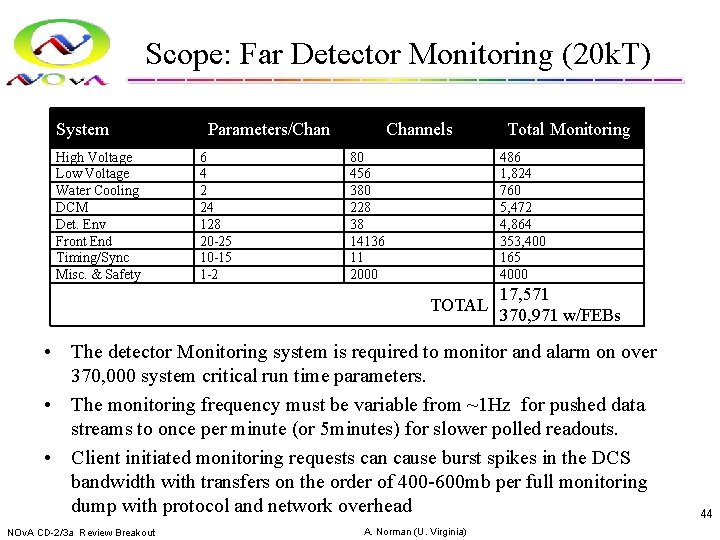
Scope: Far Detector Monitoring (20 k. T) System High Voltage Low Voltage Water Cooling DCM Det. Env Front End Timing/Sync Misc. & Safety Parameters/Chan 6 4 2 24 128 20 -25 10 -15 1 -2 Channels 80 456 380 228 38 14136 11 2000 Total Monitoring 486 1, 824 760 5, 472 4, 864 353, 400 165 4000 TOTAL 17, 571 370, 971 w/FEBs • The detector Monitoring system is required to monitor and alarm on over 370, 000 system critical run time parameters. • The monitoring frequency must be variable from ~1 Hz for pushed data streams to once per minute (or 5 minutes) for slower polled readouts. • Client initiated monitoring requests can cause burst spikes in the DCS bandwidth with transfers on the order of 400 -600 mb per full monitoring dump with protocol and network overhead NOv. A CD-2/3 a Review Breakout A. Norman (U. Virginia) 44
- Slides: 44