Water Pumps o Water pumps are devices designed


 Pumps o Jet pumps capitalize on a high pressure stream")

 Pumps")

, a unique H-Q curve")


 pumps operating in parallel or in series")


 shows that centrifugal pumps built with identi cal proportions")


- Slides: 59
Water Pumps o. Water pumps are devices designed to convert mechanical energy to hydraulic energy. All forms of water pumps may be classified into two basic categories: n turbo-hydraulic pumps, n positive-displacement pumps.
o Turbo-hydraulic pumps are: n centrifugal n Propeller n and pumps, jet pumps.
o Analysis of turbo-hydraulic pumps: is a problem involving fundamental principles of hydraulics. o Positive-displacement pumps: move fluid strictly by precise machine displacements such as a gear system rotating within a closed housing (screw pumps) or a piston moving in a sealed cylinder (reciprocal pumps).
o Analysis of positive-displacement pumps involves purely mechanical concepts and does not require detailed knowledge of hydraulics. o This chapter will only treat the first category, which constitutes most of the water pumps used in modern hydraulic engineering systems.
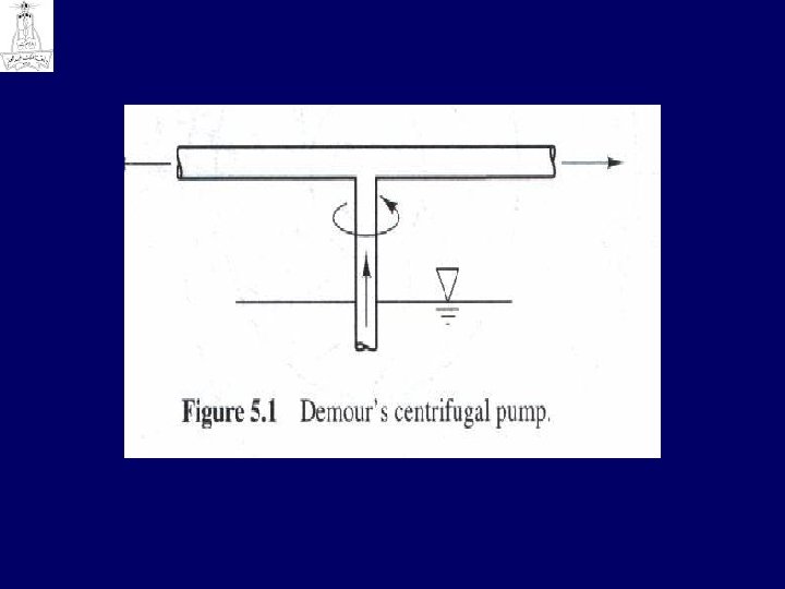
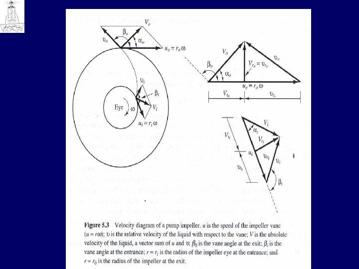
Centrifugal Pumps o Modern centrifugal pumps basically consist of two parts: n 1. the rotating element ( commonly called the impeller); n 2. the housing that encloses the rotating element and seals the pressurized liq uid inside. o The power is supplied by a motor to the shaft of the impeller.
o The rotary motion of the impeller creates a centrifugal force that enables the liquid to enter the pump at the low pressure region near the center (eye} of the impeller and to move along the direction of the impeller vanes toward the higher pressure region near the outside of the housing surrounding the impeller. o The housing is designed with a gradually expanding spiral shape so that the entering liquid is led toward the discharge pipe with minimum loss while the kinetic energy in the liquid is converted into pressure energy.
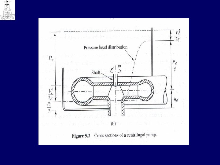
Cross section of a centrifugal pump
5. 3 Jet (Mixed-Flow) Pumps o Jet pumps capitalize on a high pressure stream of fluid. o The pressurized fluid ejects from a nozzle at high speed into a pipeline transferring its energy to the fluid requiring delivery. o Jet pumps are usually used in combination with a centrifugal pump, which supplies the high pressure stream, and can be used to lift liquid in deep wells. o They are usually compact in size and light in weight. o They are sometimes used in construction for dewatering the work site.
o Because the energy loss during the mixing procedure is heavy, the efficiency of the jet pump is normally very low (rarely more than 25%). o A jet pump can also be installed as a booster pump in series with a centrifugal pump. The jet pump may be built into the casing of the centrifugal pump suction line to boost the water surface elevation at the inlet of the centrifugal pump as shown sche matically in Figure 5. 7. This arrangement avoids any unnecessary installation of mov ing parts in the well casing, which is usually buried deep below the ground surface.
Jet (Mixed Flow) Pumps
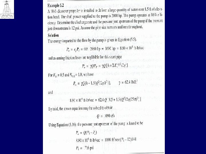
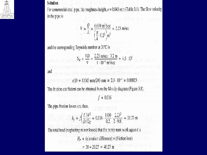
5. 4 Selection of a Pump o The efficiency of a pump depends on: n the discharge, head, and power requirement of the pump. o The approximate ranges of application of each type of pump are indicated in Figure 5. 8. o The total head that the pump delivers its discharge against includes the elevation head and the head losses incurred in the system. o The friction loss and other minor losses in the pipeline depend on: n n the velocity of water in the pipe (Chapter 3), and the total head loss can be related to the discharge rate.
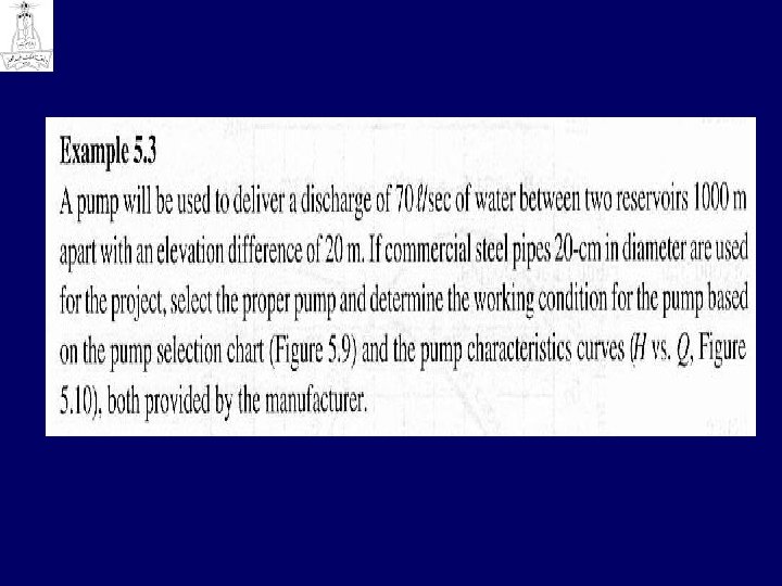
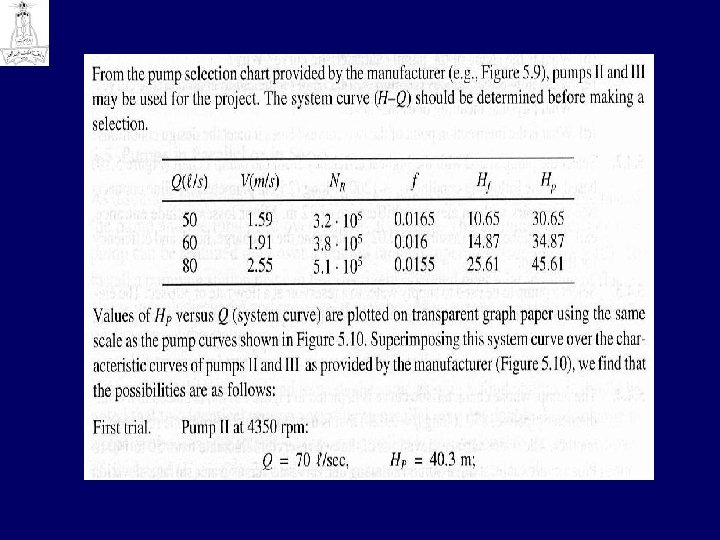
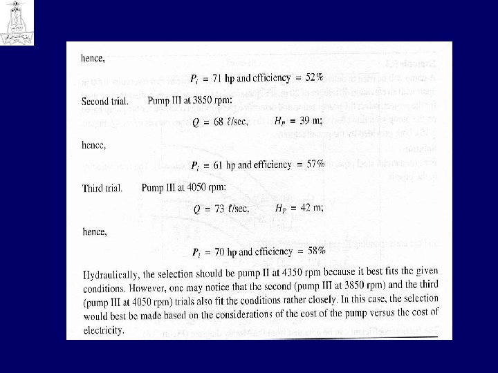
o For a given pipeline system (includ ing the pump), a unique H-Q curve can be plotted, as shown in Example 5. 3, by com puting the head losses for several discharges. o In selecting a particular pump for a given system, the design conditions are specified and a pump is selected for the range of applications. o The H Q curve is then matched to the pump performance chart (e. g. , Fig 5. 9 and 5. 10) provided by the manufacturer. o The matching point , M, indicates the actual working conditions. o Selection process example 5. 3
Selection of a Pump Head, discharge, and power requirement of different pumps
Pump selection Chart
Characteristic curve
Characteristic curve
Characteristic curve
5. 5 Pumps in Parallel or in Series othe efficiency of a pump varies with: n the discharge rate of the pump and n the total head overcome by the pump. o. The optimum efficiency of a pump can be obtained only over a limited range of operation (see Figure 5. 10). o. To install a pumping station that can be effectively operated over a large range of fluctuations in both discharge and pressure, it may be advantageous to install several identical pumps at the station.
o When several pumps are connected in parallel in a pipeline, the discharge is increased but the pressure head remains the same as with a single pump. o It should be noted that two identical pumps operating in parallel may not double the discharge in a pipeline because the total head loss in a pipeline is (Hp a Q 2). o The additional resistance in the pipeline will cause a reduction in the total discharge.
o Curve B in Figure 5. 1 1 schematically shows the operation of two identical pumps in parallel. The joint discharge of the two pumps is always less than twice the discharge of a single pump. o Pumps connected in series in a pipeline will increase the total output pressure, but the discharge will remain approximately the same as that of a single pump. A typical performance curve for two pumps connected in series is shown by curve C in Figure 5. 11.
Pumps in Parallel or Series
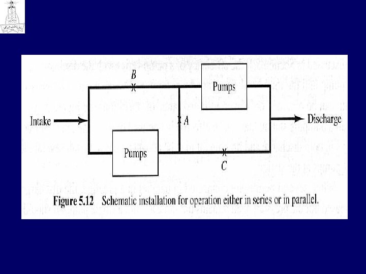
o The efficiency of two (or more) pumps operating in parallel or in series is almost the same as that of the single pump based upon discharge. o The installation can be arranged with a separate motor for each pump or with one motor operating two (or more) pumps. o Multipump installations could be designed to perform either in series or in parallel operations with the same set of pumps. Figure 5. 12 is a typical schematic of such an installation. o For series operations, valve A is opened and valves B and C are closed; for parallel operations, valve A is closed and valves B and C are open.
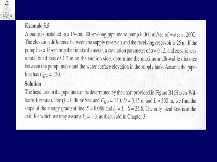
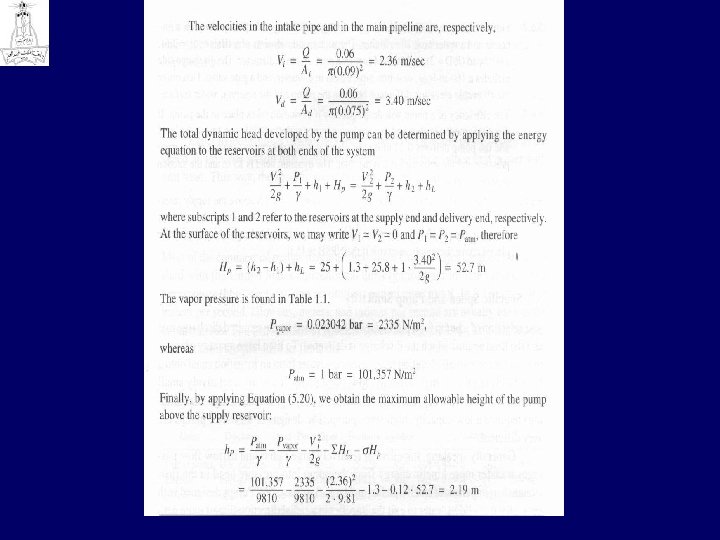
5. 6 Cavitation in Water Pumps o One of the important considerations in pump installation design is the relative elevation between the pump and the water surface in the supply reservoir. o Whenever a pump is positioned above the supply reservoir, the water in the suction line is under pressure lower than atmospheric. The phenomenon of cavitation becomes a potential danger whenever the water pressure at any location in the pumping system drops substantially below atmospheric pressure. o To make matters worse, water enters into the suction line through a strainer that is designed to keep out trash. This additional energy loss at the entrance reduces pressure even further.
o A common site of cavitation is near the tips of the impeller vanes where the velocity is very high. o In regions of high velocities much of the pressure energy is converted to kinetic energy. This is added to the elevation difference between the pump and the supply reservoir, hp, and to the inevitable energy loss in the pipeline between the reservoir and the pump, h. L. Those three items all contribute to the total suction head, Hs, in a pumping installation as shown schematically in Figure 5. 13.
o The value of Hs must be kept within a limit so that the pressure at every location in the pump is always above the vapor pressure of water; otherwise, the water will be vaporized and cavitation will occur. o The vaporized water forms small vapor bubbles in the flow. These bubbles collapse when they reach the region of higher pressure in the pump. Violent vibrations may result from the collapse of vapor bubbles in water. Successive bubble breakup with considerable impact force may cause high local stresses on the metal surface of the vane blades and the housing. These stresses cause surface pitting and will rapidly damage the pump.
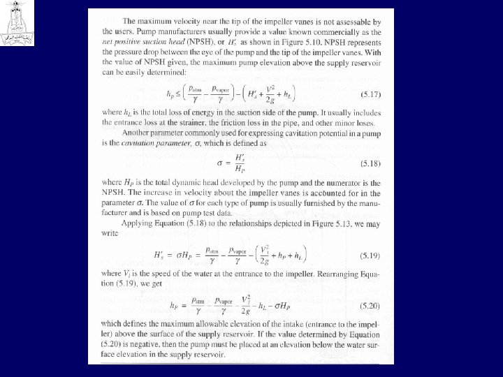
o To prevent cavitation, the pump should be installed at an elevation so that the total suction head is less than the difference between the atmospheric head and the water vapor pressure head, or (Patm/g Pvap/g ) > Hs
Cavitation in Water Pumps
5. 7 Specific Speed and Pump Similarity o The selection of a pump for a particular service is based on the required discharge rate and the head against which the discharge is delivered. o To lift a large quantity of water over a relatively small elevation (e. g. , removing water from an irrigation canal onto a farm field) requires a high capacity, low stage pump. o To pump a relatively small quantity of water against great heights (such as supplying water to a high rise build ing) requires alow capacity, high stage pump. The designs of these two pumps are very different. o Generally speaking, impellers of relatively large radius and narrow flow passages transfer more kinetic energy from the pump into pressure head in the flow stream than impellers of smaller radius and large flow passages. Pumps designed with geometry that allows water to exit the impeller in a radial direction impart more cen trifugal acceleration to the flow than those that allow water to exit axially or at an angle. Thus, the relative geometry of the impeller and the pump housing determine the performance and the field application of a specific pump.
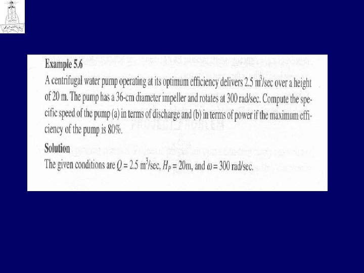
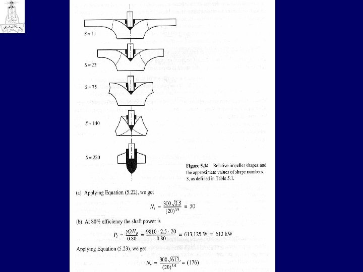
o Dynamic analysis (Chapter 10) shows that centrifugal pumps built with identi cal proportions but different sizes have similar dynamic performance characteristics that are consolidated into one number called a shape number. The shape number of a particular pump design is a dimensionless number defined as o where w is the angular velocity of the impeller in radians per second, Q is the discharge of the pump in cubic meters per second, g is the gravitational acceleration in meters per second squared, and Hp is the total dynamic head in meters that the pump develops.
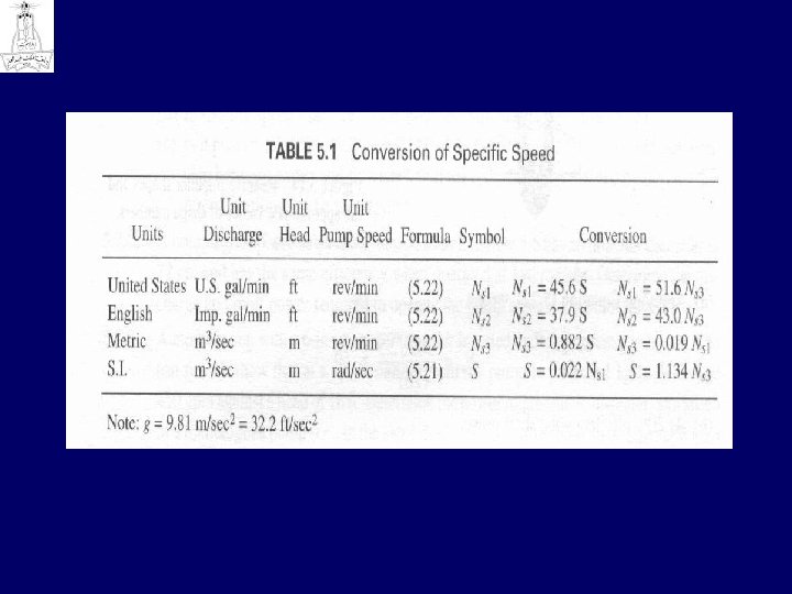
o In engineering practice, however, the dimensionless shape number is not com monly used. Instead, most commercial pumps are specified by the term specific speed. The specific speed of a specific pump design (i. e. , impeller type and geometry) can be defined in two different ways. Some manufacturers define the specific speed o of a specific pump design as the speed an impeller would turn if reduced in size enough to deliver a unit discharge at unit head. This way, the specific speed may be expressed as Eqn (5. 22). o Other manufacturers define the specific speed of a specific pump design as the speed an impeller would turn if reduced enough in size to produce unit power with unit head. This way, the specific speed is expressed as Eqn(5. 23)
o Normally, the specific speed is defined at the optimum point of operational efficiency. o In practice, pumps with high specific speeds are generally used for large discharges at low pressure heads, o while pumps with low specific speeds are used to deliver small discharges at high pressure heads. o Centrifugal pumps with identical geometric proportions but different sizes have the same specific speed. Specific speed varies with impeller type. Its relationship to discharge and pump efficiency is shown in Figure 5. 14.