Wastewater Or Sewage Treatment Purpose of Sewage Treatment

")


 protect moving mechanical equipment from")


- Slides: 18
Wastewater Or Sewage Treatment Purpose of Sewage Treatment: To manage wastewater discharged from homes, businesses, and industries to reduce threat of water pollution. • To remove pollutants from wastewater for its recycling. To promote health concern and public hygiene. More than 50% diseases are spread by untreated sewage due to presence of various pathogens microorganisms , worms etc. To preserve aquatic life and wildlife habitat. • If sewage is disposed untreated in water bodies, it can result in following problems. Depletion of O 2 resources of streams Cause turbidity, colour in water bodies Can be toxic to aquatic life. To promote recreation and quality of life. Sewage is treated to be reused for Irrigation purposes and Ground water recharge
Municipal and Industrial Wastewater Treatment Municipal Wastewater treatment consists of four major categories. (i) Preliminarily treatment (ii) Primary treatment (iii) Secondary treatment and (iv) Advanced treatment. The purpose of pretreatment is to protect the wastewater treatment plant (WWTP) equipment. Primary treatment removes those pollutants that are either settle or float. It remove 50% of suspended solids and 35% BOD. Secondary treatment remove upto 85% suspended solids and BOD. It does not remove nitrogen, phosphorus, or heavy metals significantly, nor completely remove pathogenic bacteria and viruses. When secondary process is not sufficient to fulfilled the treatment requirement then advanced (tertiary) treatment has to be done. It remove 99% BOD, Phosphorus, suspended solids, and bacteria, 95% of nitrogen. It produce clean, colorless odorless water. The impurities removed from wastewater do not vanish simply.
Municipal and Industrial Wastewater Treatment Some of the organics are broken down into harmless CO 2 and water. Most of the impurities are removed from wastewater as a solid, that is sludge. Sludge handling and disposal must also be carried out to achieve satisfactory pollution control. Industrial Wastewater: The municipal WWTP are usually not designed to remove the impurities of industrial waste. The industrial waste can damage the sewer system and /or treatment units. Therefore, a pretreatment process for industrial waste is essential before disposing it in to sanitary sewer and treatment units. The objectives of pretreatment are (i) Prevention of pollutants that interfere the operation of WWTP. (ii) To prevent WWTP of pollutants that will pass without treatment. (iii) To improve opportunities to recycle and reclaim municipal and industrial wastewater and sludge. Such type of industrial waste must not be allowed to sanitary sewer and treatment units. Like Toxic materials, waste that obstruct to flow of sanitary waste; oxygen demanding materials; heated waste of temperature more than 400 C, petroleum oil; or products of mineral oils; toxic gases, vapors etc.
Wastewater Treatment
Water and Wastewater Treatment • Classification of Waste water treatment: • The contaminants present in water / wastewater can be removed by physical, chemical and/or biological means. The individual methods usually classified as physical unit operation, chemical unit processes, and biological unit processes. In some cases there is a combination of these units and processes. • Screening Devices • To operate water and wastewater treatment plants, it is necessary to remove or reduce in early treatment process large suspended solid material that interfere with operations or damaging equipment. The first device used in water and wastewater treatment is known as screening device. • It is also used at the intakes of rivers, lakes and reservoirs for water treatment plants or at well into which main trunk sewer discharges for a wastewater treatment plant. These devices remove large floating materials like old clothes, dead animals,
Screening Devices lumber, tree branches, roots, bushes, plastics etc. As these particles can clog and damage pumping units or impede the hydraulic flow in open channels or pipe network. The removal of these impurities are essential to minimize losses of pumping plant as well as disturbing of flow in channels and pipes. The materials removed by these devices are termed as Screening. The screening are usually non biodegradable materials and can be used for land filling purposes. • Screens or Bar Rack: Screens are classified as coarse screen 50 -150 mm; medium with 25 -50 mm; and fine with less than 20 mm openings. The screen materials are usually made up of stainless steel, milled bronze, or copper, polyester and other fabric screen cloths. The fine screens remove influent suspended solids, Putrescible matter, grease and scum as well as pathogenic fecal materials. To prevent the settling of coarse materials in the channel, the velocity in approach channel must be in the range of 0. 3 m/s to 0. 6 m/s. It consists of parallel bars, rods or wires, grating, wire mesh or perforated plate, having opening of any shape but circular and rectangular are common.
Head losses in Screen and Bar rack •
Comminutor • Located across the flow path and intercepts the coarse solids and shred them to approximately 8 mm in size. It consists of a screen and cutting teeth. It need frequently proper maintenance and provisions should be made to by-pass flow during repairs. Small plants use screens as by-pass while large plants install comminutor in parallel.
Grit Chamber • l Grit are small inorganic solids like pebbles, sand, silt, eggshells, glass and metal fragment. As Grits are abrasive in nature and will cause wear on pumps. Grit deposits in pipes, sumps and clarifiers can absorb grease and solidify. They are non biodegradable and occupy valuable space in the digest. The major contributor is infiltration and depends on the type, age and condition of sewerage systems Industrial waste and Domestic garbage also contribute grit materials. Therefore its removal is essential. Usually grit particles are inert and dry, however 15 to 65% moisture content are present depend on the nature of grit. Inorganic particles with Sp. gravity ≥ 2. 65 and approximate diameter of 0. 20 mm or larger can be removed. while organic matters be keep in suspension. The physical operation to remove is termed as Grit Chamber.
Grit Chamber • Grit chamber are provided to (i) protect moving mechanical equipment from abrasion and abnormal wear (ii) Reduce formation of heavy deposits in pipelines (iii) Reduce the frequency of digester cleaning caused by excessive accumulation of grit and (iv) To separate inorganic particles from organic and disposed off of these particles just to wash without passing any further treatment process. • Grit Chambers are usually located after bar racks and before sedimentation tanks. Similarly, the installation of screening facilities ahead of the grit chambers make the operation and maintenance of grit removal easier. • Two important types of Grit Chambers (i) Horizontal flow Rectangular and (ii) Aerated Grit Chamber
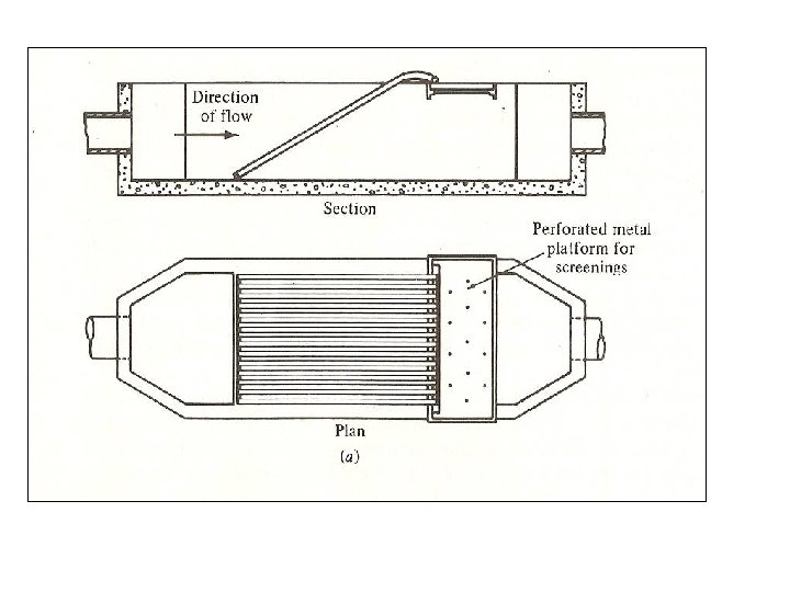
Types of Grit Chambers Rectangular Horizontal-flow grit chamber: The unit is designed to maintain a velocity of 0. 3 m/s and to provide sufficient time for grit particles to settle at channel while organic particles are kept in suspension. A 25% increase in velocity may result in washout of grit, while 25% reduction result retention of non-target organics. The design of horizontal flow grit chamber be such that, the lightest particles of grit will reach the bed of the channel. Usually grit chambers must be designed to remove particles of diameter of 0. 20 mm. The length of channel will be based on the settling velocity and control section, while cross section area will be based on the rate of flow and the number of channels. Allowance should be made for inlet and outlet turbulence. The grit removal from horizontal chamber is accomplished by a conveyor with scraper and buckets. In small units it is cleaned manually.
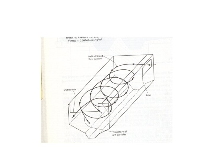
Types of Grit Chambers Typical Design information for horizontal flow grit chambers Item Detention time (sec) Horizontal Velocity (m/s) settling velocity (m/s) Range Typical value 45 - 90 60 0. 244 – 0. 40 0. 30 1. 0 – 1. 30 1. 15 • Aerated Grit Chamber: Aerated Grit chambers are normally designed to remove particles of size 0. 20 mm or larger with 2 to 5 minute detention time at peak hour flow. This type of chamber may serve another useful purpose, if the sewage is anaerobic when it arrives at the plant, aeration serves to strip noxious gases from the liquid and to restore it immediately to an aerobic condition, which allows for better treatment. Influent and effluent baffles are used frequently for hydraulic control and improved grit removal effectiveness. The diffusers are located about 0. 45 to 0. 60 meters above the normal plane of the bottom.
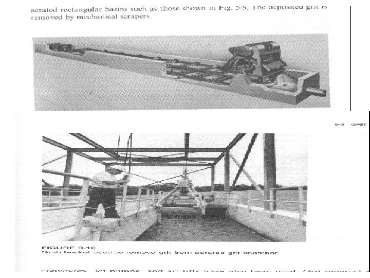
Aerated Grit Chambers With proper adjustment 100% removal will be obtained, and the grit will be well washed. Wastewater will move through the tank in a spiral path and will make two to three passes across the bottom of the tank. For grit removal, aerated grit chambers are often provided with grab buckets traveling on monorails and centered over the grit and storage trough. Bucket removal of grit can be further washed by dropping the grit from bucket through the tank contents. In case of industrial wastewater is discharged having VOCs then either covering of system is required of other type of grit removal will be used. Design parameter for aerated grit chamber item Range Dimensions Depth X length X width (m) 2. 5 X (7. 5 – 20) X (2. 5 – 7. 0) Width depth ratio 1: 1 to 5: 1 Detention time at peak flow (min) 2 – 5 Air supply (m 3/min. m of length) 0. 15 – 0. 45 Grit and scum quantities (m 3/ 103 m 3 0. 004 – 0. 200 Typical value 2: 1 3 0. 015
Grit Chamber Example • Design an aerated Grit Chamber for the treatment of Municipal waste water. The average wastewater flow is 0. 5 m 3/sec, and the peak flow factor is 2. 7 times of average flow. Use two tanks calculate the grit chamber volume and grit materials if 0. 05 m 3/103 m 3 of peak flow is the grit concentration. Assume the average detention time is 180 seconds and horizontal velocity 0. 25 m/sec, while settling velocity is 0. 03 m/sec. Also calculate volume of air supply if the rate is 0. 3 m 3/minute-m length of chamber. Assume W: D is 1. 2: 1, while depth is 3 m. • Volume of grit chamber = 0. 5 *2. 7 * 3 minute * 60 secs = 248. 4 m 3 for one unit volume = 124. 2 m 3 •
Grit Chamber Example • Given Information: Q average = 0. 5 m 3/sec; Peak flow Factor = 2. 7; no of tanks = 2; Volume of grit materials = 0. 05 m 3/(103 m 3); Vh = 0. 25 m/s Vs = 0. 03 m/sec; td= 180 secs Q air = 0. 3 m 3/ (minute- m) W ; D = 1. 2 : 1 and D = 3 m • Required: Dimensions; Air Supply and Grit materials • • Solution: Peak flow = 0. 5 *2. 70 = 1. 35 m 3/sec Volume of tank = Q * t – 1. 35 m 3/sec * 180 secs = 243 m 3 Volume of one tank = 121. 5 m 3 Volume = L * W * D where W : D = 1. 2 : 1 and D = 3. 0 m so W = 3. 6 m V = 121. 5 = L * 3. 0 * 3. 6 or L = 121. 5/(3*3. 6) = 11. 25 m The dimensions are L = 11. 25 m ; W = 3. 6 m and D = 3. 0 m Answer Air Supply = 0. 3 m 3/ (minute-m) * 11. 25 * 180/60 = 10. 125 m 3 Answer Grit materials = 0. 05 m 3/103 m 3 of flow = (0. 05 m 3/103 m 3 )(1. 35 * 3600 *24 = 5. 832 m 3/day Answer