WAGON 801 CLASSIFICATION OF AIR BRAKE SYSTEM On

WAGON 801. CLASSIFICATION OF AIR BRAKE SYSTEM On the basis of type of release, air brake system is classified as: Direct release air brake system Graduated release air brake system Both Direct and Graduated release are further available in two forms viz. Single pipe and Twin pipe

WAGON Oxford Learners Dictionary • Definition: • A railway /railroad truck for carrying goods. • Vehicle with 4 wheels pulled by horses or oxen and used for carrying heavy loads. • Wagon(Informal)To not drink alcohol, either for short time or permanently.
 Distributor valve ii)")
Air brake system consist of following components: • • • i) Distributor valve ii) Common pipe bracket with control reservoir. iii) Aux-il-iary reservoir. (100 Litres) iv) Three way centrifugal dirt collector. v) Isolating cock. vi) Brake cylinder (355 mm diameter). vii) Cut off angle cock (32 mm size on either ends of brake pipe). viii) Air brake hose coupling (32 mm for brake pipe). . ix) Brake pipe (32 mm dia). x) Branch pipes from BP to brake equipment (20 mm bore). xi) Guard emergency brake valve. xii) Pressure gauges for BP

Graduated released single pipe air brake system

Charging Stage

Application Stage

• For application of brakes, the pressure in brake pipe has to be dropped. This is done by venting air from driver’s brake valve. Reduction in brake pipe pressure positions the distributor valve in such a way that the control reservoir gets disconnected from brake pipe and auxiliary reservoir gets connected to brake cylinder. This results in increase in air pressure in brake cylinder resulting in application of brakes. The magnitude of braking force is proportional to reduction in brake pipe pressure • Note: 1. Brake Application takes places when Brake pipe pressure is dropped. • 2. The drop of pressure may be a) Intentional and b) Accidental.

Release stage

COMMON PIPE BRACKET • Common pipe bracket is permanently mounted on the under frame of a vehicle. • The Common pipe bracket has been evolved with the purpose of making it • suitable for use with any make of distributor valve adopted on Indian Railways. • Common pipe bracket is a sturdy casting with internal air passages, matching the • intermediate piece mounting face with accurately profiled air cavities and flanged ports • leading to the appropriate ports of the distributor valve. • Branch pipes to the brake pipe and brake cylinders are fitted on the appropriate • ports on the common pipe bracket.

BRAKE PIPE HOSES

BRAKE PIPE COUPLING • To connect subsequent wagons, the hoses of BP are screwed to coupling and • hose nipple by means of stainless steel `Bend it’ type clips. • The air brake hose couplings are provided in the brake pipe line throughout the • train for connecting the brake pipe of adjacent wagons to form the complete rake.

Testing of Hose Coupling

Test procedure-Safety precautions • SAFETY PRECAUTIONS • Specified tools and fixtures should be used for connecting and disconnecting the hose coupling with the air supply. • While testing the hose coupling before charging it to 10 kg/cm 2 pressure, the tube should be covered and locked with a protective cage. • Exhaust the pressure from the hose coupling under test, before lifting the safety cage and uncoupling it. • After testing, the hose assembly shall be stored in a dry and clean space. The inlet and outlet port must be plugged with protective cap to prevent entry of dust and foreign particles inside the hose coupling.

CUT OFF ANGLE COCK • • Cut off angle cocks are provided on the air brake system to facilitate coupling and uncoupling of air hoses (i. e. brake pipe). When the handle of the cut off angle cock is placed in closed position it cuts off the passage of compressed air, there by facilitating coupling and uncoupling action.

BRAKE CYLINDER • • On every wagon fitted with air brake system one brake cylinder is provided for actuating the brake rigging for the application and release of brakes.

• FUNCTION OF DIRT COLLECTOR Dirt Collector is placed in the brake pipe line at a point from where a branch is taken off to the distributor valve. As the name indicates the purpose of the dirt collectoris to protect the distributor valve and the auxiliary reservoir by trapping dust and other foreign matters from the compressed air before it enters into the distributor valve and the auxiliary reservoir. This action is achieved by centrifugal action. Hence it is also known as centrifugal dirt collector. The dirt collector ensures inter vehicular full flow of dirt free compressed air to the auxiliary reservoir and the distributor valve through the branch pipes. When the air enters into the body of the dirt collector tangentially through port `A’ it passes down through inverted case in a spiral path. Due to the velocity of air flow, dirt particles get flung outwards. There after they slide down & collect at the bottom.

SAFETY PRECAUTIONS Dirt Collections • • The assembled dirt collector should be stored in such a way to prevent the following: Flange surface should be prevented from damage. Inlet and outlet port should be plugged with protective caps to prevent the entry of moisture and dirt inside the dirt collector. Specified tools and fixtures should be used for handling, mounting and removing the dirt collector from the test bench. The small metal parts like screws, nuts, bolts, washers etc. should be kept in a safe place and replaced in case found defective,

AUXILIARY RESERVOIR FUNCTION • Auxiliary reservoir is actually a pressure vessel and its function is to feed dry compressed air to the brake cylinder for application of brakes. • B. SALIENT FEATURES • The auxiliary reservoir is a cylindrical vessel made of sheet metal.

811. GUARD'S EMERGENCY BRAKE VALVE • Guard's emergency brake valve is provided in the guard ‘s compartment. This valve provides a facility to the guard to initiate brake application in case of any emergency. • SALIENT FEATURES • The guard’s emergency brake valve consists of a housing in which a ball is housed.

QUICK COUPLING ARRANGEMENT For fitment of gauge an arrangement for quick coupling is provided. The figure showing the arrnagement. The quick coupling when assembled with and without plug shall be leakproof when tested upto 10 kg/cm 2 air pressure.
 is a")
SLACK ADJUSTER SALIENT FEATURES • Slack adjuster (also known as brake regulator) is a device provided in the brake rigging for automatic adjustment of clearance/slack between brake blocks and wheel. It is fitted into the brake rigging as a part of mechanical pull rod.

DISTRIBUTOR VALVE • Distributor valve is the most important functional component of the air brake system and is also sometimes referred to as the heart. The function of the distributor valve is to distribute compressed air received from brake pipe to auxiliary reservoir and control reservoire air brake system.

FUNCTION OF DISTRIBUTOR VALVE • • • • • For application and release of brakes the brake pipe pressure has to be reduced and increased respectively with the help of driver's brake valve. During these operations the distributor valve mainly performs the following function. (i) Charges the air brake system to regime pressure during normal running condition. (ii) Helps in graduated brake application, when pressure in brake pipe is reduced in steps. (iii) Helps in graduated brake release, when pressure in brake pipe is increased in steps. (iv) Quickly propagates reduction of pressure in brake pipe throughout the length of the train by arranging additional air pressure reduction locally inside the distributor valve. (v) Limits maximum brake cylinder pressure for full service application/ emergency application. (vi) Controls the time for brake application and brake release depending on service conditions (vii) Facilitates complete discharge of air from the air brake system manually with the help of operating lever. (viii) Protects overcharging of control reservoir when the brake pipe pressure is quickly increased for releasing the brakes.

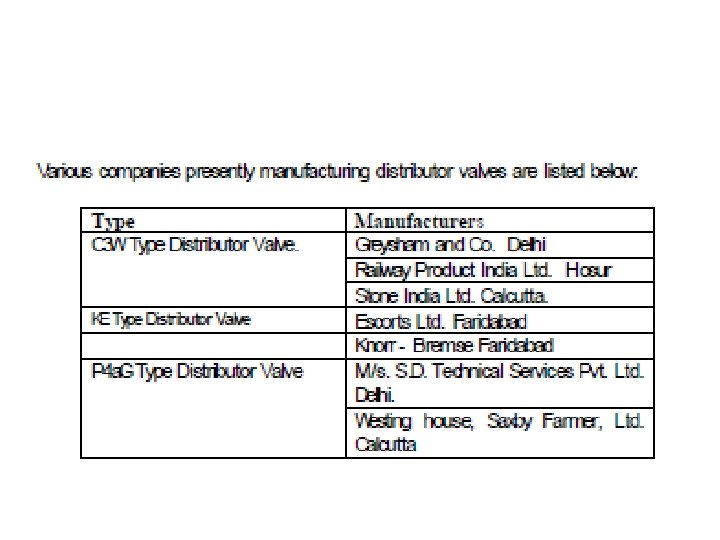
C 3 W DISTRIBUTOR VALVE

D. DIFFERENT STAGES IN OPERATION OF C 3 W ISTRIBUTOR VALVE • For effective functioning of the air brake system, the distributor valve has to operate effectively during : • a) Charging stage • b) Application stage and • c) Release stage

• RELEASE STAGE • When the brake pipe pressure is increased in steps for graduated release

MAINTENANCE OF BRAKE ASSEMBLY • Dismantling and cleaning assembling and testing storage of assembled distributor valve & storage of spare parts including POH kits stocking store etc.
 Pressure Tightness Test b)")
PURPOSE OF CONDUCTING VARIOUS TESTS • • • • a) Pressure Tightness Test b) Charging Time c) Full Service Application and Release. d) Overcharge Protection e) CR Overcharge Reduction Test f) Emergency Application Test g) Sensitivity Test h) Quick Service Test i) Insensitivity Test j) Re-feeding Test k) Graduated Application Test l) Graduated Release Test m) Quick Release Test n) CR Check Valve Reset Test

CHOKE COVER The choke cover has application & release chokes inside it. The application and release chokes help in regulating the application and release times of brake.

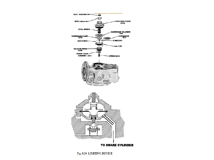
MINIMUM PRESSURE LIMITER The minimum pressure limiter gets activated during initiation of brake application. The minimum pressure limiter helps in rapid charging of brake cylinder upto a determined pressure to overcome rigging resistance.

A-CONTROLLER Besides charging control reservoir during charging operation 'A' controller isolates control reservoir pressure when brakes are applied. 'A' controller also protects control reservoir from overcharging.

QUICK RELEASE VALVE • The quick release valve allows the brakes of the wagons to be fully released by means of manually pulling of handle. • For effective functioning of the air brake system, the KEGisl distributor valve has to operate effectively during : • Charging stage • Application stage and • Release stage

QUICK RELEASE VALVE

SINGLE WAGON TEST • ‘Single wagon Test’ is performed on a wagon to ensure proper functioning of the air brake system. It is generally performed on the sick wagon attended in the sick line or whenever a subassembly of the air brake system is replaced either in depot or workshop. • Single wagon test is also carried out after POH and after every change of distributor valve in the workshop.
 is shown in")
RAKE TEST • A schematic layout of rake test rig (RTR) is shown in Fig. 8. 34. A rake consisting of 56 wagons can be tested with this rig. This rig may be used for testing the train in yard before attaching the engine. • The rake test rig has air supply and mobile test rig. The mobile test rig is having a cubical structure and is mounted on wheels. It can be taken to the yards and sick lines. The procedure is as follows: • A. Carry out Visual Examination. • B. Prepare set up (Rig) for Rake Test. • C. Conduct Leakage, Service Application and Release Test.

BRAKE POWER CALCULATIONS FOR BOXN WAGON • • • TYPE OF BRAKE SYSTEM = AIR BRAKE CYLINDER DIA = 355 mm NO OF CYLINDERS = ONE TOTAL EFFECTIVE PISTON FORCE = 3600 Kg (K)AFTER SUBTRACTION OF RESTORING SPRING FORCE AT A STORKE OF 135 mm LEVERAGE EMPTY = 335 x 12 =6. 5 620 LOADED= 458 x 12 =11. 05 497

Hand Brake
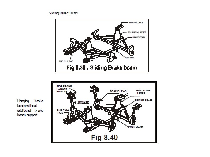
 Brake beam")
CASNUB 22 W (M) Brake beam
- Slides: 42