VOR VHF Omnidirectional Range With the help of


 radial.")


")
")


 CARRIER ANTENNA 1 30 Hz 2 MONITOR ANTENNA")
 30 Hz VAR PHASE COMP LPF")
 Frequency Range :")
- Slides: 23
VOR VHF Omnidirectional Range With the help of CAAP navaids ANS staffs davao branch
WHAT IS VOR? VOR or VHF Omnidirectional Range is a navigational aid equipment designed to provide bearing information to aircraft.
WHAT IS BEARING? Bearing refers to the direction from a certain place towards another. In VOR application, this refers to the bearing from an airplane to a VOR station.
The VOR System
ALL DIRECTIONS ASSOCIATED WITH A VOR STATION ARE RELATED TO MAGNETIC NORTH. These are shown in the figures below:
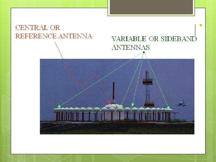
How is the bearing information produced by the VOR ? This is done by radiating two signals from two sets of antenna, the central or reference antenna and the variable or sideband antennas surrounding the central antenna.
The phase of the signal received from the reference or central antenna is the same regardless of aircraft position. N 0° 30° 60° 90° 180° 210° 240° 270° 300° 120° 150° 330° 360°
However, the signal received from the sideband or variable antennas depend on the aircraft’s position. N 0° 30° 60° 90° 180° 210° 240° 270° 300° 120° 150° 330° 360°
The aircraft’s VOR receiver then processes these two signals to obtain its angular position with respect to magnetic north. N 0° 30° 60° 90° 180° 210° 240° 270° 300° 120° 150° 330° 360°
The phasethe difference Supposed aircraft is between signals in the eastthe (ortwo 90°) radial. would then be: 90 degrees 0° 30° 60° 90° 180° 210° 240° 270° 300° 120° 150° 330° 360° 90 N
In practice the aircraft’s VOR receiver has three dials: • one of which can be set manually to any desired course, • the second of which tells whether the plane is to the left or right of the course, and • the third of which resolves 180° ambiguity by indicating either “from” or “to”.
Tells whether the airplane is to the LEFT or RIGHT of desired course Indicates desired course “TO or “FROM” ARROW 0 1 5 COURSE 33 N 3 12 24 E W 30 6 15 S 21
VOR Deviation - “Left” Or “Right” Sense (Selected Course 90 )
VOR “TO” or “FROM” Sense (Selected Course 90 )
c 0 CO N UR 0 a 0 SE 33 3 6 30 b N S 21 Selected Course - 000 (N) 15 a 12 24 E W VOR
c b N 0 0 0 COU R SE 33 3 6 30 b N S 21 Selected Course - 000 (N) 15 a 12 24 E W VOR
c c N 0 0 0 COURSE 33 N 3 6 30 b 24 12 S 21 Selected Course - 000 (N) 15 a E W VOR
0 A 113. 9 MHz 27 An aircraft may pass These VOR stations radiate through several VOR at different frequencies. stations in travelling from one place to another (Point A to B). 9 18 0 115. 1 MHz 27 9 0 18 N 0 112. 7 MHz 27 9 18 B 116. 3 MHz 27 9 18
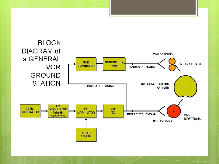
SIDEBAND ANTENNAS ( X 48 ) CARRIER ANTENNA 1 30 Hz 2 MONITOR ANTENNA 48 OUTDOOR INDOOR DISTRIBUTOR UNIT MONITOR RECEIVER ANTENNA CHANGEOVER UNIT MONITOR 1 AFC CARRIER POWER AMP MODULE (fo) ALC UPPER SIDEBAND MODULE (fo + 9960 Hz) 30 Hz (REF) 1020 Hz (ID) LOWER SIDEBAND MODULE (fo - 9960 Hz) MONITOR 2 CONTROL UNIT MONITOR & CONTROL UNIT 9960 Hz 720 Hz (SIN) 720 Hz (COS) MOD SIG GEN Module TRANSMITTER UNIT Simplified Block Diagram of DVOR
Block Diagram of a VOR Receiver ( Airborne) 30 Hz VAR PHASE COMP LPF O O O TO RF IF OBS 0 -360° AM DET OBS LO CDI 9960 Hz filter FM DET LPF 30 Hz REF
The DVOR Training Equipment Specification: Model : TW 2158 A (Toshiba) Frequency Range : 108 -118 Mhz Modulating Freq. : 30 Hz Identification Freq. : 1020 Hz