VOLTAGE SOURCE CONVERTER BASED FACTS CONTROLLERS Static Synchronous

VOLTAGE SOURCE CONVERTER BASED FACTS CONTROLLERS
 • The STATCOM (or SSC) is a shunt connected reactive")
Static Synchronous Compensator (STATCOM) • The STATCOM (or SSC) is a shunt connected reactive power compensation device that is capable of generating and/ or absorbing reactive power and in which the output can be varied to control the specific parameters of an electric power system. • It is in general a solid state switching converter capable of generating or absorbing independently controllable real and reactive power at its output terminals when it is fed from an energy source or energy storage device at its input terminals.

STATCOM • STATCOM considered as a voltage source converter that produces a set of 3 phase ac output voltages from a given input of dc voltage, each in phase with and coupled to the corresponding ac system voltage through a relatively small reactance (which is provided by either an interface reactor or the leakage inductance of a coupling transformer). • The dc voltage is provided by an energy storage capacitor.

STATCOM A STATCOM can improve power system performance in such areas as the following: 1. The dynamic voltage control in transmission and distribution systems; 2. the power oscillation damping in power transmission systems; 3. the transient stability; 4. the voltage flicker control; and 5. the control of not only reactive power but also (if needed) active power in the connected line, requiring a dc energy source. Furthermore, a STATCOM does the following: 1. it occupies a small footprint, for it replaces passive banks of circuit elements by compact electronic converters; 2. it offers modular, factory built equipment, thereby reducing site work and commissioning time; and 3. it uses encapsulated electronic converters, thereby minimizing its environmental impact.

STATCOM • A STATCOM is analogous to an ideal synchronous machine, which generates a balanced set of three sinusoidal voltages—at the fundamental frequency—with controllable amplitude and phase angle. • This ideal machine has no inertia, is practically instantaneous, does not significantly alter the existing system impedance, and can internally generate reactive (both capacitive and inductive) power. • STATCOM controller provides voltage support by generating or absorbing reactive power at the point of common coupling without the need of large external reactors or capacitor banks.

The Principle of Operation of STATCOM • A STATCOM is a controlled reactive power source. It provides the desired reactive power generation and absorption entirely by means of electronic processing of the voltage and current waveforms in a voltage source converter (VSC).
,")
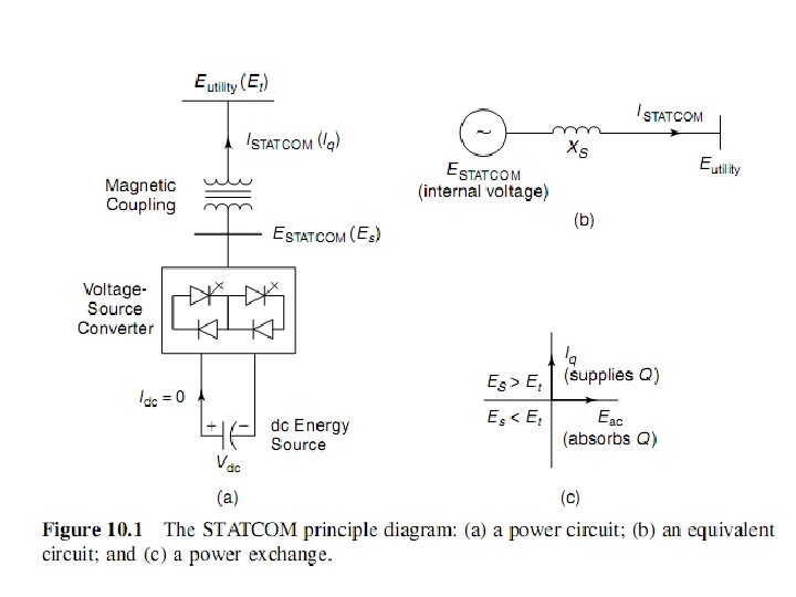
• A single line STATCOM power circuit is shown in Fig. 10. 1(a), where a VSC is connected to a utility bus through magnetic coupling. • In Fig. 10. 1(b), a STATCOM is seen as an adjustable voltage source behind a reactance—meaning that capacitor banks and shunt reactors are not needed for reactive power generation and absorption, thereby giving a STATCOM a compact design, or small footprint, as well as low noise and low magnetic impact. • The exchange of reactive power between the converter and the ac system can be controlled by varying the amplitude of the 3 phase output voltage, ES, of the converter, as illustrated in Fig. 10. 1(c).

• if the amplitude of the output voltage is increased above that of the utility bus voltage, Et, then a current flows through the reactance from the converter to the ac system and the converter generates capacitive reactive power for the ac system. • If the amplitude of the output voltage is decreased below the utility bus voltage, then the current flows from the ac system to the converter and the converter absorbs inductive reactive power from the ac system. • If the output voltage equals the ac system voltage, the reactive power exchange becomes zero, in which case the STATCOM is said to be in a floating state.

• Adjusting the phase shift between the converter output voltage and the ac system voltage can similarly control real power exchange between the converter and the ac system. • the converter can supply real power to the ac system from its dc energy storage if the converter output voltage is made to lead the ac system voltage. • it can absorb real power from the ac system for the dc system if its voltage lags behind the ac system voltage.

• A STATCOM provides the desired reactive power by exchanging the instantaneous reactive power among the phases of the ac system. The mechanism by which the converter internally generates and/ or absorbs the reactive power can be understood by considering the relationship between the output and input powers of the converter. • The converter switches connect the dc input circuit directly to the ac output circuit. Thus the net instantaneous power at the ac output terminals must always be equal to the net instantaneous power at the dc input terminals (neglecting losses)

• Assume that the converter is operated to supply reactive output power. In this case, the real power provided by the dc source as input to the converter must be zero. • Furthermore, because the reactive power at zero frequency (dc) is by definition zero, the dc source supplies no reactive power as input to the converter and thus clearly plays no part in the generation of reactive output power by the converter. • In other words, the converter simply interconnects the three output terminals so that the reactive output currents can flow freely among them. • If the terminals of the ac system are regarded in this context, the converter establishes a circulating reactive power exchange among the phases.

• However, the real power that the converter exchanges at its ac terminals with the ac system must, of course, be supplied to or absorbed from its dc terminals by the dc capacitor. • Although reactive power is generated internally by the action of converter switches, a dc capacitor must still be connected across the input terminals of the converter. • The primary need for the capacitor is to provide a circulating current path as well as a voltage source. • The magnitude of the capacitor is chosen so that the dc voltage across its terminals remains fairly constant to prevent it from contributing to the ripples in the dc current. • The VSC output voltage is in the form of a staircase wave into which smooth sinusoidal current from the ac system is drawn, resulting in slight fluctuations in the output power of the converter.

• However, to not violate the instantaneous power equality constraint at its input and output terminals, the converter must draw a fluctuating current from its dc source. • Depending on the converter configuration employed, it is possible to calculate the minimum capacitance required to meet the system requirements, such as ripple limits on the dc voltage and the rated reactive power support needed by the ac system. • The VSC has the same rated current capability when it operates with the capacitive or inductive reactive current. Therefore, a VSC having a certain MVA rating gives the STATCOM twice the dynamic range in MVAR (this also contributes to a compact design). • A dc capacitor bank is used to support (stabilize) the controlled dc voltage needed for the operation of the VSC.

• The reactive power of a STATCOM is produced by means of power electronic equipment of the voltage source converter type. • The VSC may be a 2 level or 3 level type, depending on the required output power and voltage. A number of VSCs are combined in a multi pulse connection to form the STATCOM. • In the steady state, the VSCs operate with fundamental frequency switching to minimize converter losses. • However, during transient conditions caused by line faults, a pulse width–modulated (PWM) mode is used to prevent the fault current from entering the VSCs. • In this way, the STATCOM is able to withstand transients on the ac side without blocking.

The V-I Characteristic

The V-I Characteristic • A typical V I characteristic of a STATCOM is depicted in Fig. the STATCOM can supply both the capacitive and the inductive compensation and is able to independently control its output current over the rated maximum capacitive or inductive range irrespective of the amount of ac system voltage. • the STATCOM can provide full capacitive reactive power at any system voltage—even as low as 0. 15 p. u. • The characteristic of a STATCOM reveals another strength of this technology: that it is capable of yielding the full output of capacitive generation almost independently of the system voltage (constant current output at lower voltages). • This capability is particularly useful for situations in which the STATCOM is needed to support the system voltage during and after faults where voltage collapse would otherwise be a limiting factor.

• Figure 10. 2 also illustrates that the STATCOM has an increased transient rating in both the capacitive and the inductive operating regions. • The maximum attainable transient overcurrent in the capacitive region is determined by the maximum current turn off capability of the converter switches. • In the inductive region, the converter switches are naturally commutated; therefore, the transient current rating of the STATCOM is limited by the maximum allowable junction temperature of the converter switches.

• In practice, the semiconductor switches of the converter are not lossless, so the energy stored in the dc capacitor is eventually used to meet the internal losses of the converter, and the dc capacitor voltage diminishes. • However, when the STATCOM is used for reactive power generation, the converter itself can keep the capacitor charged to the required voltage level. • This task is accomplished by making the output voltages of the converter lag behind the ac system voltages by a small angle (usually in the 0. 1 O– 0. 2 O range). • In this way, the converter absorbs a small amount of real power from the ac system to meet its internal losses and keep the capacitor voltage at the desired level. • The same mechanism can be used to increase or decrease the capacitor voltage and thus, the amplitude of the converter output voltage to control the var generation or absorption.

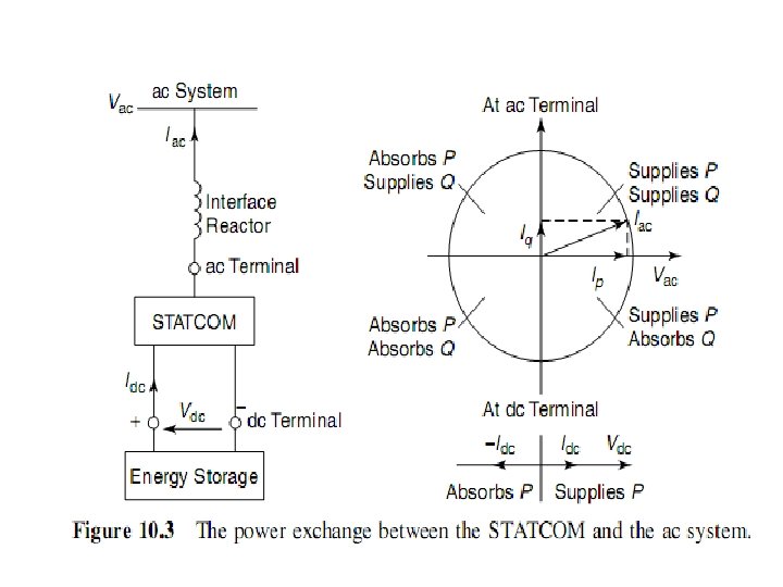
• The reactive and real power exchange between the STATCOM and the ac system can be controlled independently of each other. • Any combination of real power generation or absorption with var generation or absorption is achievable if the STATCOM is equipped with an energy storage device of suitable capacity, as depicted in Fig. 10. 3. • With this capability, extremely effective control strategies for the modulation of reactive and real output power can be devised to improve the transient and dynamic system stability limits.

 • The SSSC, sometimes called the S 3 C,")
Static Series Synchronous Compensator (SSSC) • The SSSC, sometimes called the S 3 C, is a series connected synchronous voltage source that can vary the effective impedance of a transmission line by injecting a voltage containing an appropriate phase angle in relation to the line current. • It has the capability of exchanging both real and reactive power with the transmission system. • For instance, if the injected voltage is in phase with the line current, then the voltage would exchange real power. • On the other hand, if a voltage is injected in quadrature with the line current, then reactive power—either absorbed or generated—would be exchanged. • The SSSC emerges as a potentially more beneficial controller than the TCSC because of its ability to not only modulate the line reactance but also the line resistance in consonance with the power swings, thereby imparting enhanced damping to the generators that contribute to the power oscillations.

• The SSSC comprises a multi phase VSC with a dc energy storage controller, as shown in Fig. 10. 18(a). Here, the controller is connected in series with the transmission line. The operating modes of the SSSC are illustrated graphically in Fig. 10. 18(b).

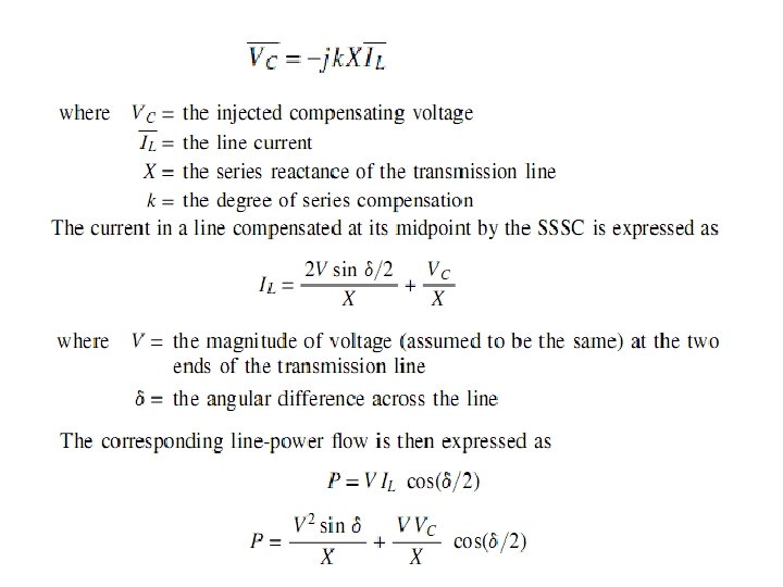
The Principle of Operation • A series capacitor compensates the transmission line inductance by presenting a lagging quadrature voltage with respect to the transmission line current. • This voltage acts in opposition to the leading quadrature voltage appearing across the transmission line inductance, which has a net effect of reducing the line inductance. • Similar is the operation of an SSSC that also injects a quadrature voltage, VC, in proportion to the line current but is lagging in phase:

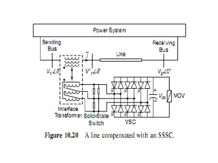
• A series compensation scheme using the SSSC is depicted in Fig. 10. 19. Normally, the SSSC output voltage lags behind the line current by 90 O to provide effective series compensation. • In addition, the SSSC can be gated to produce an output voltage that leads the line current by 90 O, which provides additional inductive reactance in the line. • This feature can be used for damping power swings and, if the converter has adequate rating, for limiting short circuit currents. • A typical SSSC controller connected in a transmission line is shown in Fig. 10. 20. This controller comprises a VSC in which its coupling transformer

A typical SSSC controller connected in a transmission line is shown in Fig. 10. 20.

• This controller comprises a VSC in which its coupling transformer is connected in series with the transmission line. • The valve side voltage rating is higher than the line side voltage rating of the coupling transformer to reduce the required current rating of the gate turn off (GTO) thyristor valves. • The valve side winding is delta connected to provide a path for 3 rd harmonics to flow. Solid state switches are provided on the valve side to bypass the VSC during periods of very large current flow in the transmission line or when the VSC is inoperative. • The basic dc voltage for conversion to ac is provided by the capacitor, and the dc/ ac conversion is achieved by pulse width–modulation techniques. • The dc capacitor rating is chosen to minimize the ripple in the dc voltage. An MOV is installed across the dc capacitor to limit its voltage and provide protection to the valves.

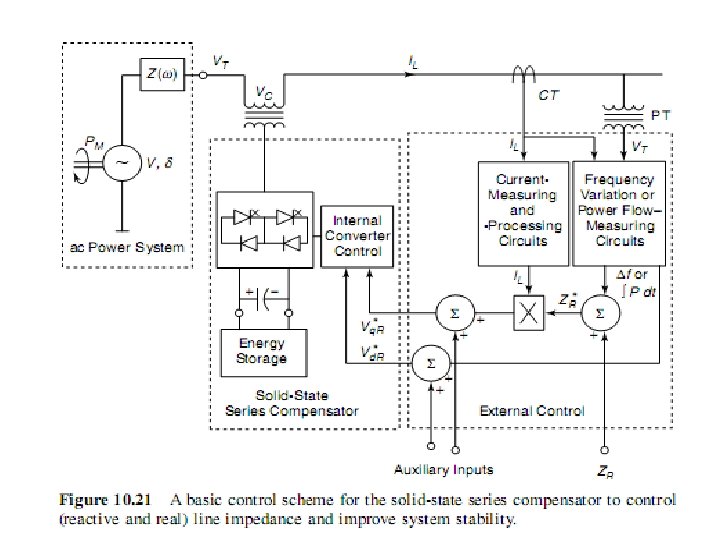
The Control System • A typical SSSC control system is depicted in Fig. It accomplishes the following functions: 1. The introduction of desired series reactive compensation (capacitive or inductive). 2. The damping of power swing oscillations and enhancement of transient stability. 3. The control of current in the SSSC compensated line.

Applications Power-Flow Control

Applications Power-Flow Control • A case study that illustrates the effectiveness of the SSSC in providing line power control. • Figure 10. 22 depicts a two area 500 k. V test system interconnected by a 600 km double circuit line. Each circuit is compensated by fixed capacitors to the extent of 70. 5% line reactance, which translates to a net series compensation of 46. 6% if the area impedances are also considered. • The SSSC is inserted in series with the line. The coupling transformer is rated at 28. 9 k. V (line side) and 57. 7 k. V (valve side) per phase. • The dc side of the GTO based VSC is rated at 75 k. V (which can be increased to 85 k. V) by the MOV across the dc capacitor. • The SSSC can thus inject a maximum phase voltage of 28. 9 k. V, corresponding to a line to line voltage of 50 k. V.

• The SSSC response to changes in the line power reference is shown in Fig. 10. 23. • Initially, the SSSC is blocked and bypassed with the dc capacitor of the VSC uncharged. • At this instant, the line power flow is 2015 MW, corresponding to an angular difference of 30 o between the two areas. • At t=0. 1 s, the SSSC is deblocked; the line power reference setting is first increased to 2400 MW, then reduced in steps to a final value of 1600 MW. • It is seen from Fig. that even a small SSSC that is rated at 10% of the line voltage can provide effective control of 800 MW of line power, or 40% of the line power. • The total harmonic distortion with the switching scheme of Fig. 10. 23 is about 1. 5%. • Even in unbalanced voltage scenarios, the SSSC is shown to operate satisfactorily.

SSR Mitigation • An important aspect of the SSSC is that because it does not introduce a physical capacitor in the line, it does not cause SSR. • However, it assists in the damping of subsynchronous oscillations caused by other series capacitors inserted in the transmission network. • This damping is achieved by introducing subsynchronous voltages of appropriate magnitude, frequency, and phase to negate the effect of original subsynchronous currents. • The subsynchronous voltages can be generated together with the fundamental frequency voltage. • The line is assumed to be compensated by 50%.

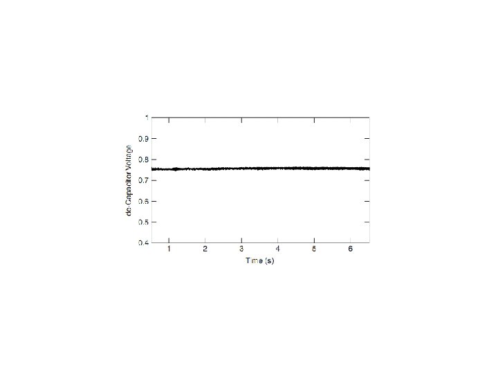
Three cases are considered for line compensation: 1. Total of 50% series compensation by the fixed capacitor. 2. Total of 35% compensation by a fixed capacitor and 15% by an SSSC. 3. Total of 50% compensation by an SSSC. • Eigenvalue analysis is used to show that both cases 1 and 2 of the preceding list reduce the undamping of the concerned torsional mode. • The SSSC of case 2 damps the torsional oscillations effectively with a damping controller. • It may be noted that the SSSC, as a very expensive controller, is not used alone to compensate the line. A practical compensating scheme involves the use of a relatively small rating SSSC in conjunction with a fixed series capacitor. • For the case study system, depicted in Fig. 10. 24 is the response of the SSSC in case 2 to a step increase in the HP turbine’s mechanical torque output. • The generator rotor angle oscillations decay very rapidly, and in the GEN–LP shaft torques, and the subsynchronous oscillations are also stabilized—although slowly. Moreover, the SSSC closely regulates the dc capacitor voltage.

Figure 10. 24 The SSSC response for a step change in the mechanical input of an HP turbine.

APPLICATION OF UPFC

• The two areas exchange power via two transmission lines of unequal power transfer capacity—one operating at 345 k. V, the other at 138 k. V. Although the 345 k. V line is 100 mi long, the 138 k. V system is composed of two parallel 60 mi long lines feeding a load and a single 40 mi long line leading to the other area. • The power transmission capability is determined by the transient stability considerations of the 345 k. V line. The UPFC is installed in the 138 k. V network. • A 3 phase to ground fault is applied on the 345 k. V line for four cycles, and the line is disconnected after the fault. • The maximum stable power flow possible in the 138 k. V line without the UPFC is shown in Fig. 10. 29 to be 176 MW. • However, the power transfer with the UPFC can be increased 181 MW (103%) to 357 MW. Although this power can be raised further by enhancing the UPFC rating, the power increase is correspondingly and significantly lower than the increase in the UPFC rating, thereby indicating that the practical limit on the UPFC size has been attained.

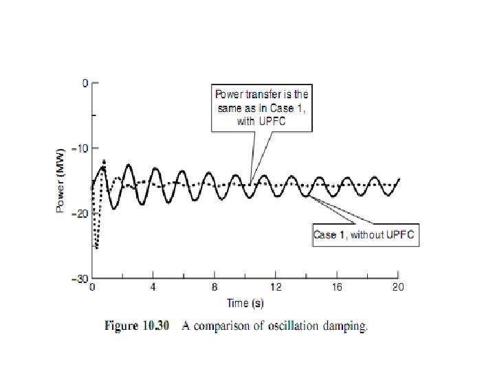
• The UPFC also provides very significant damping to power oscillations when it operates at power flows within the operating limits. • The UPFC response to a 3 phase line to ground fault cleared after four cycles, leaving the 345 k. V line in service, is illustrated in Fig. 10. 30. Because the 345 k. V line remains intact, the oscillation frequency changes from that shown in Fig. 10. 29.
 • The Interline Power Flow Controller (IPFC), proposed")
THE INTERLINE POWER FLOW CONTROLLER (IPFC) • The Interline Power Flow Controller (IPFC), proposed by Gyugyi with Sen and Schauder in 1998, addresses the problem of compensating a number of transmission lines at a given substation. • Conventionally, series capacitive compensation (fixed, thyristor controlled or SSSC based) is employed to increase the transmittable real power over a given line and also to balance the loading of a normally encountered multiline transmission system. • However, independent of their means of implementa tion, series reactive compensators are unable to control the reactive power flow in, and thus the proper load balancing of, the lines.

• This problem becomes particularly evident in those cases where the ratio of reactive to resistive line impedance (X/R) is relatively low. • Series reactive compensation reduces only the effective reactive impedance X and, thus, significantly decreases the effective X/R ratio and thereby increases the reactive power flow and losses in the line. • The IPFC scheme, together with independently controllable reactive series compensation of each individual line, provides a capability to directly transfer real power between the compensated lines. • This capability makes it possible to equalize both real and reactive power flow between the lines; • reduce the burden of overloaded lines by real power transfer; compensate against resistive line voltage drops and the corresponding reactive power demand; • increase the effectiveness of the overall compensating system for dynamic distur bances. • IPFC can potentially provide a highly effective scheme for power transmission management at a multiline substation.

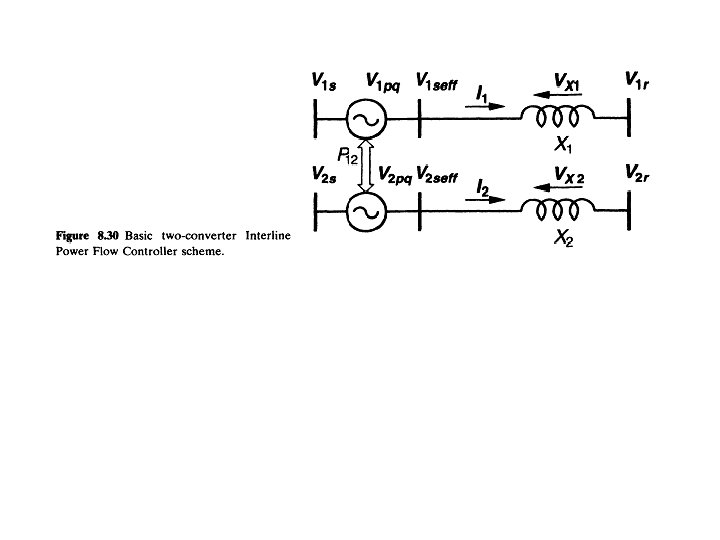
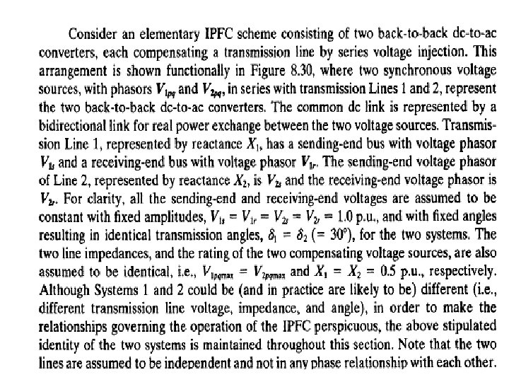
Basic Operating Principles and Characteristics • Interline Power Flow Controller employs a number of dc to ac converters each providing series compensation for a different line. • the IPFC comprises a number of Static Synchronous Series Compensators. • However, within the general concept of the IPFC, the compensating converters are linked together at their dc terminals, as illustrated in Figure 8. 29. • With this scheme, in addition to providing series reactive compensation, any converter can be controlled to supply real power to the common de link from its own transmission line. • Thus, an overall surplus power can be made available from the under utilized lines which then can be used by other lines for real power compensation. • In this way, some of the converters, compensating overloaded lines or lines with a heavy burden of reactive power flow, can be equipped with full two dimensional, reactive and real power control capability, similar to that offered by the UPFC.

• Evidently, this arrangement mandates the rigorous maintenance of the overall power balance at the common dc terminal by appropriate control action, using the general principle that the under loaded lines are to provide help, in the form of appropriate real power transfer, for the overloaded lines.

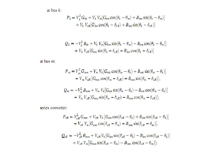
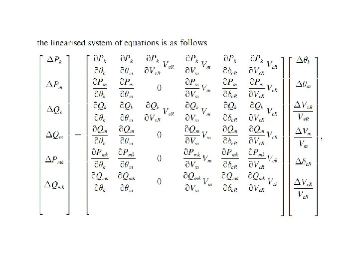
Modeling of SSSC for load flow

• Power flow model The magnitude Vc. R and phase angle δc. R representing the voltage source of series converter. The limits are

Modeling of SSSC for transient stability
- Slides: 65