
Voice Over IP By Jon Peterson Introduction l

Voice Over IP By: Jon Peterson

Introduction l l l Voice Over Internet Protocol (VOIP) communications systems are a rapidly growing technology. Currently VOIP systems make up 1% of telephone communications in the US. VOIP systems allow communications companies to merge their voice and data networks for greater efficiency.
Hardware Design Goals l l Capture and replicate voice signals with quality equivalent or better to that of the Plain Old Telephone System (POTS). Make the VOIP system easy to use – a non-technical user should be able to sit down and use it (Grandma design principle). Must be able to store the user information in nonvolatile memory. Must be able to transfer packets over the internet…
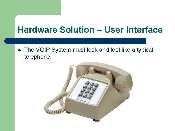
Hardware Solution – User Interface l The VOIP System must look and feel like a typical telephone.
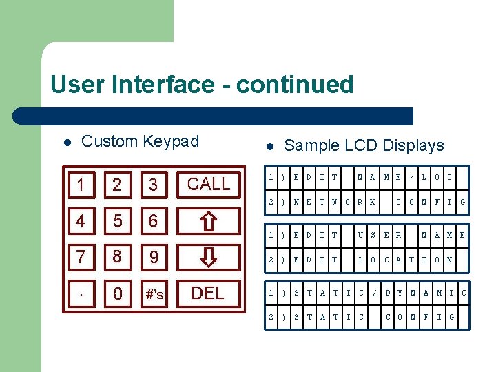
User Interface - continued l Custom Keypad l Sample LCD Displays 1 ) E D I T N A 2 ) N E T W O R K M E / L O C C O N F I G 1 ) E D I T U S E R N A M E 2 ) E D I T L O C A T I O N 1 ) S T A T I C / D Y N A M I C 2 ) S T A T I C C O N F I G
Hardware Solution – µController l l l To accomplish communications over the internet, I needed to pick a suitable network interface chip. The Motorola HC 9 S 12 NE 64 has integrated EMAC and EPHY network layers, so no external chip & bus designs were required. The downside to picking the NE 64 is that it does not include the integrated EEPROM necessary for saving the user’s settings, and it has a very limited amount of RAM.

µController - continued The RJ-45 connector includes integrated transformers to protect the microcontroller from network power surges. The connector also includes integrated LEDs to indicate network status.
Hardware Solution – Audio Quality l l l The audio samples must have a resolution of at least 8 bits. The audio sample rate must be at least 8 k. Hz. The bandwidth of the reproduced audio must be 3 k. Hz or greater (between 300 Hz and 3300 Hz).
Audio Hardware l l For the input circuit, I chose a Motorola MC 33202 P dual, low-voltage op-amp. For the output circuit, I chose two IC’s: – – The Maxim MAX 548 A 8 -bit, low-voltage, SPI Digital to Analog converter. The Motorola MC 34119, low-voltage, audio amplifier.
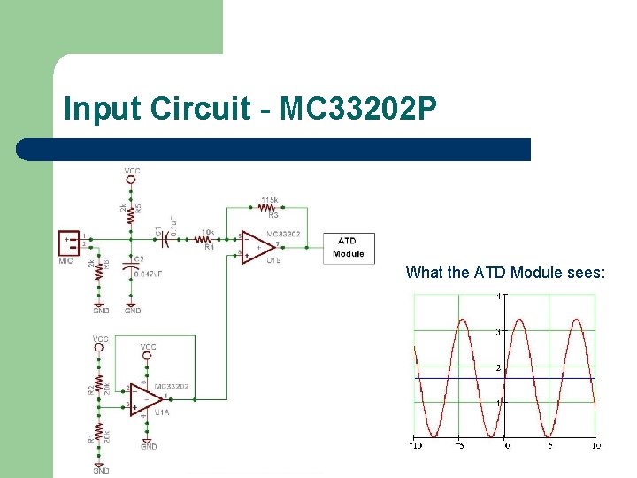
Input Circuit - MC 33202 P What the ATD Module sees:
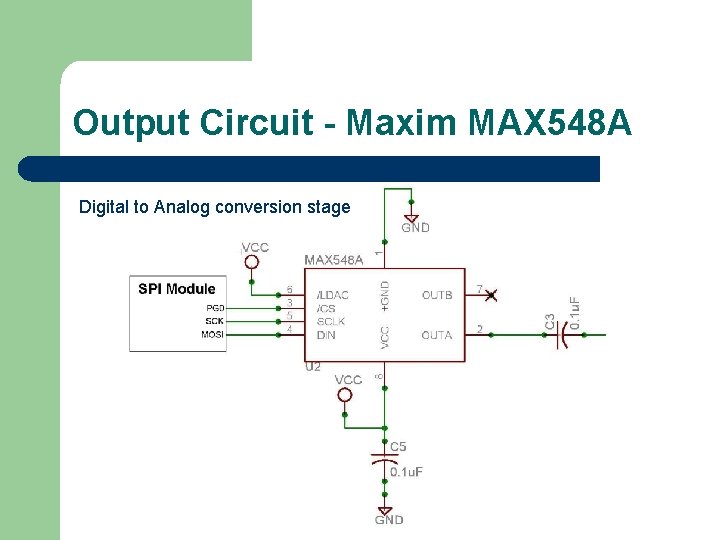
Output Circuit - Maxim MAX 548 A Digital to Analog conversion stage
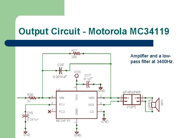
Output Circuit - Motorola MC 34119 Amplifier and a lowpass filter at 3400 Hz.
Hardware Solution – Data Storage l l l Since the Motorola HC 9 S 12 NE 64 does not include the on-chip EEPROM necessary for saving the user’s settings, I had to pick an external device. SPI memory devices are relatively fast (for external memory devices), and easy to implement (Easy = minimal wiring + circuitry) I chose the Atmel AT 25040 A – 512 byte Serial EEPROM
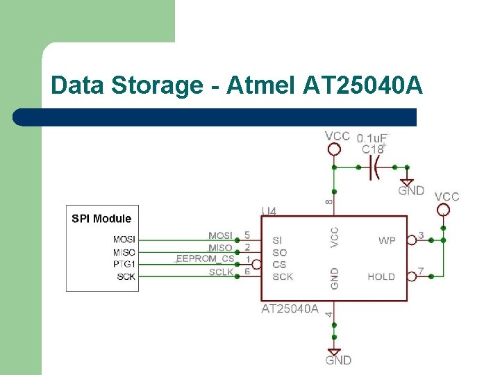
Data Storage - Atmel AT 25040 A
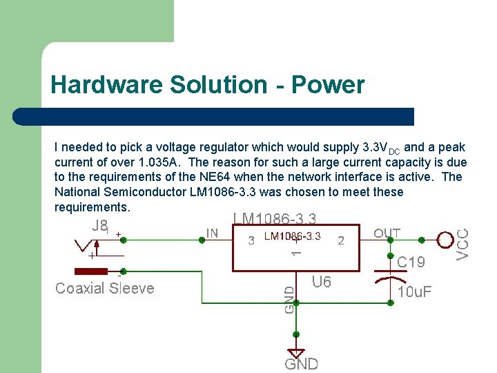
Hardware Solution - Power I needed to pick a voltage regulator which would supply 3. 3 VDC and a peak current of over 1. 035 A. The reason for such a large current capacity is due to the requirements of the NE 64 when the network interface is active. The National Semiconductor LM 1086 -3. 3 was chosen to meet these requirements.

Thank-You! Now I will show you the full schematic, so that you may visualize my design as a whole.
- Slides: 16