VisionBased Detection Tracking and Classification of Vehicles using

Vision-Based Detection, Tracking and Classification of Vehicles using Features and Patterns with Automatic Camera Calibration Neeraj K. Kanhere Committee members Dr. Stanley Birchfield (Advisor) Dr. John Gowdy Dr. Robert Schalkoff Dr. Wayne Sarasua Clemson University July 10 th 2008
 •")
Vehicle tracking Why detect and track vehicles ? • Intelligent Transportation Systems (ITS) • Data collection for transportation engineering applications • Incident detection and emergency response Non-vision sensors • Inductive loop detectors • Piezoelectric and Fiber Optic sensors • The Infra-Red Traffic Logger (TIRTL) • Radar • Laser Vision-based sensors • No traffic disruption for installation and maintenance • Wide area detection with a single sensor • Rich in information for manual inspection
 Vantage (Iteris) Citilog Traficon")
Available video commercial systems Autoscope (Econolite) Vantage (Iteris) Citilog Traficon

Problems with commercial systems Video
 • Computationally efficient • Good")
Related research Region/contour (Magee 04, Gupte et al. 02) • Computationally efficient • Good results when vehicles are well separated 3 D model (Ferryman et al. 98) • Large number of models needed for different vehicle types • Limited experimental results Markov random field (Kamijo et al. 01) • Good results on low angle sequences • Accuracy drops by 50% when sequence is processed in true order Feature tracking (Kim 08, Beymer et al. 97) • Handles partial occlusions • Good accuracy for free flowing as well as congested traffic conditions

Overview of the research Scope of this research includes three problems Vehicle detection and tracking Features Camera calibration Patterns Vehicle classification and traffic parameter extraction

Overview of the research Scope of this research includes three problems Vehicle detection and tracking Features Camera calibration Patterns Vehicle classification and traffic parameter extraction

Problem of depth ambiguity Image plane Focal point Road • Pinhole camera model • All points along the ray map to the same image location

Problem of depth ambiguity 1 Perspective view 2 3 Top view An image point on the roof of the trailer is in the second lane 4

Problem of depth ambiguity 1 Perspective view 2 3 Top view The same image point is now in the last lane 4

Problem of depth ambiguity 1 2 3 4

Problem of scale change Grouping based on pixel distances fails when there is a large scale change in the scene.

Feature segmentation using 3 D coordinates Background model Background subtraction Calibration 1 Correspondence 4 Single frame estimation 2 3 Rigid motion constraint Neeraj Kanhere, Stanley Birchfield and Shrinivas Pundlik (CVPR 2005) Neeraj Kanhere, Stanley Birchfield and Wayne Sarasua (TRR 2006) Normalized cuts on affinity matrix 5

Improved real-time implementation Image frame Feature tracking Background subtraction Filtering Group stable features PLP estimation Group unstable features Correspondence, Validation and Classification Calibration Vehicle trajectories and data Neeraj Kanhere and Stanley Birchfield (IEEE Transactions on Intelligent Transportation Systems, 2008)
 User draws two lines (red) corresponding to the edges of")
Offline camera calibration 1) User draws two lines (red) corresponding to the edges of the road 2) User draws a line (green) corresponding to a known length along the road 3) Using either road width or camera height, a calibrated detection zone is computed

Background subtraction and filtering Background features Vehicle features Shadow features Only vehicles features are considered in further processing, reducing distraction from shadows
 • PLP is the projection of a feature on the")
Plumb line projection (PLP) • PLP is the projection of a feature on the road in the foreground image. • With this projection, an estimate of 3 D location of the feature is obtained.

Error in 3 D estimation with PLP

Selecting stable features Feature is stable if & Features are stable if • close to the ground, and • slope is small at plumb line projection

Grouping of stable features Within each lane: Seed growing is used to group features with similar Y coordinate Across lanes: Groups with similar Y coordinate are merged if their combined width is acceptable

Grouping unstable features Location of an unstable feature is estimated with respect to each stable group using rigid motion constraint. Centroid of a stable feature group Unstable feature

Grouping unstable features Likelihood of the unstable feature is computed based on the estimated 3 D location. score for group i validity of location Unstable feature is assigned to the group if it is likely to belong to that group & bias terms for large vehicles Unlikely to belong to any other group a is best matching stable group. b is second best matching stable group.

Overview of the research Scope of this research includes three problems Vehicle detection and tracking Features Camera calibration Patterns Vehicle classification and traffic parameter extraction

Combining pattern recognition Feature grouping Pattern recognition • Works under varying camera placement • Needs a trained detector for significantly different viewpoints • Eliminates false counts due to shadows but headlight reflections are still a problem • Does not get distracted by headlight reflections • Needs calibration • Does not need calibration • Handles lateral occlusions but fails in case of back-to-back occlusions • Handles back-to-back occlusions but difficult to handle lateral occlusions

Combining pattern recognition Lateral occlusion Back-to-back occlusion • Handles lateral occlusions but fails in case of back-to-back occlusions • Handles back-to-back occlusions but difficult to handle lateral occlusions B B A A
 Offline supervised training of the detector using training images")
Boosted Cascade Vehicle Detector (BCVD) Offline supervised training of the detector using training images Positive training samples Vehicles detected in new images Run-time Training BCVD Negative training samples Cascade architecture Stage 1 Stage 2 Stage n Detection …. Rejected sub-windows

Rectangular features with Integral images 1. A 1 C B 2 D 3 Haar-like rectangular features Fast computation and fast scaling sum(A) sum(A+B) sum(A+C) sum(A+B+C+D) = = val(1) val(2) val(3) val(4) 4 sum(D) = val(4) – val(3) – val(2) + val(1) Viola and Jones, CVPR 2001

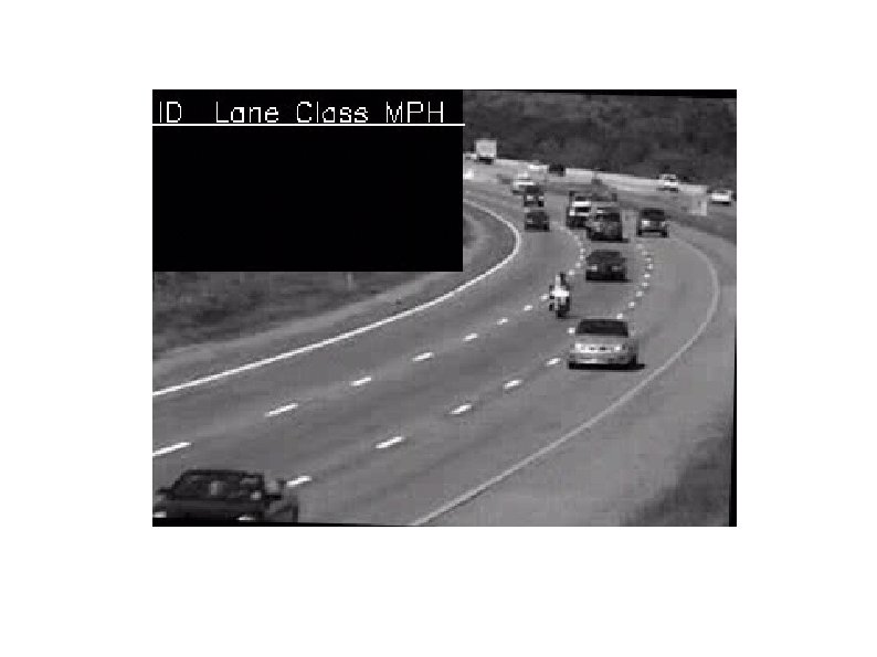
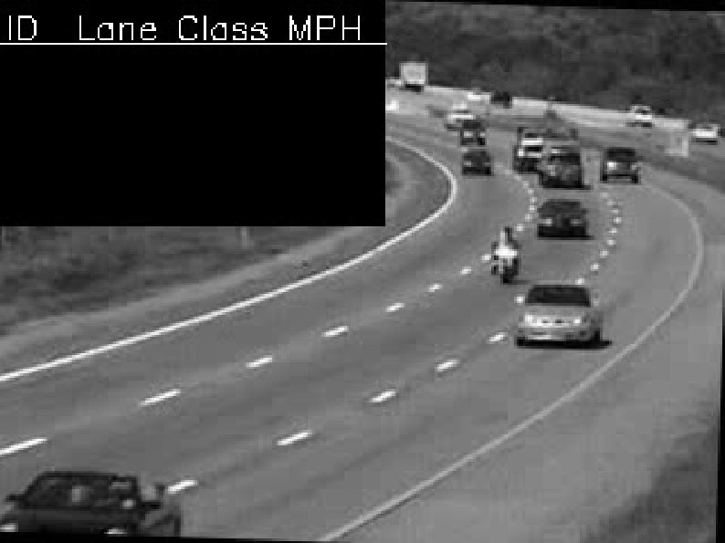
Sample results for static vehicle detection

Overview of the research Scope of this research includes three problems Vehicle detection and tracking Camera calibration Vehicle classification and traffic parameter extraction
![Two calibration approaches Image-world correspondences f, h, Φ, θ … M[3 x 4] Direct](http://slidetodoc.com/presentation_image_h2/4ef05a0c851ff1fe8608718f3d09fa45/image-31.jpg "Two calibration approaches Image-world correspondences f, h, Φ, θ … M[3 x 4] Direct")
Two calibration approaches Image-world correspondences f, h, Φ, θ … M[3 x 4] Direct estimation of projective transform M[3 x 4] Estimation of parameters for the assumed camera model • Goal is to estimate 11 elements of a matrix which transforms points in 3 D to a 2 D plane • Goal is to estimate camera parameters such as focal length and pose • Harder to incorporate scenespecific knowledge • Easier to incorporate known quantities and constraints

Direct estimation of projective matrix Atleast six points are required to estimate the 11 unknown parametes of the projective matrix

Camera calibration modes Assumptions: Flat road surface, zero skew, square pixels, and principal point at image center Known quantities: Width (W) or, Length (L), or Camera height (H)

Camera calibration modes Assumptions: Flat road surface, zero skew, square pixels, principal point at image center, and zero roll angle Known quantities: W or L or H

Camera calibration modes Assumptions: Flat road surface, zero skew, square pixels, principal point at image center, and zero roll angle Known quantities: {W, L} or {W, H} or {L, H}
 Song et al. (2006) Schoepflin")
Previous approaches to automatic calibration Dailey et al. (2000) Song et al. (2006) Schoepflin and Dailey (2003) Zhang et al. (2008) Previous approaches: • Need background image • Sensitive to image processing parameters • Affected by spillover • Do not work at night

Our approach to automatic calibration • Does not depend on road markings • Does not require scene specific parameters such as lane dimensions • Works in presence of significant spill-over (low height) • Works under night-time condition (no ambient light) Neeraj Kanhere, Stanley Birchfield and Wayne Sarasua (TRR 2008)

Estimating vanishing points Vanishing point in the direction of travel is estimated using vehicle tracks Orthogonal vanishing point is estimated using strong gradients or headlights
 Pan angle Tilt angle Camera height")
Automatic calibration algorithm Focal length (pixels) Pan angle Tilt angle Camera height

Overview of the research Vehicle detection and tracking Camera calibration Vehicle classification and traffic parameter extraction

Vehicle classification based on axle counts FHWA highway manual lists 13 vehicle classes based on axle counts: 1. Motorcycles 2. Passenger cars 3. Other two-axle, four-tire single unit vehicles 4. Buses 5. Two-axle, six-tire, single-unit trucks 6. Three-axle single-unit trucks 7. Four or more axle single-unit trucks 8. Four or fewer axle single-trailer trucks 9. Five-axle single-trailer trucks 10. Six or more axle single-trailer trucks 11. Five or fewer axle multi-trailer trucks 12. Six axle multi-trailer trucks 13. Seven or more axle multi-trailer trucks
")
Vehicle classification based on length Thanks to Steven Jessberger (FHWA)

Vehicle classification based on length Four classes for length-based classification 1. Motorcycles 2. Passenger cars 3. Other two-axle, four-tire single unit vehicles 4. 5. 6. 7. 8. Buses Two-axle, six-tire, single-unit trucks Three-axle single-unit trucks Four or more axle single-unit trucks Four or fewer axle single-trailer trucks 9. Five-axle single-trailer trucks 10. Six or more axle single-trailer trucks 11. Five or fewer axle multi-trailer trucks 12. Six axle multi-trailer trucks 13. Seven or more axle multi-trailer trucks
")
Traffic parameters ü ü Volumes Lane counts Speeds Classification (three classes)

Results

Quantitative results

Results for automatic camera calibration

Demo

Conclusion Research contributions: • A system for detection, tracking and classification of vehicles • Combination of feature tracking and background subtraction to group features in 3 D • Pattern recognition-based approach to detection and tracking of vehicles • Automatic camera calibration technique which doesn’t need pavement markings and works even in absence of ambient light Future work should be aimed at: • Extending automatic calibration to handle non-zero roll • Improving and extending vehicle classification • Long term testing of the system in day and night conditions • A framework for combining pattern recognition with features

Questions and Discussion

Thank You

 Schoepflin and Dailey (2003) •")
Previous approaches to automatic calibration Dailey et al. (2000) Schoepflin and Dailey (2003) • Avoids calculating camera parameters • Based on assumptions that reduce the problem to 1 -D geometry Lane activity map Peaks at lane centers • Uses parameters from the distribution of vehicle lengths. • Uses two vanishing points • Lane activity map sensitive of spill-over • Correction of lane activity map needs Song et al. (2006) background image • Known camera height • Needs background image • Depends on detecting road markings
 • PLP is the projection of a feature on the")
Plumb line projection (PLP) • PLP is the projection of a feature on the road in the foreground image. • With this projection, an estimate of 3 D location of the feature is obtained.
- Slides: 55