
VIRTUAL ROUTER Kien A Hua Data Systems Lab

VIRTUAL ROUTER Kien A. Hua Data Systems Lab School of EECS University of Central Florida
Outline • Mobile Ad Hoc Networks • Virtual Router Approach – Routing – Data Forwarding • Cooperation Enforcement in Virtual Router Approach • Simulation Results • Conclusions 2

Wireline Communications Infrastructure Router Router S Routers help forward data packets D
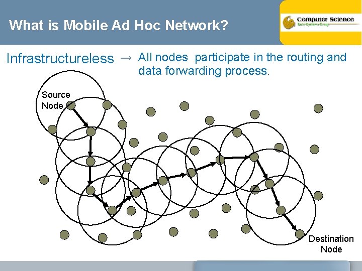
What is Mobile Ad Hoc Network? Infrastructureless → All nodes participate in the routing and data forwarding process. Source Node Destination Node
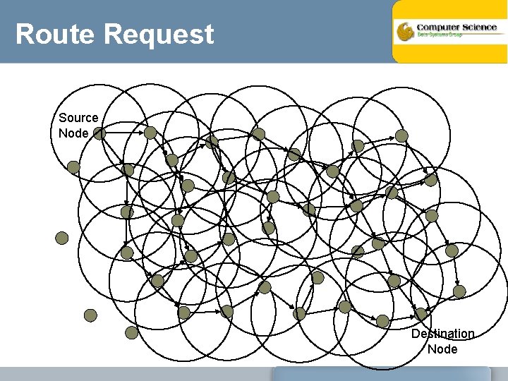
Route Request Source Node Destination Node
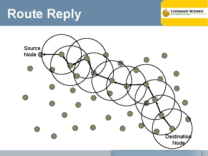
Route Reply Source Node Destination Node
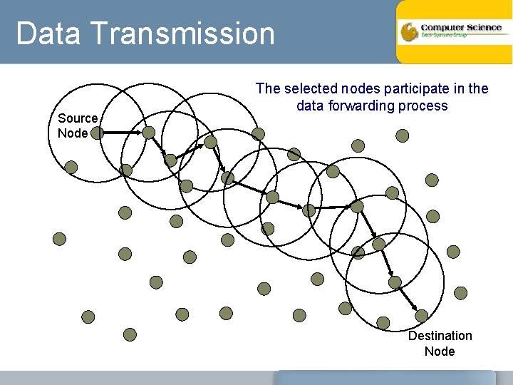
Data Transmission Source Node The selected nodes participate in the data forwarding process Destination Node
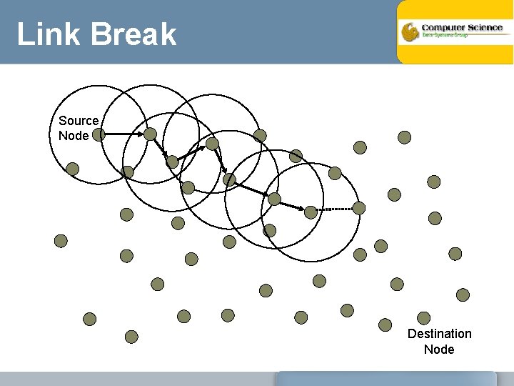
Link Break Source Node Destination Node
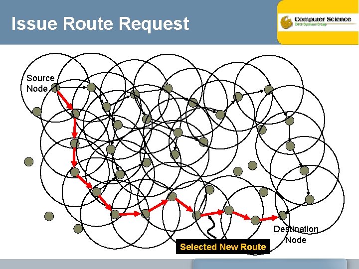
Issue Route Request Source Node Selected New Route Destination Node
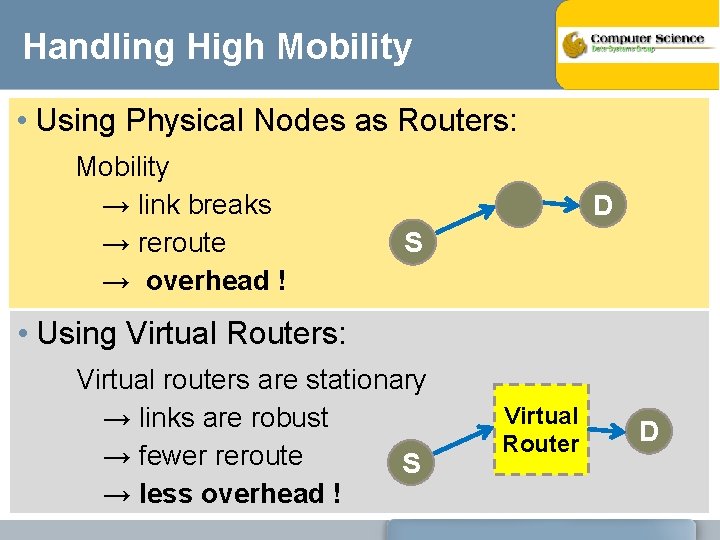
Handling High Mobility • Using Physical Nodes as Routers: Mobility → link breaks → reroute → overhead ! D S • Using Virtual Routers: Virtual routers are stationary → links are robust → fewer reroute S → less overhead ! Virtual Router D
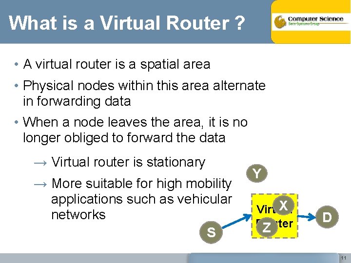
What is a Virtual Router ? • A virtual router is a spatial area • Physical nodes within this area alternate in forwarding data • When a node leaves the area, it is no longer obliged to forward the data → Virtual router is stationary → More suitable for high mobility applications such as vehicular networks S Y X Virtual Router Z D 11
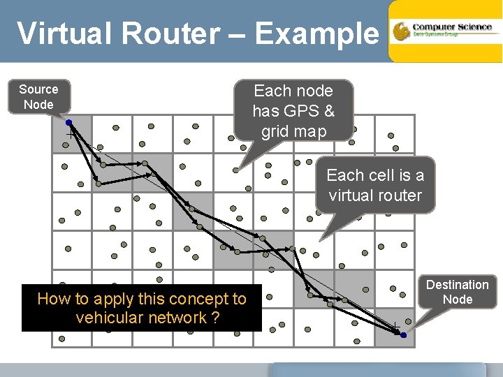
Virtual Router – Example Source Node Each node has GPS & grid map Each cell is a virtual router How to apply this concept to vehicular network ? Destination Node
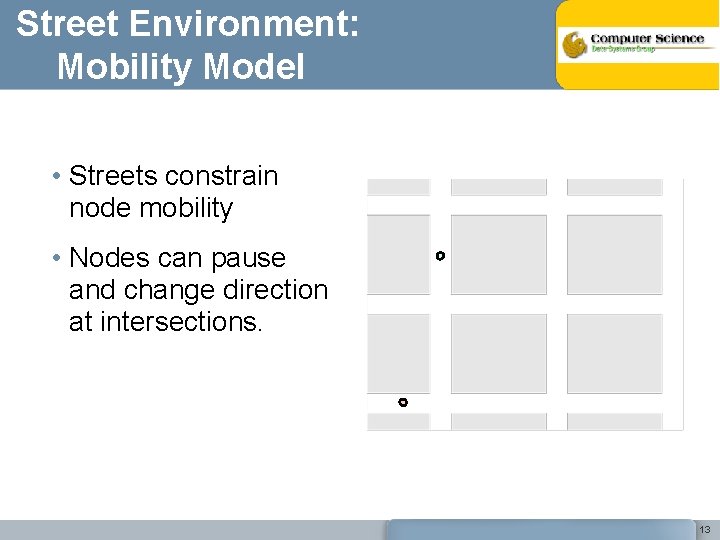
Street Environment: Mobility Model • Streets constrain node mobility • Nodes can pause and change direction at intersections. 13
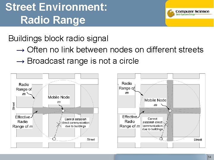
Street Environment: Radio Range Buildings block radio signal → Often no link between nodes on different streets → Broadcast range is not a circle 14
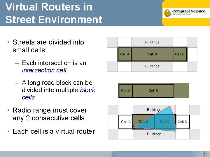
Virtual Routers in Street Environment • Streets are divided into small cells: – Each intersection is an intersection cell – A long road block can be divided into multiple block cells • Radio range must cover any 2 consecutive cells • Each cell is a virtual router 15
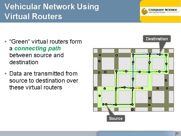
Vehicular Network Using Virtual Routers Destination • “Green” virtual routers form a connecting path between source and destination • Data are transmitted from source to destination over these virtual routers Source 16
Location Discovery Similar to standard route request • A source node broadcasts a Location Discovery (LD) packet • This LD packet propagates until it reaches the destination node • When the LD packet arrives at the destination, it replies with a Location Reply (LR) packet that includes the location of the destination router (i. e. , destination cell). Subsequently, every data packet carries the ID’s of the source and destination routers 17
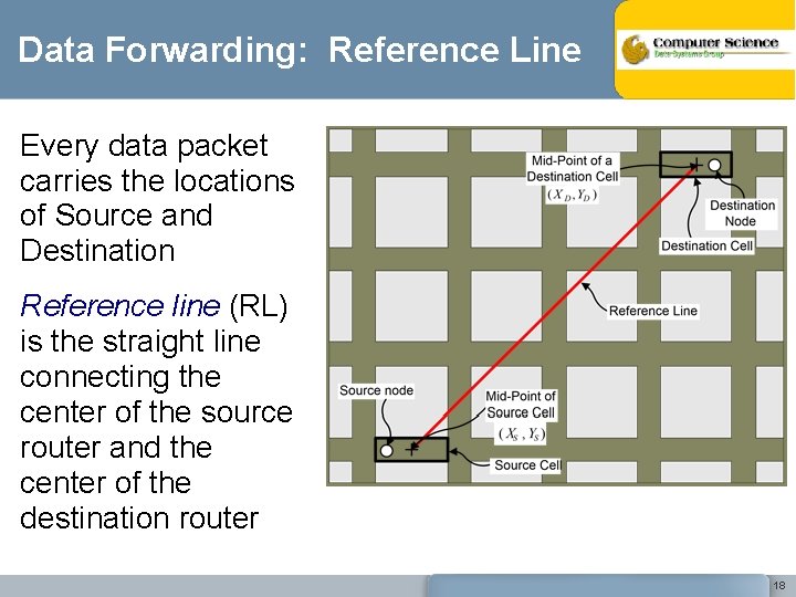
Data Forwarding: Reference Line Every data packet carries the locations of Source and Destination Reference line (RL) is the straight line connecting the center of the source router and the center of the destination router 18
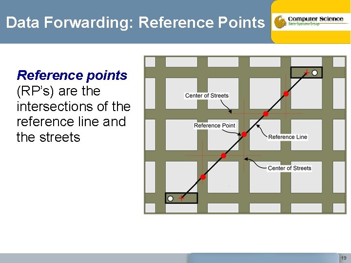
Data Forwarding: Reference Points Reference points (RP’s) are the intersections of the reference line and the streets 19
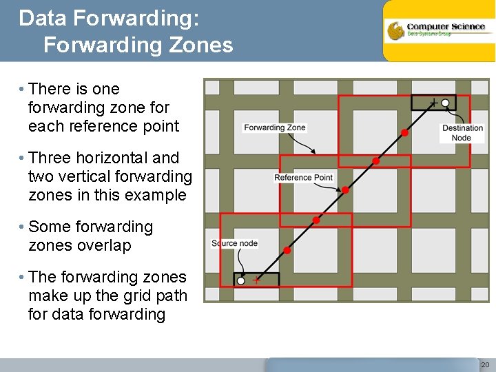
Data Forwarding: Forwarding Zones • There is one forwarding zone for each reference point • Three horizontal and two vertical forwarding zones in this example • Some forwarding zones overlap • The forwarding zones make up the grid path for data forwarding 20
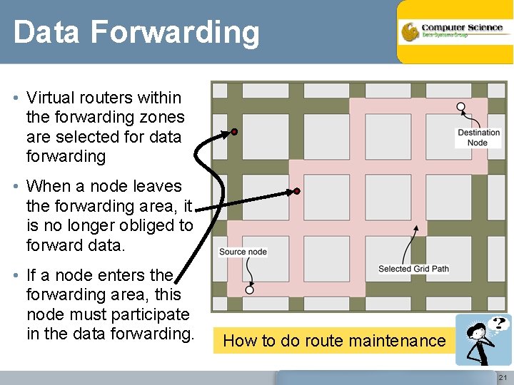
Data Forwarding • Virtual routers within the forwarding zones are selected for data forwarding • When a node leaves the forwarding area, it is no longer obliged to forward data. • If a node enters the forwarding area, this node must participate in the data forwarding. How to do route maintenance 21
Connection Maintenance Destination node moves away from current router → Reference line changes → → → Reference points changes Forwarding zones changes Need a new connection path Essentially no overhead Route Maintenance: – – The destination node periodically updates its location with the source node. If this fails, source issues a location discovery packet 22
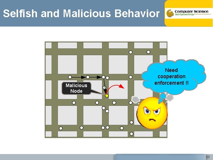
Selfish and Malicious Behavior Malicious Node It works as long Need as nodes cooperation cooperate !! enforcement 23
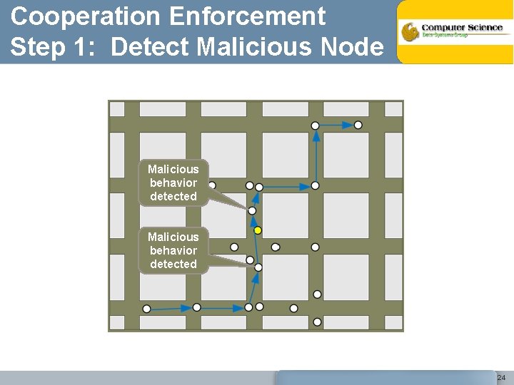
Cooperation Enforcement Step 1: Detect Malicious Node Malicious behavior detected Malicious node Malicious behavior detected 24
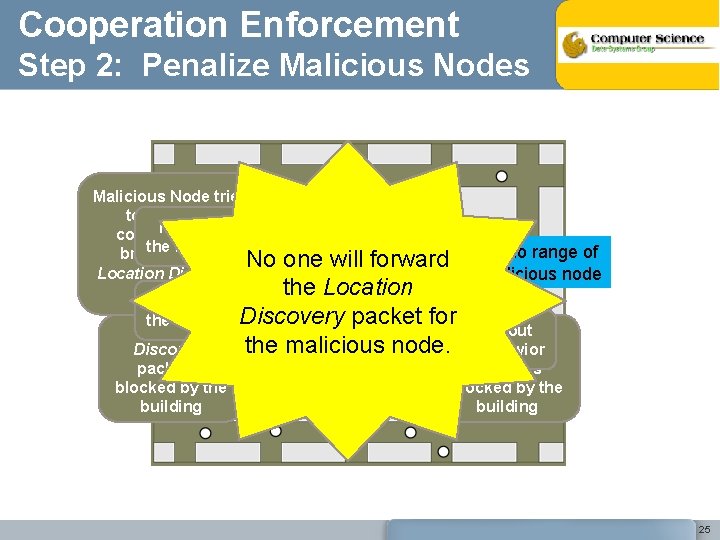
Cooperation Enforcement Step 2: Penalize Malicious Nodes Malicious Node tries to establish I knowby about connection the misbehavior radio range of broadcasting No one will forward Location Discovery malicious node the Location packet I know about Discovery packet for the misbehavior Location I know about the malicious node. Discovery the misbehavior packet is blocked by the building 25
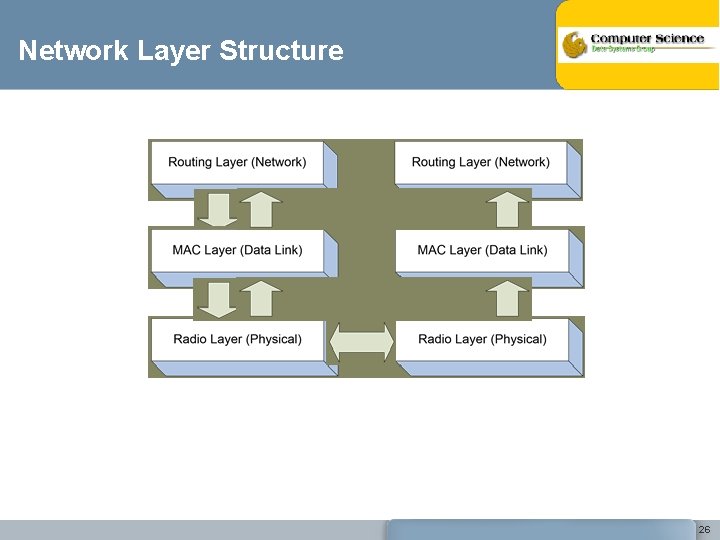
Network Layer Structure 26
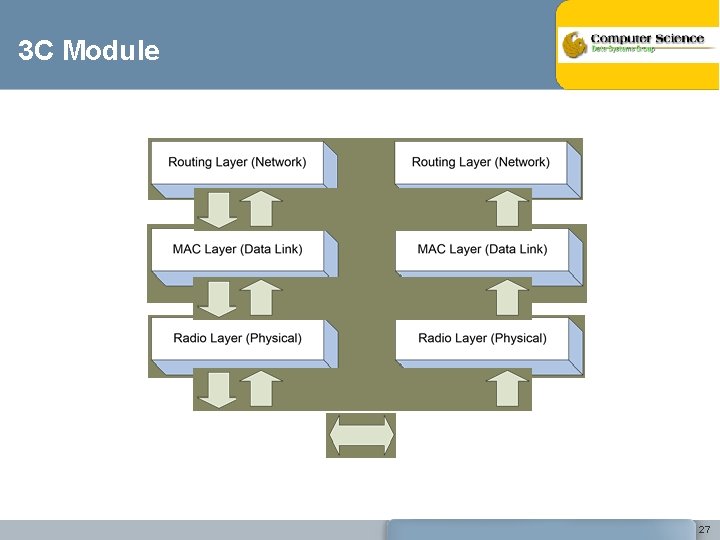
3 C Module 27
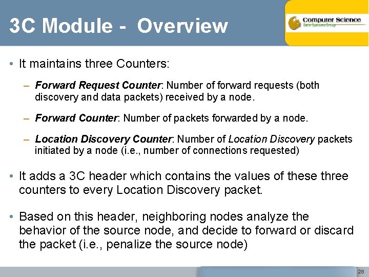
3 C Module - Overview • It maintains three Counters: – Forward Request Counter: Number of forward requests (both discovery and data packets) received by a node. – Forward Counter: Number of packets forwarded by a node. – Location Discovery Counter: Number of Location Discovery packets initiated by a node (i. e. , number of connections requested) • It adds a 3 C header which contains the values of these three counters to every Location Discovery packet. • Based on this header, neighboring nodes analyze the behavior of the source node, and decide to forward or discard the packet (i. e. , penalize the source node) 28
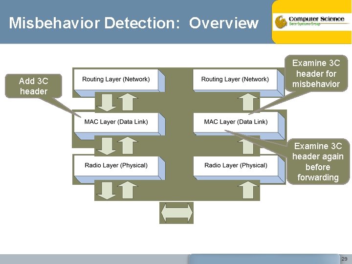
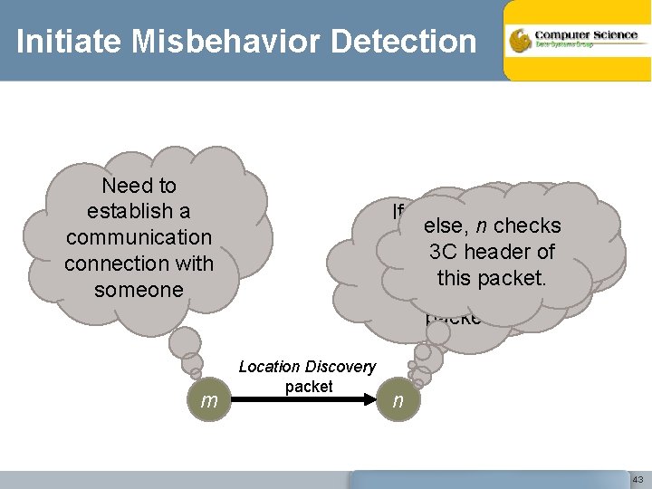
Misbehavior Detection: Overview Add 3 C header Examine 3 C header for misbehavior Examine 3 C header again before forwarding 29
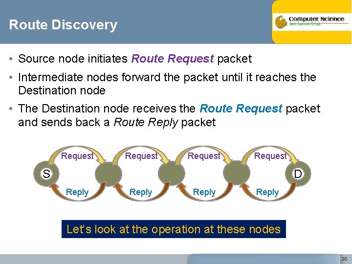
Route Discovery • Source node initiates Route Request packet • Intermediate nodes forward the packet until it reaches the Destination node • The Destination node receives the Route Request packet and sends back a Route Reply packet Request S D Reply Let’s look at the operation at these nodes 30
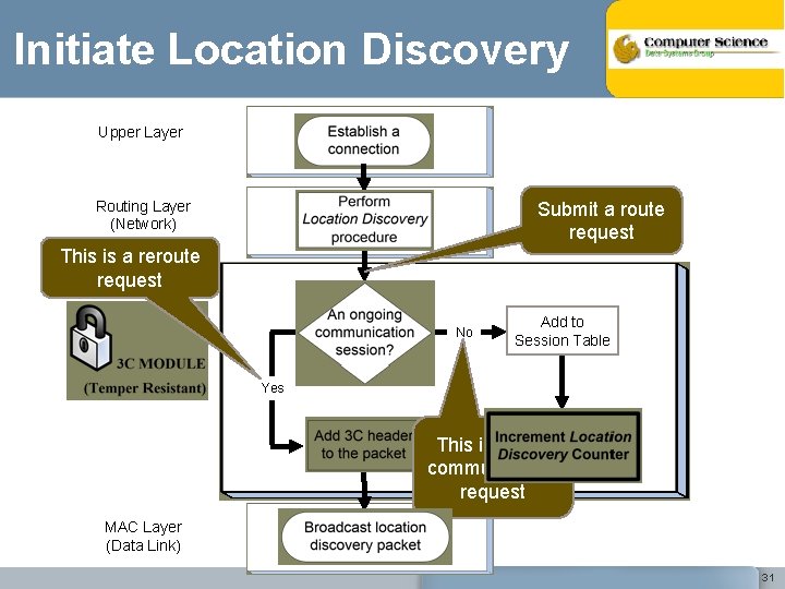
Initiate Location Discovery Upper Layer Routing Layer (Network) Submit a route request This is a reroute request No Add to Session Table Yes This is a new communication request MAC Layer (Data Link) 31
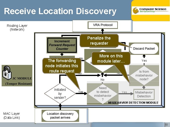
Receive Location Discovery Routing Layer (Network) Penalize the requester Yes No The forwarding node initiates this route request No More on this module later… Yes No No Initiated by sender? Yes MISBEHAVIOR DETECTION MODULE MAC Layer (Data Link) 32
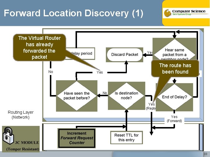
Forward Location Discovery (1) The Virtual Router has already forwarded the packet No Yes The route has been found Yes No No No Routing Layer (Network) Yes (Reply) Yes (Forward) 33
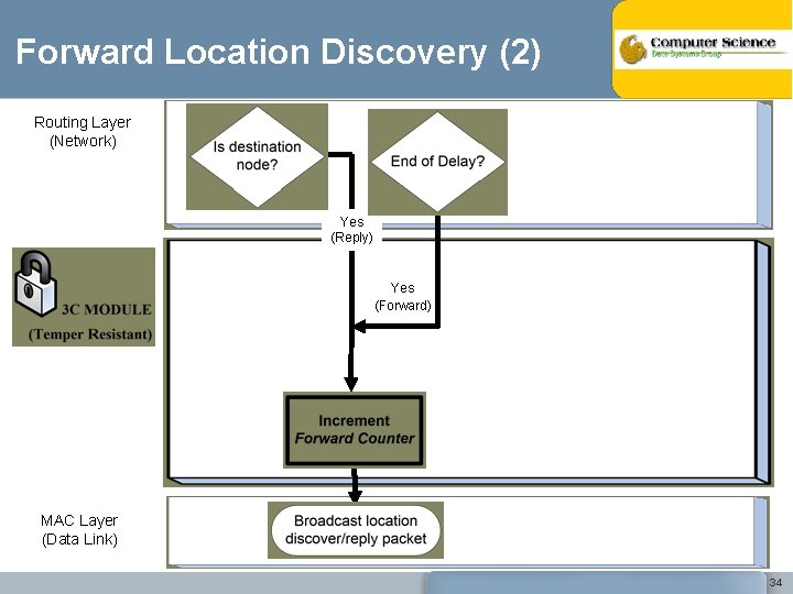
Forward Location Discovery (2) Routing Layer (Network) Yes (Reply) Yes (Forward) MAC Layer (Data Link) 34
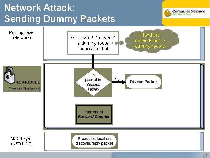
Network Attack: Sending Dummy Packets Routing Layer (Network) Flood the network with a dummy record Generate & “forward” a dummy route request packet No MAC Layer (Data Link) 35
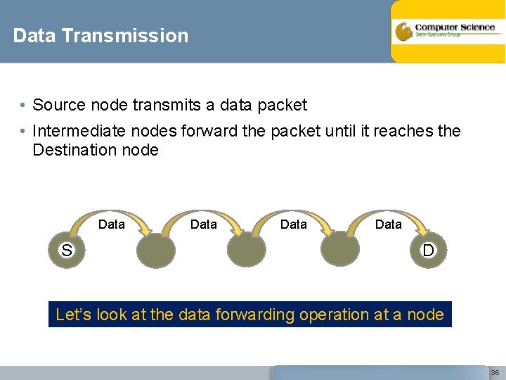
Data Transmission • Source node transmits a data packet • Intermediate nodes forward the packet until it reaches the Destination node Data S Data D Let’s look at the data forwarding operation at a node 36
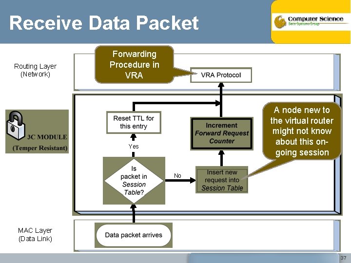
Receive Data Packet Routing Layer (Network) Forwarding Procedure in VRA A node new to the virtual router might not know about this ongoing session Yes No MAC Layer (Data Link) 37
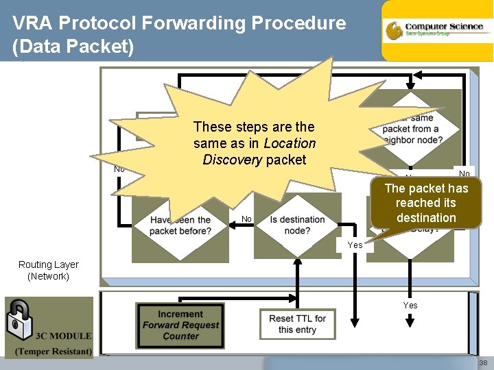
VRA Protocol Forwarding Procedure (Data Packet) No These steps are the same as in Location Discovery packet Yes No No The packet has reached its destination No Yes Routing Layer (Network) Yes 38
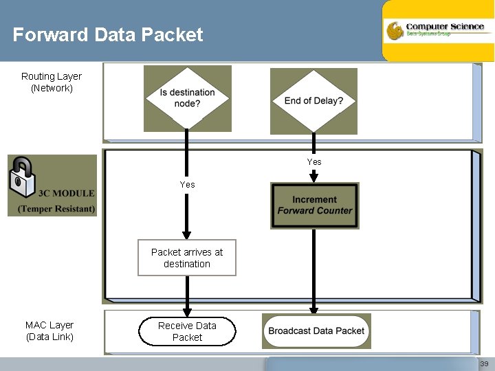
Forward Data Packet Routing Layer (Network) Yes Packet arrives at destination MAC Layer (Data Link) Receive Data Packet 39
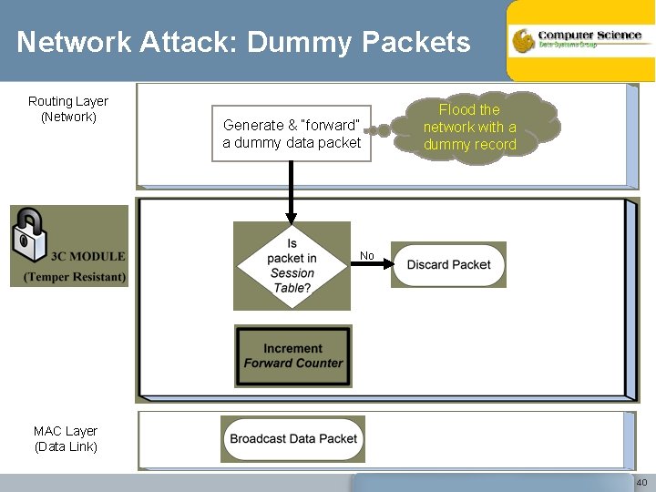
Network Attack: Dummy Packets Routing Layer (Network) Generate & “forward” a dummy data packet Flood the network with a dummy record No MAC Layer (Data Link) 40
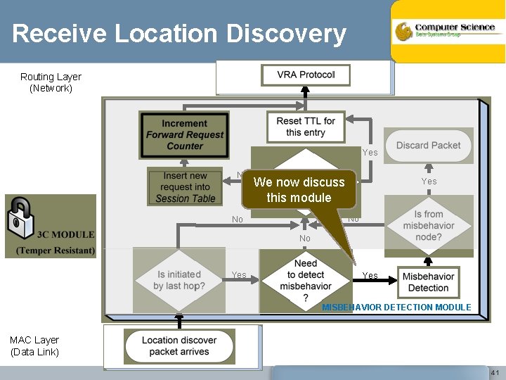
Receive Location Discovery Routing Layer (Network) Yes No We now discuss this module Yes No No No Yes MISBEHAVIOR DETECTION MODULE MAC Layer (Data Link) 41
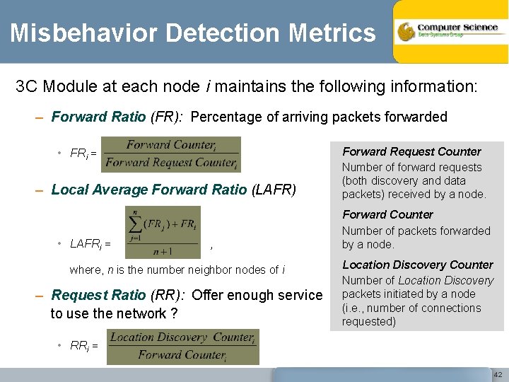
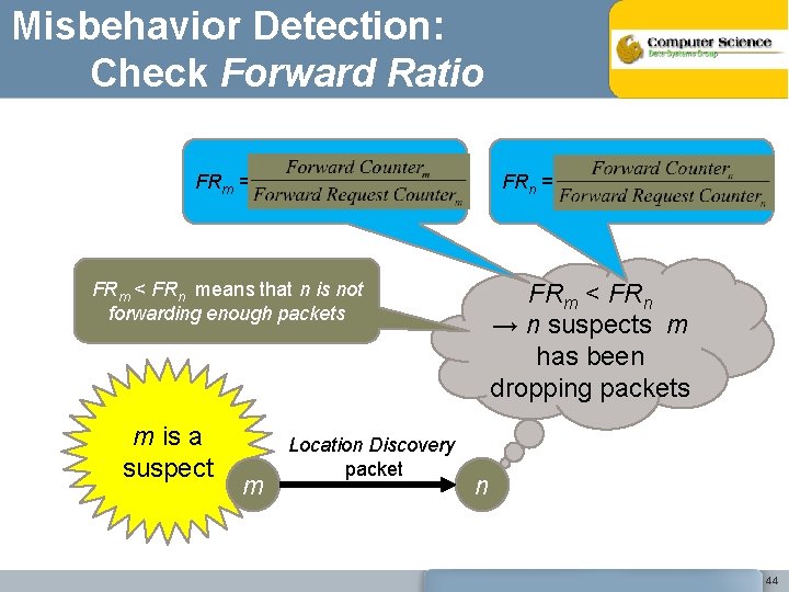
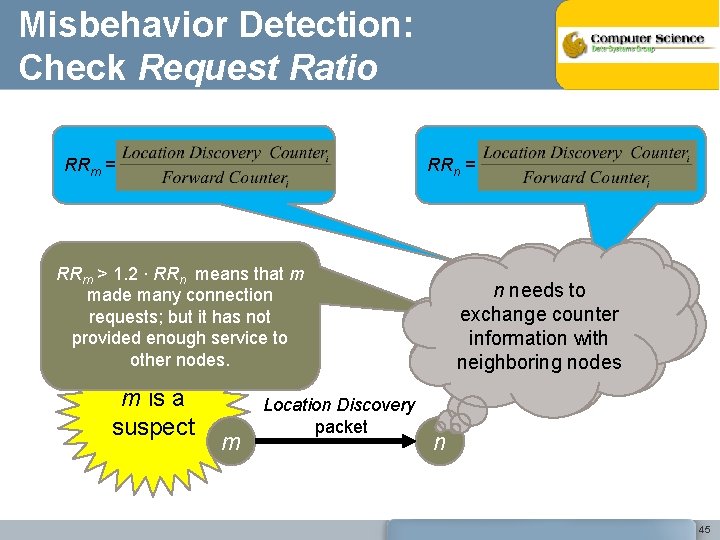
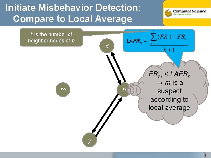
Misbehavior Detection Metrics 3 C Module at each node i maintains the following information: – Forward Ratio (FR): Percentage of arriving packets forwarded • FRi = – Local Average Forward Ratio (LAFR) • LAFRi = , where, n is the number neighbor nodes of i – Request Ratio (RR): Offer enough service to use the network ? Forward Request Counter Number of forward requests (both discovery and data packets) received by a node. Forward Counter Number of packets forwarded by a node. Location Discovery Counter Number of Location Discovery packets initiated by a node (i. e. , number of connections requested) • RRi = 42
Initiate Misbehavior Detection Need to establish a communication connection with someone m If m is not the n checks Iselse, the forwarder source node, n 3 C header of the initiator proceeds to of thispacket. ? this forward the packet Location Discovery packet n 43
Misbehavior Detection: Check Forward Ratio FRm = FRn = FRm < FRn means that n is not forwarding enough packets m is a suspect m Location Discovery packet FRm < FRn → n suspects m has been dropping packets n 44
Misbehavior Detection: Check Request Ratio RRm = RRn = RRm > 1. 2 ∙ RRn means that m made many connection requests; but it has not provided enough service to other nodes. m is a suspect m Location Discovery packet RRnmneeds > 1. 2*RR to n → n suspects exchange counterm information with has been neighboringpackets nodes dropping n 45
Initiate Misbehavior Detection: Compare to Local Average k is the number of neighbor nodes of n LAFRn = x m n n exchanges FRmcounters < LAFRn → m is awith information neighboring suspect nodes to according local average y 46
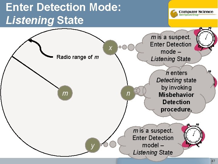
Enter Detection Mode: Listening State m is a suspect. Enter Detection mode – Listening State x Radio range of m m n y n enters m is a suspect. Detecting state by. Enter invoking Detection Misbehavior mode – Detection Listening State procedure. m is a suspect. Enter Detection model – Listening State 47
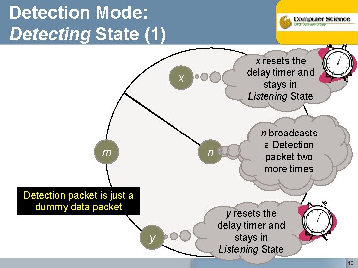
Detection Mode: Detecting State (1) x resets the delay timer and stays in Listening State x m n Detection packet is just a dummy data packet y nnbroadcasts generates a Detection and broadcasts packet two a Detection more times packet y resets the delay timer and stays in Listening State 48
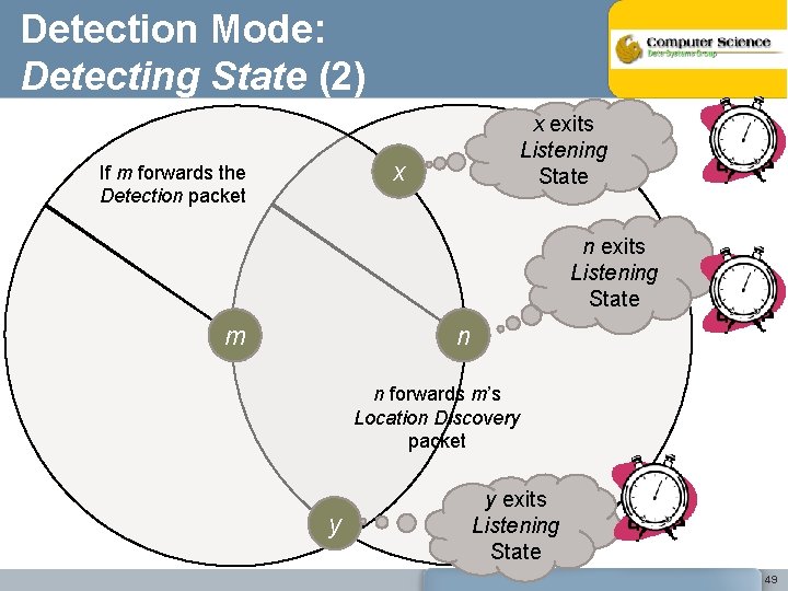
Detection Mode: Detecting State (2) x exits Listening State x If m forwards the Detection packet n exits Listening State m n n forwards m’s Location Discovery packet y y exits Listening State 49
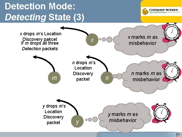
Detection Mode: Detecting State (3) x drops m’s Location Discovery pakcet If m drops all three Detection packets m y drops m’s Location Discovery packet x marks m as misbehavior x n drops m’s Location Discovery packet y n n marks m as misbehavior y marks m as misbehavior 50
Simulation Setting • Simulator: Glo. Mo. Sim. • Constant-bit-rate sessions of 512 -byte packets. • Radio propagation range is 375 meters, and channel capacity is 2 Mbits/sec. • Street width is 10 meters, and building block size is 100 m by 100 m. • Initial nodes placement: 2 nodes per intersection, and 8 nodes per block. • Mobility model: At intersections, a node pauses for a period of time, and then probabilistically changes its direction of movement. • Speed: random between 0 m/s and 25 m/s (or 56 miles/hr). • Pause time: random between 0 and 20 seconds. • 100 simulation runs with different seed numbers for each scenario. • Number of misbehaving nodes: 5%, 10%, 20%, and 30% of total number of nodes. 51
Schemes and Malicious Behavior • Schemes compared: Ø Reference scheme: All nodes act collaboratively and relay data for each other. Ø Defenseless scheme: No detection mechanism is implemented. The network is totally “defenseless”. Ø 3 CE (3 -Counter Enforcement) scheme: misbehaving nodes are detected and punished. • Malicious Behavior: Ø A malicious node recognizes that it is being punished when its Location Discovery packet has been dropped four consecutively times. Ø Once malicious nodes recognize the punishment, they participate in data forwarding to rejoin the network. 52
Performance Metrics • Packet Delivered Ratio (P) – Percentage of data packets successfully delivered to their destination. • Misbehaving Node Detection Ratio (D) – Percentage of misbehaving nodes detected • False Accusation Rate (F) – Percentage of detected nodes incorrectly accused 53
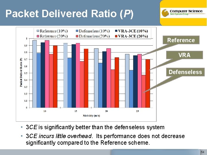
Packet Delivered Ratio (P) Reference VRA Defenseless • 3 CE is significantly better than the defenseless system • 3 CE incurs little overhead. Its performance does not decrease significantly compared to the Reference scheme. 54
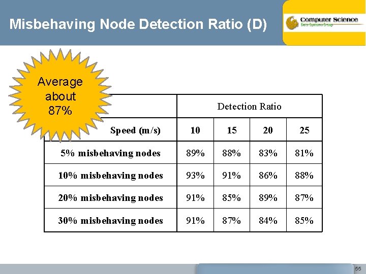
Misbehaving Node Detection Ratio (D) Average about 87% Detection Ratio Speed (m/s) 10 15 20 25 5% misbehaving nodes 89% 88% 83% 81% 10% misbehaving nodes 93% 91% 86% 88% 20% misbehaving nodes 91% 85% 89% 87% 30% misbehaving nodes 91% 87% 84% 85% 55
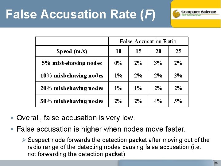
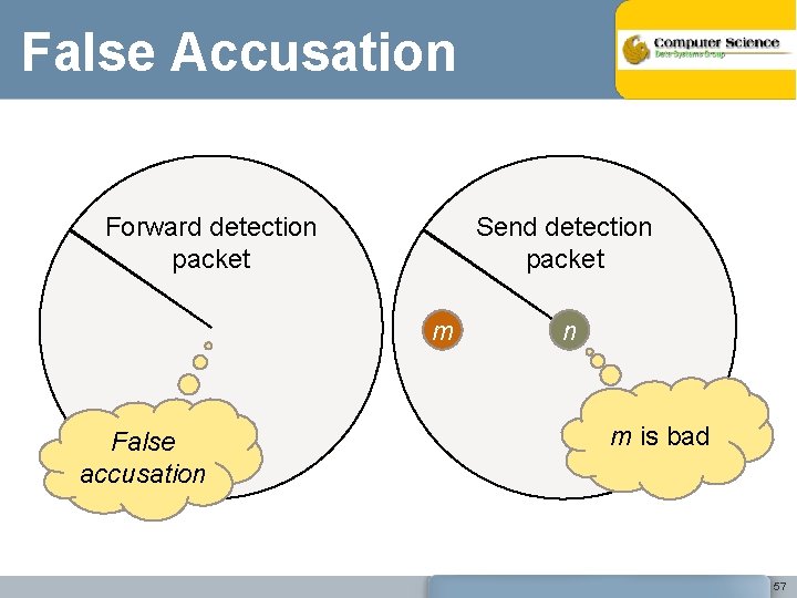
False Accusation Rate (F) False Accusation Ratio Speed (m/s) 10 15 20 25 5% misbehaving nodes 0% 2% 3% 2% 10% misbehaving nodes 1% 2% 2% 3% 20% misbehaving nodes 1% 1% 2% 2% 30% misbehaving nodes 2% 2% 4% 5% • Overall, false accusation is very low. • False accusation is higher when nodes move faster. Ø Suspect node forwards the detection packet after moving out of the radio range of the detecting nodes causing false accusation (i. e. , not forwarding the detection packet) 56
False Accusation Forward detection packet Send detection packet m False accusation n m is bad 57
Conclusions • The Virtual Router approach has been shown to provide better performance than standard routing based on physical nodes • 3 CE (3 Counters Enforcement) cooperation enforcement technique further improves the Virtual Router approach • Our simulation results indicate: – improved network throughput (better data delivery rate) – effective detection of most (87%) misbehaving nodes – almost no false accusation 58
- Slides: 58