
Virgo Upgrades Toward Virgo Michele Punturo Virgo Collaboration
Virgo Upgrades Toward Virgo+ Michele Punturo Virgo Collaboration INFN Perugia LV meeting, Hannover Oct 2007
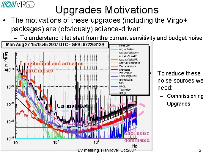
Upgrades Motivations • The motivations of these upgrades (including the Virgo+ packages) are (obviously) science-driven – To understand it let start from the current sensitivity and budget noise Longitudinal and actuation control noises • To reduce these noise sources we need: – Commissioning – Upgrades Un-modeled Shot noise dominated LV meeting, Hannover Oct 2007 2
Proposed strategy • Virgo+ needs a series of preliminary upgrades interlaced with the commissioning activity – Coil drivers, thermal compensation, fast centering quadrant PHD, … • Part of them are described in the Virgo commissioning talk • The Virgo+ upgrade strategy should respect the following – Aim: • To maximize the detection probability – To maximize the coincidences with e. LIGO – Constrains: • Need of an intense and “enough long” commissioning after VSR 1 to understand the low-medium frequency noise of Virgo • Have an enough long (~1 year) post-upgrade commissioning period • Be back in science mode in (middle) 2009 • Have a Virgo+ sensitivity comparable with e. LIGO in a wide frequency range LV meeting, Hannover Oct 2007 3
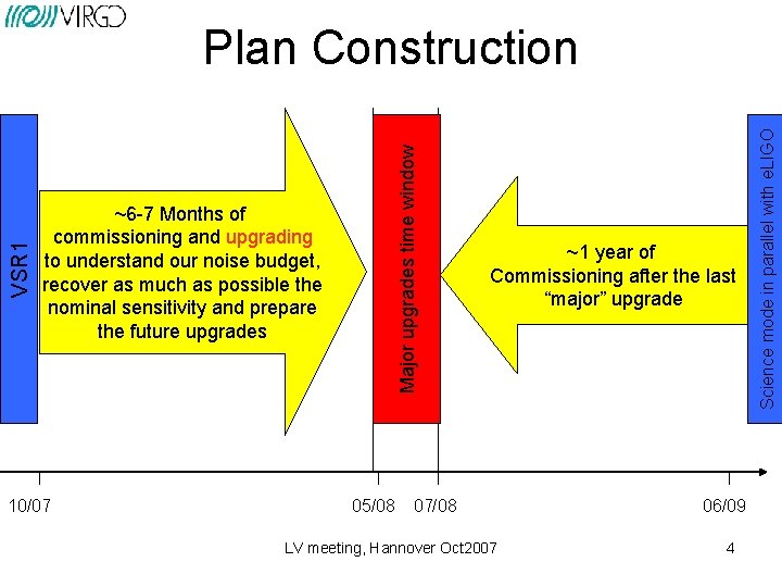
~6 -7 Months of commissioning and upgrading to understand our noise budget, recover as much as possible the nominal sensitivity and prepare the future upgrades 10/07 05/08 ~1 year of Commissioning after the last “major” upgrade 07/08 LV meeting, Hannover Oct 2007 06/09 4 Science mode in parallel with e. LIGO Major upgrades time window VSR 1 Plan Construction

Post VSR 1 -Commissioning (2007 -early 2008) • Aim – Understanding the machine and reduce the noises that could affect the designed Virgo+ upgrades • Foreseen activities: – See Edwige’s talk LV meeting, Hannover Oct 2007 5
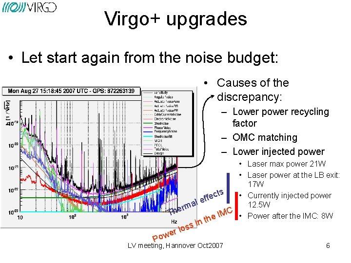
Virgo+ upgrades • Let start again from the noise budget: • Causes of the discrepancy: – Lower power recycling factor – OMC matching – Lower injected power • Laser max power 21 W • Laser power at the LB exit: 17 W cts • Currently injected power e f f e al 12. 5 W m r e C Th e IM • Power after the IMC: 8 W h t in s s r lo e w Po LV meeting, Hannover Oct 2007 6
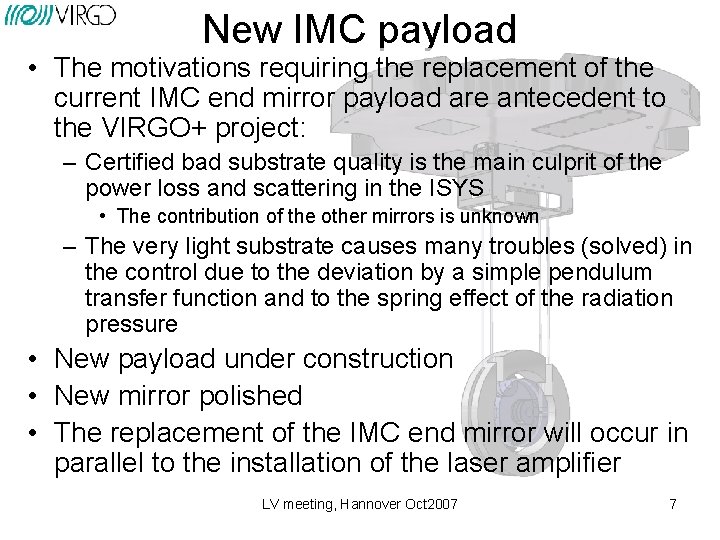
New IMC payload • The motivations requiring the replacement of the current IMC end mirror payload are antecedent to the VIRGO+ project: – Certified bad substrate quality is the main culprit of the power loss and scattering in the ISYS • The contribution of the other mirrors is unknown – The very light substrate causes many troubles (solved) in the control due to the deviation by a simple pendulum transfer function and to the spring effect of the radiation pressure • New payload under construction • New mirror polished • The replacement of the IMC end mirror will occur in parallel to the installation of the laser amplifier LV meeting, Hannover Oct 2007 7
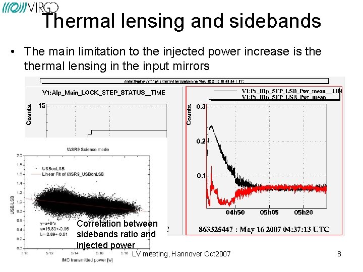
Thermal lensing and sidebands • The main limitation to the injected power increase is thermal lensing in the input mirrors Correlation between sidebands ratio and injected power LV meeting, Hannover Oct 2007 8
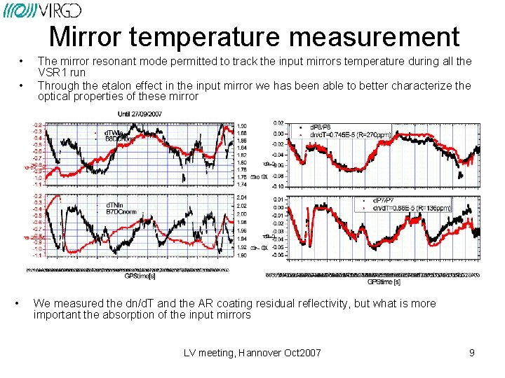
Mirror temperature measurement • • • The mirror resonant mode permitted to track the input mirrors temperature during all the VSR 1 run Through the etalon effect in the input mirror we has been able to better characterize the optical properties of these mirror We measured the dn/d. T and the AR coating residual reflectivity, but what is more important the absorption of the input mirrors LV meeting, Hannover Oct 2007 9
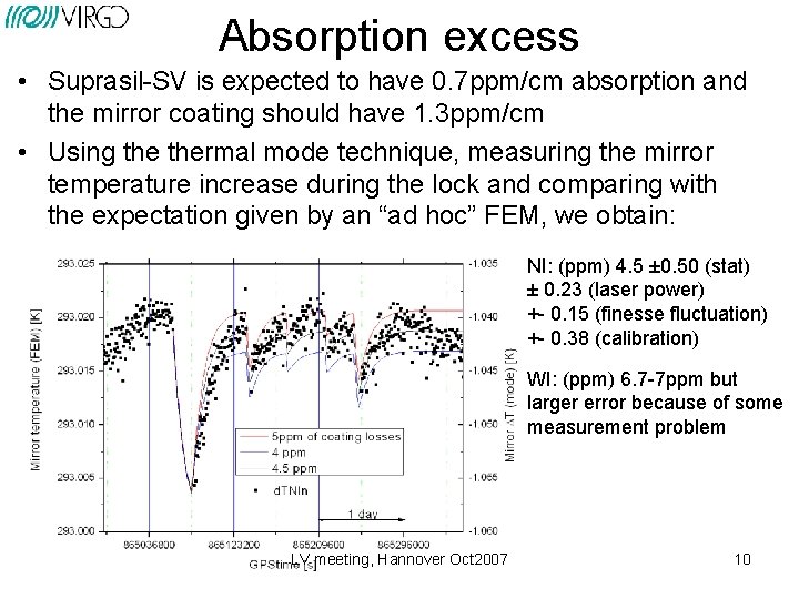
Absorption excess • Suprasil-SV is expected to have 0. 7 ppm/cm absorption and the mirror coating should have 1. 3 ppm/cm • Using thermal mode technique, measuring the mirror temperature increase during the lock and comparing with the expectation given by an “ad hoc” FEM, we obtain: NI: (ppm) 4. 5 ± 0. 50 (stat) ± 0. 23 (laser power) +- 0. 15 (finesse fluctuation) +- 0. 38 (calibration) WI: (ppm) 6. 7 -7 ppm but larger error because of some measurement problem LV meeting, Hannover Oct 2007 10
Thermal lensing mitigation • The first action to reduce thermal lensing is the reduction of the absorbed power: – Input mirror cleaning • Under preparation with the experts – Cleaning attempt using commercial cleaning polymer (end of Nov) – “Final solution”: TCS (Thermal compensation system) • Solution already adopted in LIGO – Similar principle, but original implementation because of different geometry – Implementation expected in Feb-Mar 2008 • Error signal generation – Use a pin-hole mirror and a couple of PHD – Implementation expected before the end of 2007 LV meeting, Hannover Oct 2007 11
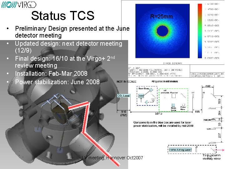
Status TCS R=25 mm • Preliminary Design presented at the June detector meeting • Updated design: next detector meeting (12/9) • Final design: 16/10 at the Virgo+ 2 nd review meeting • Installation: Feb-Mar 2008 • Power stabilization: June 2008 LV meeting, Hannover Oct 2007 12
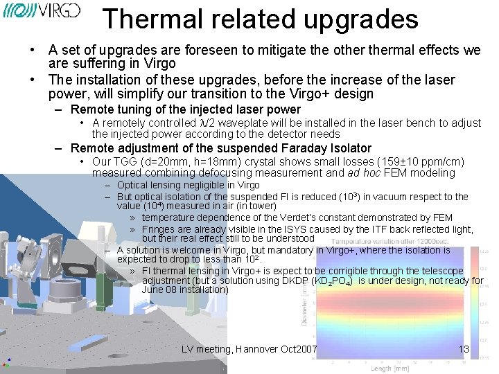
Thermal related upgrades • A set of upgrades are foreseen to mitigate the othermal effects we are suffering in Virgo • The installation of these upgrades, before the increase of the laser power, will simplify our transition to the Virgo+ design – Remote tuning of the injected laser power • A remotely controlled l/2 waveplate will be installed in the laser bench to adjust the injected power according to the detector needs – Remote adjustment of the suspended Faraday Isolator • Our TGG (d=20 mm, h=18 mm) crystal shows small losses (159± 10 ppm/cm) measured combining defocusing measurement and ad hoc FEM modeling – Optical lensing negligible in Virgo – But optical isolation of the suspended FI is reduced (103) in vacuum respect to the value (104) measured in air (in tower) » temperature dependence of the Verdet’s constant demonstrated by FEM » Fringes are already visible in the ISYS caused by the ITF back reflected light, but their real effect still to be understood – A solution is welcome in Virgo, but mandatory in Virgo+, where the isolation is expected to drop to less than 102. » FI thermal lensing in Virgo+ is expect to be corrigible through the telescope adjustment (but a solution using DKDP (KD 2 PO 4) is under design, not ready for June 08 installation) LV meeting, Hannover Oct 2007 13
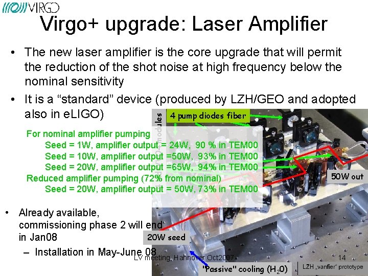
Virgo+ upgrade: Laser Amplifier 4 Nd-YVO 4 modules • The new laser amplifier is the core upgrade that will permit the reduction of the shot noise at high frequency below the nominal sensitivity • It is a “standard” device (produced by LZH/GEO and adopted also in e. LIGO) 4 pump diodes fiber For nominal amplifier pumping Seed = 1 W, amplifier output = 24 W, 90 % in TEM 00 Seed = 10 W, amplifier output =50 W, 93% in TEM 00 Seed = 20 W, amplifier output =65 W, 94% in TEM 00 Reduced amplifier pumping (72% from nominal) Seed = 20 W, amplifier output = 50 W, 73% in TEM 00 • Already available, commissioning phase 2 will end 20 W seed in Jan 08 – Installation in May-June 08 LV meeting, Hannover Oct 2007 "Passive" cooling (H 20) 50 W out 14
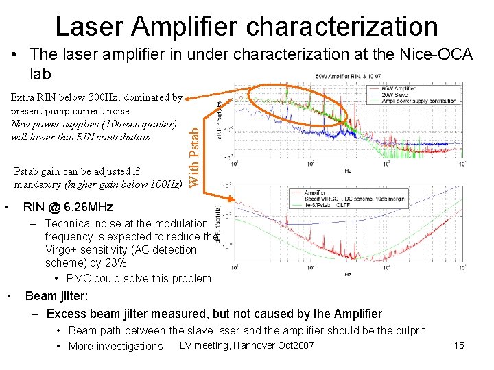
Laser Amplifier characterization Extra RIN below 300 Hz, dominated by present pump current noise New power supplies (10 times quieter) will lower this RIN contribution Pstab gain can be adjusted if mandatory (higher gain below 100 Hz) • With Pstab • The laser amplifier in under characterization at the Nice-OCA lab RIN @ 6. 26 MHz – Technical noise at the modulation frequency is expected to reduce the Virgo+ sensitivity (AC detection scheme) by 23% • PMC could solve this problem • Beam jitter: – Excess beam jitter measured, but not caused by the Amplifier • Beam path between the slave laser and the amplifier should be the culprit • More investigations LV meeting, Hannover Oct 2007 15
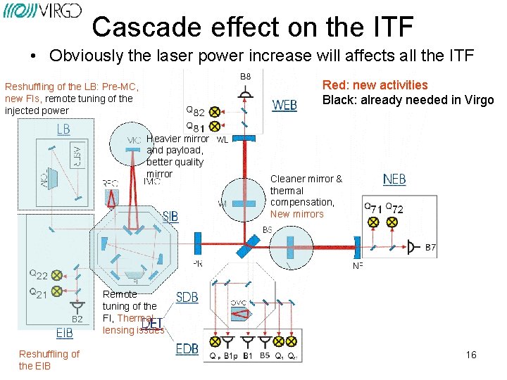
Cascade effect on the ITF • Obviously the laser power increase will affects all the ITF Red: new activities Black: already needed in Virgo Reshuffling of the LB: Pre-MC, new FIs, remote tuning of the injected power Heavier mirror and payload, better quality mirror Cleaner mirror & thermal compensation, New mirrors Remote tuning of the FI, Thermal lensing issues Reshuffling of the EIB 16
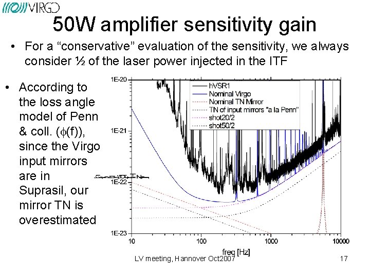
50 W amplifier sensitivity gain • For a “conservative” evaluation of the sensitivity, we always consider ½ of the laser power injected in the ITF • According to the loss angle model of Penn & coll. (f(f)), since the Virgo input mirrors are in Suprasil, our mirror TN is overestimated LV meeting, Hannover Oct 2007 17
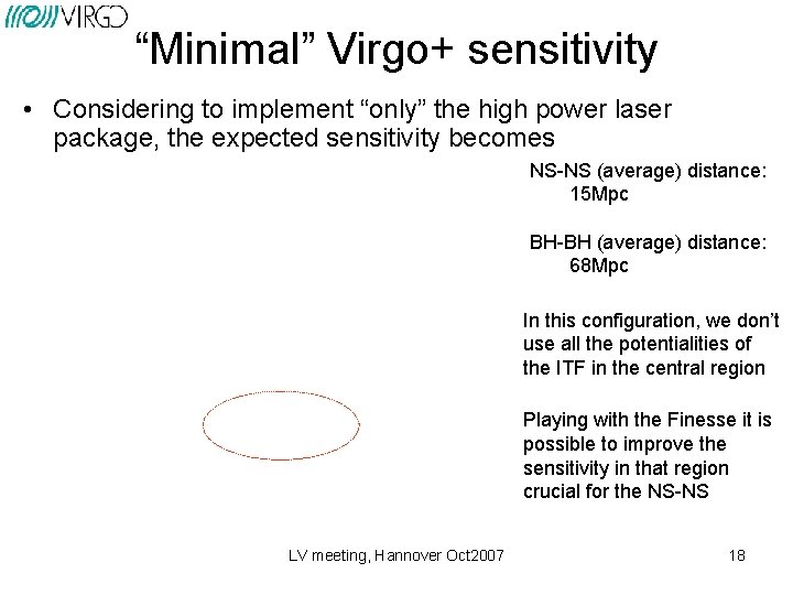
“Minimal” Virgo+ sensitivity • Considering to implement “only” the high power laser package, the expected sensitivity becomes NS-NS (average) distance: 15 Mpc BH-BH (average) distance: 68 Mpc In this configuration, we don’t use all the potentialities of the ITF in the central region Playing with the Finesse it is possible to improve the sensitivity in that region crucial for the NS-NS LV meeting, Hannover Oct 2007 18
New mirrors… a list of motivations • Current mirrors are probably polluted by the installation procedure and a cleaning operation, effected in tower, probably will not recover the full performances – The new mirrors could be delivered with the protection film, to be removed at the end of the installation • The magnets in the input mirror are mounted with parallel polarity, meanwhile the minimization of the magnetic dipole requires pairs with anti-parallel orientation. Furthermore the magnets are a factor 5 more intense of the original design and this increase the coupling with the environmental magnetic noise LV meeting, Hannover Oct 2007 19
New mirrors… a list of motivations • The end mirrors have no anti-reflecting coating in the back face. This causes (measured) multiple beam scattering in the end benches. • Replacing the input mirrors we can increase the reflectivity up to R=95. 9% to obtain a Finesse of 150 and largely improving the sensitivity • Replacing the end mirrors we can use Suprasil-SV to further reduce thermal noise (and cure the AR coating absence) • Replacing all the mirrors we can – have mirrors with a better flatness (source of scattering and losses, according to the simulation) – Use the new Ti doped coating for a further TN reduction LV meeting, Hannover Oct 2007 20
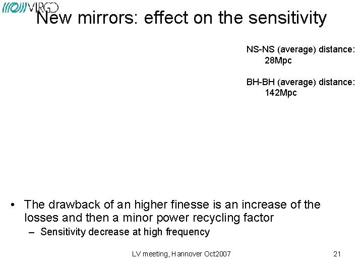
New mirrors: effect on the sensitivity NS-NS (average) distance: 28 Mpc BH-BH (average) distance: 142 Mpc • The drawback of an higher finesse is an increase of the losses and then a minor power recycling factor – Sensitivity decrease at high frequency LV meeting, Hannover Oct 2007 21
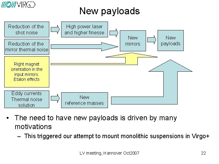
New payloads Reduction of the shot noise High power laser and higher finesse Reduction of the mirror thermal noise New mirrors New payloads Right magnet orientation in the input mirrors. Etalon effects Eddy currents Thermal noise solution New reference masses • The need to have new payloads is driven by many motivations – This triggered our attempt to mount monolithic suspensions in Virgo+ LV meeting, Hannover Oct 2007 22
Virgo+ upgrade: monolithic suspensions • Monolithic fused silica suspension development is still an heavy activity in Virgo but the engineering of the solution is still far – Incompatible with the May 2008 shutdown and mainly with the June 2009 data taking • The replacement of the current payloads with ameliorated standard steel solution is still an open possibility – Decision (I hope) soon LV meeting, Hannover Oct 2007 23
Control & DAQ electronics • • New DSP development in Pisa (important for the low frequency part), and a series of upgrades of the DAQ electronics has been foreseen and supported by EGO Design activity progressing in Annecy: – Development of new timing system (obsolescence of the hardware) • GPS receiver/signal generator (tested, patched and ready; more boxes to be purchased) • TDBox (Timing distribution box): design ready for production • MUX/De. MUX: router for the optical links between TOLM and ADC boards. Prototype available. Production and tests on September-October 2007 • TOLM: A prototype available and used for ADC tests, TOLM /DSP interface tested. Two versions expected to be produced: PMC and PCI 64 formats. Production expected for the March 2008. – ADC: ADC selection done (AD 7674 18 bit @ 800 k. Hz); 16 differentials channels with analog anti-alias filter at 400 KHz. Digital anti-alias filters in embedded DSPs( 4 channels per DSP ADPS-21262 @150 MHz ) Several production steps foreseen, but final production expected to end in March-April 2008. – Use of regular PCs: Tests have shown that the main Virgo control loop (photodiode readout and global control) could run up to 40 KHz on a commercial PC running a real time version of Linux. This will provide more computing resource for various control loops (global and local). • Installation: – Expected in May 2008 -July 2008 LV meeting, Hannover Oct 2007 24
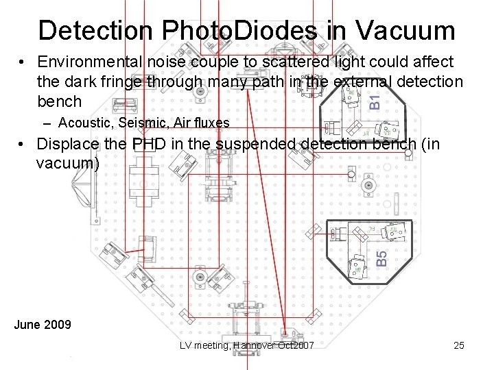
Detection Photo. Diodes in Vacuum • Environmental noise couple to scattered light could affect the dark fringe through many path in the external detection bench – Acoustic, Seismic, Air fluxes • Displace the PHD in the suspended detection bench (in vacuum) June 2009 LV meeting, Hannover Oct 2007 25
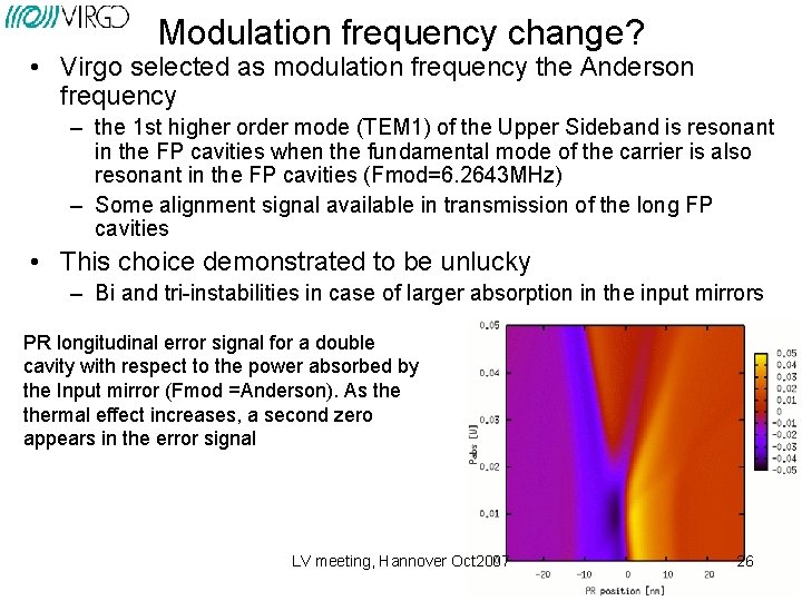
Modulation frequency change? • Virgo selected as modulation frequency the Anderson frequency – the 1 st higher order mode (TEM 1) of the Upper Sideband is resonant in the FP cavities when the fundamental mode of the carrier is also resonant in the FP cavities (Fmod=6. 2643 MHz) – Some alignment signal available in transmission of the long FP cavities • This choice demonstrated to be unlucky – Bi and tri-instabilities in case of larger absorption in the input mirrors PR longitudinal error signal for a double cavity with respect to the power absorbed by the Input mirror (Fmod =Anderson). As thermal effect increases, a second zero appears in the error signal LV meeting, Hannover Oct 2007 26
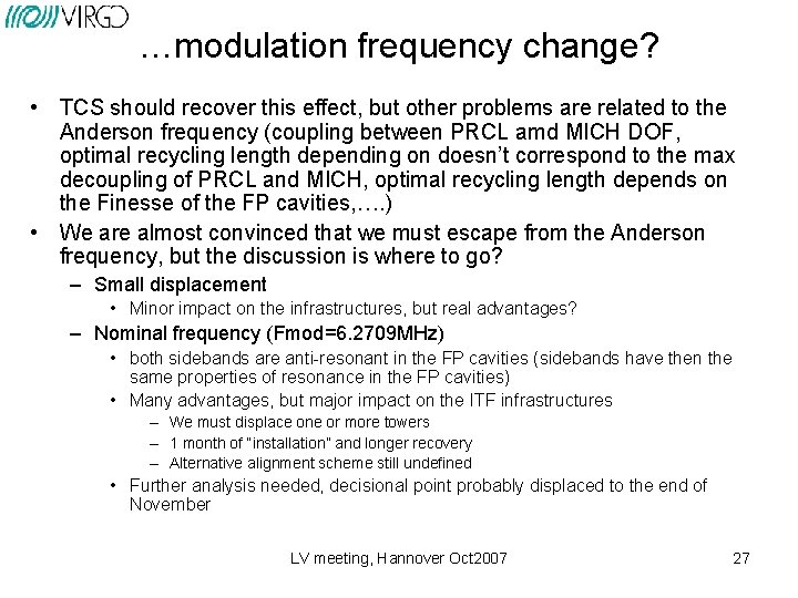
…modulation frequency change? • TCS should recover this effect, but other problems are related to the Anderson frequency (coupling between PRCL amd MICH DOF, optimal recycling length depending on doesn’t correspond to the max decoupling of PRCL and MICH, optimal recycling length depends on the Finesse of the FP cavities, …. ) • We are almost convinced that we must escape from the Anderson frequency, but the discussion is where to go? – Small displacement • Minor impact on the infrastructures, but real advantages? – Nominal frequency (Fmod=6. 2709 MHz) • both sidebands are anti-resonant in the FP cavities (sidebands have then the same properties of resonance in the FP cavities) • Many advantages, but major impact on the ITF infrastructures – We must displace one or more towers – 1 month of “installation” and longer recovery – Alternative alignment scheme still undefined • Further analysis needed, decisional point probably displaced to the end of November LV meeting, Hannover Oct 2007 27
Planning LV meeting, Hannover Oct 2007
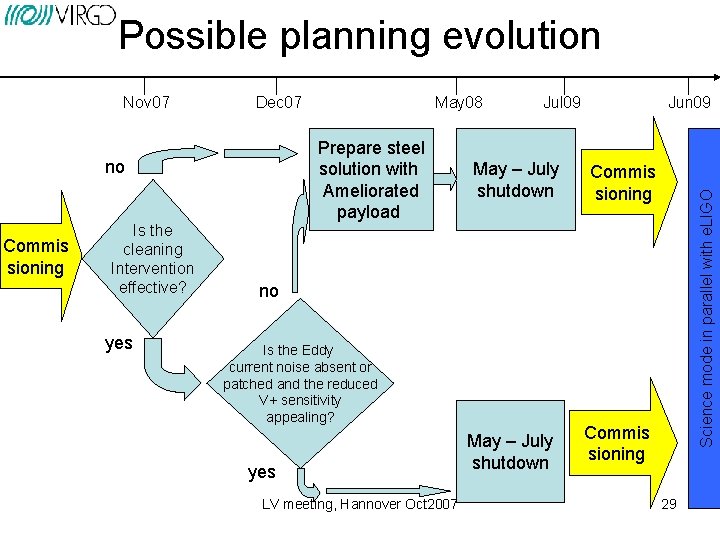
Possible planning evolution Dec 07 Prepare steel solution with Ameliorated payload no Commis sioning Is the cleaning Intervention effective? yes May 08 Jul 09 May – July shutdown Jun 09 Commis sioning Science mode in parallel with e. LIGO Nov 07 no Is the Eddy current noise absent or patched and the reduced V+ sensitivity appealing? yes LV meeting, Hannover Oct 2007 May – July shutdown Commis sioning 29
- Slides: 29