
ViewCasting Viewbased Stream Dissemination and Control for Multi
View-Casting: View-based Stream Dissemination and Control for Multi. Party 3 D Tele-immersive Environments Klara Nahrstedt University of Illinois at Urbana-Champaign Joint work with UC Berkeley: Prof. Ruzena Bajcsy, Dr. Gregorij Kurillov, Dr. Sang-Jung Hack (3 D Video) Illinois: Dr. Zhenyu Yang, Dr. Bin Yu, Dr. Jin Liang, Dr. Yi Cui , Wanmin Wu (Qo. S Management), NAIST Japan: Dr. Morihiko Tamai, Prof. Keiichi Yasumoto (Wii Interfaces), UC Berkeley/Illinois: Lisa Wymore, Renata Sheppard (Dance Choreography)
Outline l l l Motivation and Goals Challenges TEEVE Solution Details l l View Concept View Casting: view selection, forest-casting, BW allocation, delay-sensitive streaming Experimental Results Conclusion
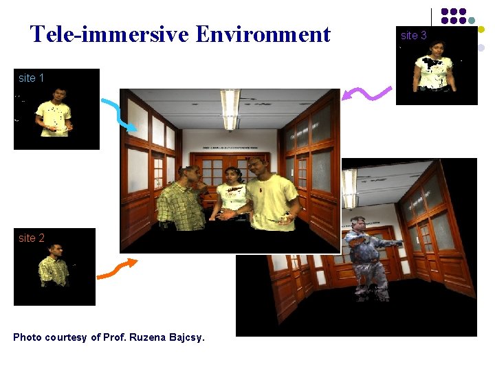
Tele-immersive Environment site 1 site 2 Photo courtesy of Prof. Ruzena Bajcsy. site 3
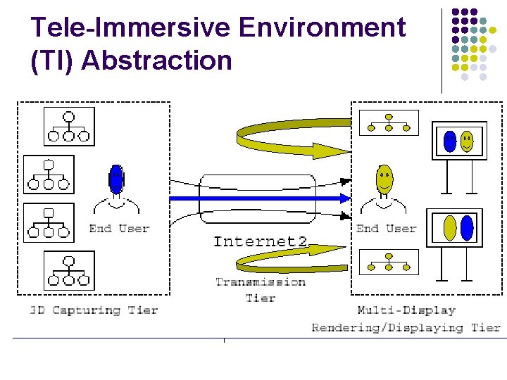
Tele-Immersive Environment (TI) Abstraction
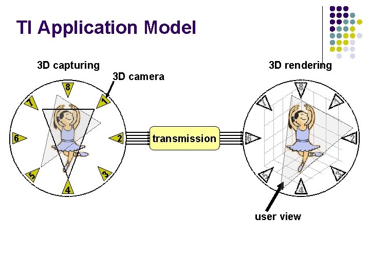
TI Application Model 3 D camera 7 5 3 2 4 transmission 6 2 3 7 6 1 8 3 D rendering 5 3 D capturing 4 user view
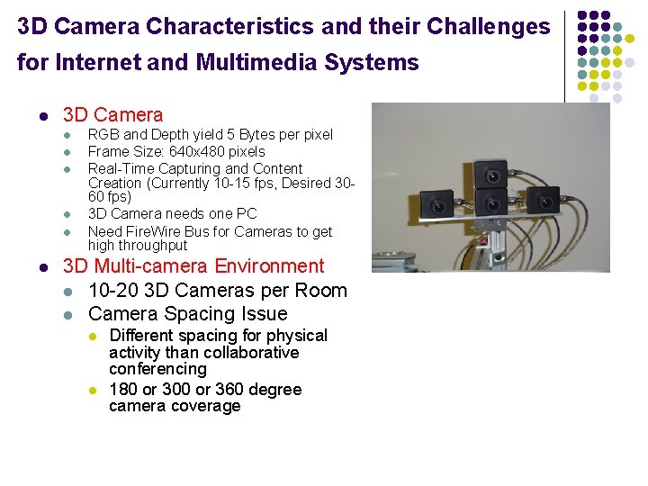
3 D Camera Characteristics and their Challenges for Internet and Multimedia Systems l 3 D Camera l l l RGB and Depth yield 5 Bytes per pixel Frame Size: 640 x 480 pixels Real-Time Capturing and Content Creation (Currently 10 -15 fps, Desired 3060 fps) 3 D Camera needs one PC Need Fire. Wire Bus for Cameras to get high throughput 3 D Multi-camera Environment l 10 -20 3 D Cameras per Room l Camera Spacing Issue l l Different spacing for physical activity than collaborative conferencing 180 or 300 or 360 degree camera coverage
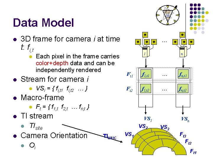
Data Model l 3 D frame for camera i at time t: fi, t l l Stream for camera i l l n Ft 1 f 1, t 1 … fn, t 1 Ft 2 f 1, t 2 … fn, t 2 Ft = { f 1, t f 2, t … fn, t } TI stream l l VSi = { fi, t 1 fi, t 2 … } 1 Macro-frame l l Each pixel in the frame carries color+depth data and can be independently rendered … TIsite Camera Orientation l VS 1 VS 2 Oi TIUIUC VS 1 VSn VS 3 Ft 2 Ft 1
Implications: 4 D Content Challenge l Deal with l Huge TI Frame Size Ft l l TI Frame rate l l l One 3 D stream Si: 640 x 480 (pixels/frame) x 5 (bytes/pixel) x 15 (frames/sec) = 23, 040, 000 bytes/second (approx. 23 MBytes/sec) = 184 Mbps One TI stream TIroom (e. g. , 10 3 D Streams): 230, 040, 000 bytes/sec (approx. 230 MBytes/sec = 1. 84 Gpbs) If we increase frame-rate, explosion of bandwidth !!!!! Slow 3 D Reconstruction, 3 D Modeling, 3 D Rendering l l Applications desire from 15 -60 Macro-frames per second Huge bandwidth uncompressed l l Macro-frame (e. g. , 10 3 D Frames in one time instance) 71 ms per frame in 3 D reconstruction, … Need 3 D Compression Need Parallel Processing
Multi-Party 3 D Tele-Immersive System D C D G C UC Berkeley C G C D C G D C UIUC D D G G service gateway D display C camera
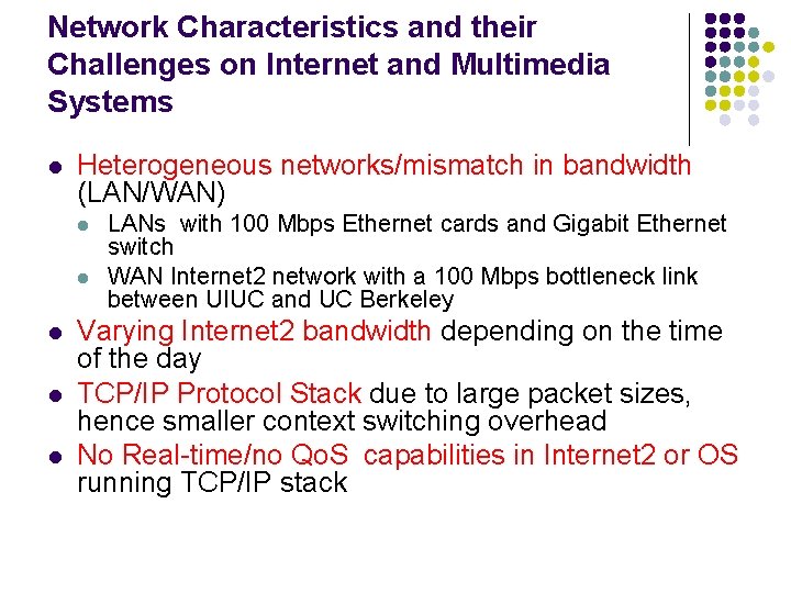
Network Characteristics and their Challenges on Internet and Multimedia Systems l Heterogeneous networks/mismatch in bandwidth (LAN/WAN) l l l LANs with 100 Mbps Ethernet cards and Gigabit Ethernet switch WAN Internet 2 network with a 100 Mbps bottleneck link between UIUC and UC Berkeley Varying Internet 2 bandwidth depending on the time of the day TCP/IP Protocol Stack due to large packet sizes, hence smaller context switching overhead No Real-time/no Qo. S capabilities in Internet 2 or OS running TCP/IP stack
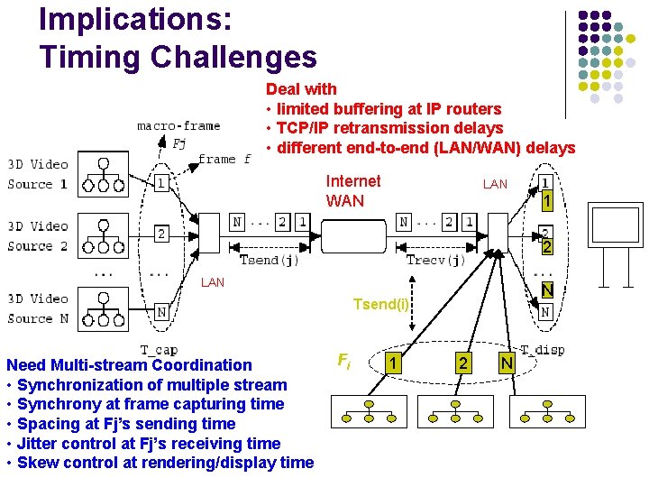
Implications: Timing Challenges Deal with • limited buffering at IP routers • TCP/IP retransmission delays • different end-to-end (LAN/WAN) delays Internet WAN LAN 1 2 LAN N Tsend(i) Need Multi-stream Coordination • Synchronization of multiple stream • Synchrony at frame capturing time • Spacing at Fj’s sending time • Jitter control at Fj’s receiving time • Skew control at rendering/display time Fi 1 2 N
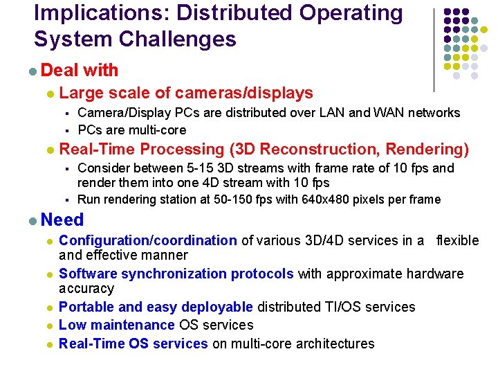
Implications: Distributed Operating System Challenges l Deal with l Large scale of cameras/displays § § l Camera/Display PCs are distributed over LAN and WAN networks PCs are multi-core Real-Time Processing (3 D Reconstruction, Rendering) § Consider between 5 -15 3 D streams with frame rate of 10 fps and render them into one 4 D stream with 10 fps § Run rendering station at 50 -150 fps with 640 x 480 pixels per frame l Need l l l Configuration/coordination of various 3 D/4 D services in a flexible and effective manner Software synchronization protocols with approximate hardware accuracy Portable and easy deployable distributed TI/OS services Low maintenance OS services Real-Time OS services on multi-core architectures
Implications: Networking Challenges l Deal with l Large Bandwidth Demand § § l One 3 D stream: 23 MBytes/sec One TI (e. g. , 10 3 D Streams): 230 MBytes/sec) Real-Time Communication for Interactivity § 80 -100 millisecond interactive delay l Need l Multi-stream Coordination § due to large bursts at routers, need packet spacing Smart Delay/Bandwidth Management over Best Effort Internet l Synchronization of Multiple Streams l § l need to send all streams within a constrained time interval so that rendered frame can be done in timely fashion Dealing with Scale § multi-party / many-to-many multicast forest protocols (camera arrays, participants, microphone arrays, …)
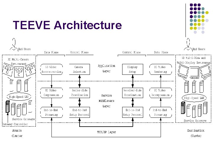
TEEVE Architecture
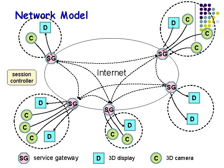
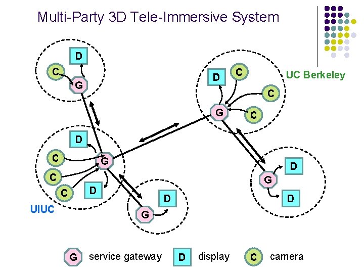
Network Model D D C C SG SG Internet session controller SG D D SG SG C D D C C C D SG service gateway D C 3 D display C 3 D camera
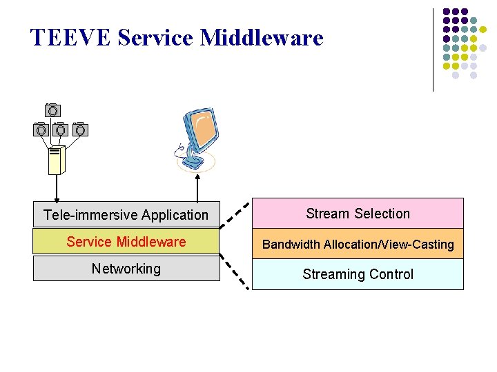
TEEVE Service Middleware Tele-immersive Application Stream Selection Service Middleware Bandwidth Allocation/View-Casting Networking Streaming Control
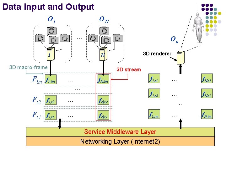
Data Input and Output O 1 ON … 1 Ou 3 D macro-frame Ftm f 1, tm 3 D renderer N 3 D stream f. N, tm … … Ft 2 f 1, t 2 … f. N, t 2 Ft 1 f 1, t 1 … f. N, t 1 f 1, t 2 … f. N, t 2 … f 1, tm Service Middleware Layer Networking Layer (Internet 2) … f. N, tm
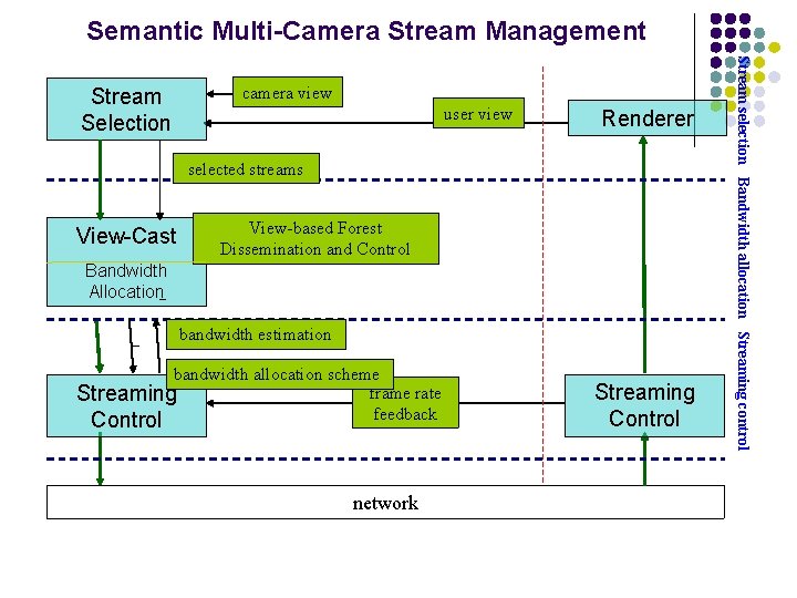
Semantic Multi-Camera Stream Management camera view user view Renderer selected streams View-Cast View-based Forest Dissemination and Control Bandwidth Allocation bandwidth estimation bandwidth allocation scheme frame rate Streaming feedback Control network Streaming Control Stream selection Bandwidth allocation Streaming control Stream Selection
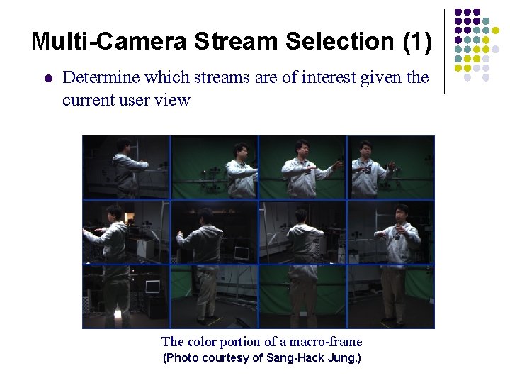
Multi-Camera Stream Selection (1) l Determine which streams are of interest given the current user view The color portion of a macro-frame (Photo courtesy of Sang-Hack Jung. )
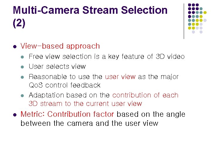
Multi-Camera Stream Selection (2) l View-based approach l l l Free view selection is a key feature of 3 D video User selects view Reasonable to use the user view as the major Qo. S control feedback Adaptation based on the contribution of each 3 D stream to the current user view Metric: Contribution factor based on the angle between the camera and the user view
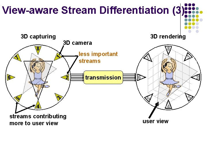
View-aware Stream Differentiation (3) 3 D camera 4 streams contributing more to user view transmission 1 6 2 3 5 3 2 7 7 6 8 less important streams 1 8 3 D rendering 5 3 D capturing 4 user view
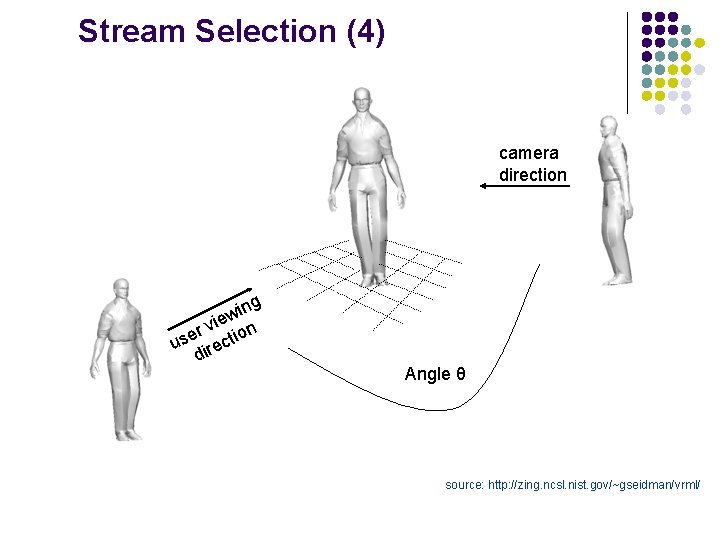
Stream Selection (4) camera direction ing w vie on r use irecti d Angle θ source: http: //zing. ncsl. nist. gov/~gseidman/vrml/
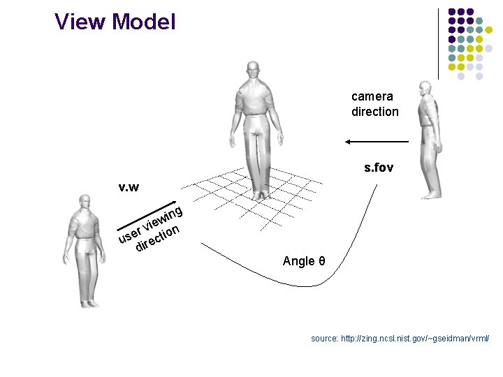
View Model camera direction s. fov v. w ing w vie on r use irecti d Angle θ source: http: //zing. ncsl. nist. gov/~gseidman/vrml/
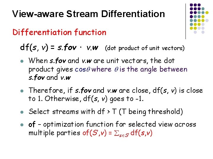
View-aware Stream Differentiation function df(s, v) = s. fov · v. w l l (dot product of unit vectors) When s. fov and v. w are unit vectors, the dot product gives cos where is the angle between s. fov and v. w Therefore, if s. fov and v. w are close, df(s, v) is close to 1. Otherwise, df(s, v) goes to -1. Select streams with df > T (T being threshold) of – optimization function for selected view across multiple parties of(S’, v) = s S’ df(s, v)
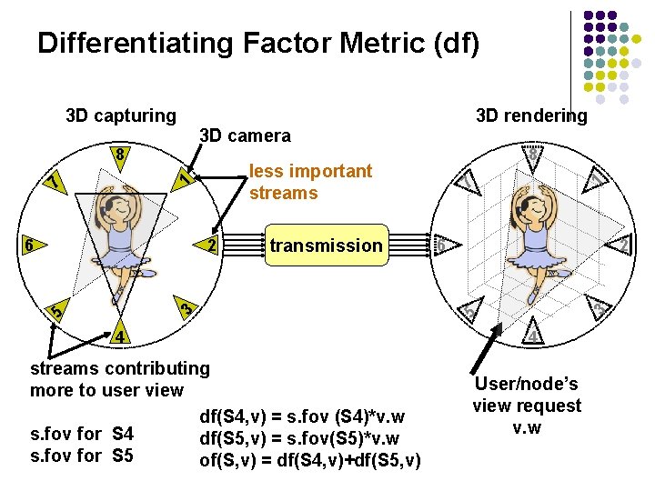
Differentiating Factor Metric (df) 3 D camera 5 4 streams contributing more to user view df(S 4, v) = s. fov (S 4)*v. w s. fov for S 4 df(S 5, v) = s. fov(S 5)*v. w s. fov for S 5 of(S, v) = df(S 4, v)+df(S 5, v) 1 6 2 3 transmission 3 2 7 7 6 8 less important streams 1 8 3 D rendering 5 3 D capturing 4 User/node’s view request v. w
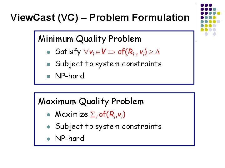
View. Cast (VC) – Problem Formulation Minimum Quality Problem l Satisfy vi V of(Ri , vi) l Subject to system constraints l NP-hard Maximum Quality Problem l Maximize i of(Ri, vi) l Subject to system constraints l NP-hard
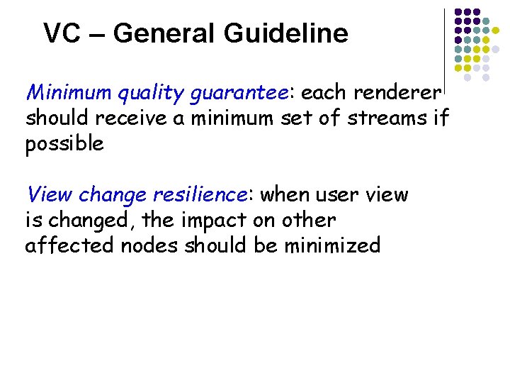
VC – General Guideline Minimum quality guarantee: each renderer should receive a minimum set of streams if possible View change resilience: when user view is changed, the impact on other affected nodes should be minimized
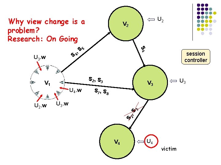
Why view change is a problem? Research: On Going S 2, S 3 V 1 U 4. w session controller U 3 V 3 S 7, S 8 2 , S 3 U 3. w S U 2. w 5 S 4 S U 3. w , S 4 U 2 V 4 U 4 victim
Bandwidth Allocation (1) VS 1 VS 2 VSi VSj VSN fs … stream … selection … A 1 fs bandwidth allocation fs Ai' Am TFS quality
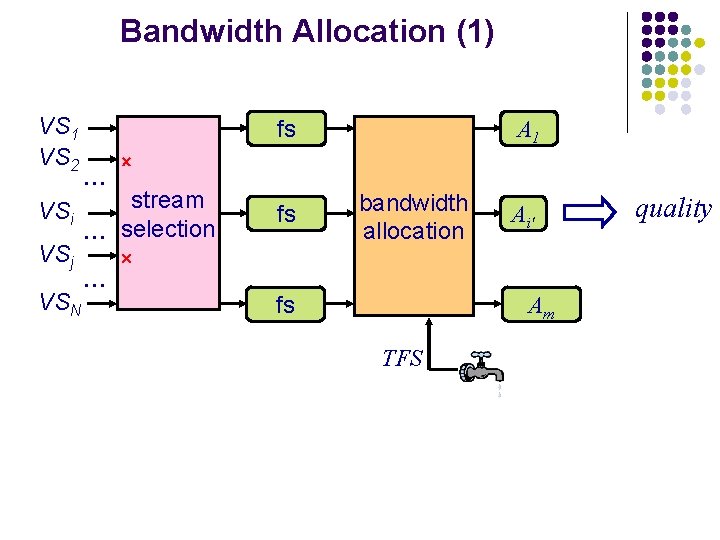
Bandwidth Allocation (2) l Frame size allocation l l l TFS : target macro-frame size estimated by the underlying streaming control Given macro-frame Ft and TFS, allocate the frame size (Ai) for each frame (fi, t) Priority scheme based on CF
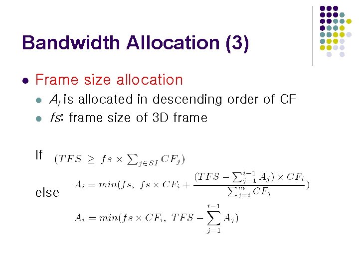
Bandwidth Allocation (3) l Frame size allocation l l Ai is allocated in descending order of CF fs: frame size of 3 D frame If else
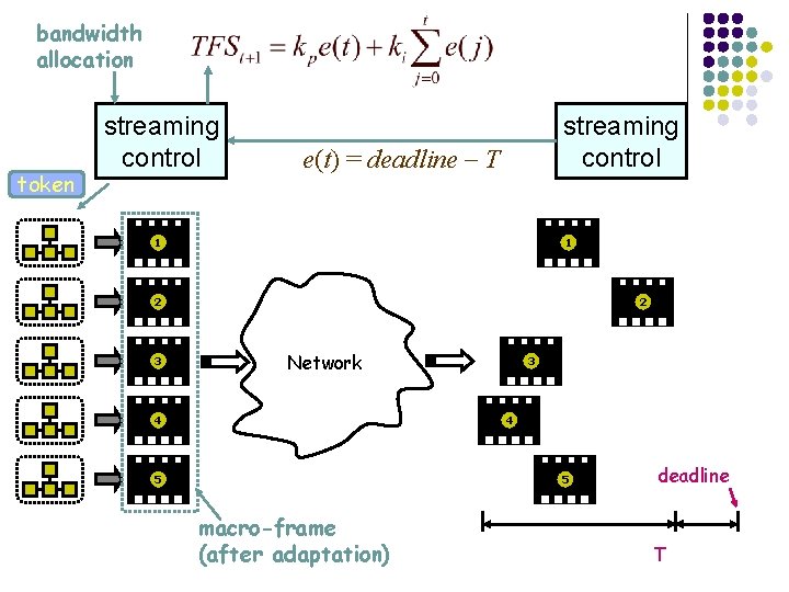
Streaming Control (1) l Basic end-to-end protocol l l sender l receives bandwidth allocation l generates token = ((VS 1 , A 1), (VS 2 , A 2), …, (VSN , AN)) l passes token along camera clusters receiver l maintains periodic timer for rendering at fixed interval l monitors the deadline of each macro-frame l when the last frame of current macro-frame received at T § calculate the difference between T and deadline § send the difference back to sender
bandwidth allocation token streaming control e(t) = deadline T 1 1 2 3 2 Network 4 3 4 5 5 macro-frame (after adaptation) deadline T
Experimental Examples of Tele -immersive Environments TI in UIUC (Prof. Nahrstedt) TI in UC Berkeley (Prof. Bajcsy) Internet 2
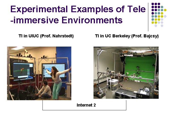
Experimental Setup (TEEVE) l Metrics: l l l Experimental parameters of remote testbed l l l Overall throughput of macro-frame Fj Completion time interval for macro-frame Fj Individual throughput of stream i End-to-end Delay of a macro-frame Fj Number of sender gateways 2 Number of receiver gateways 2 Number of 3 D streams 12 UIUC-UCB Equipment l l Dell precision 450 (Dual Xeon processor with 1 GBytes memory), running Fedora Core 2 LAN 100 Mbps and Internet 2 between UCB and UIUC
Timing Performance Validation Macro-frame Completion Interval at the receiver side Macro-Frame Delay (End-to-end Delay – UIUC/UCB)
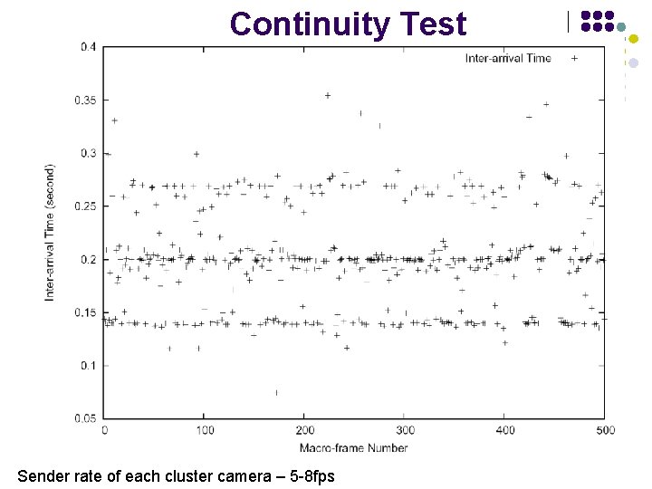
Continuity Test Sender rate of each cluster camera – 5 -8 fps
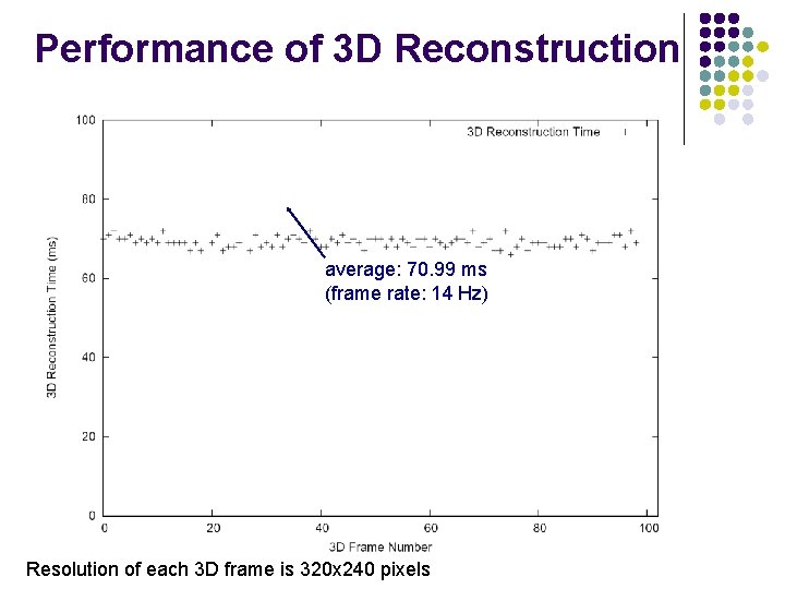
Performance of 3 D Reconstruction average: 70. 99 ms (frame rate: 14 Hz) Resolution of each 3 D frame is 320 x 240 pixels
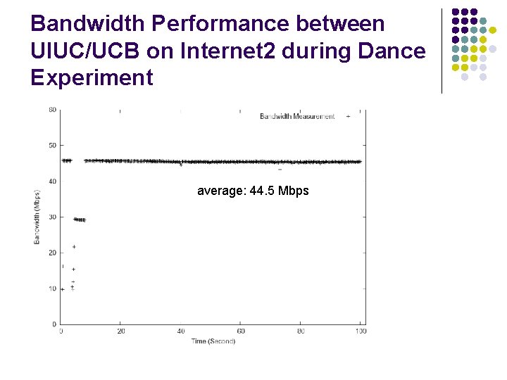
Bandwidth Performance between UIUC/UCB on Internet 2 during Dance Experiment average: 44. 5 Mbps
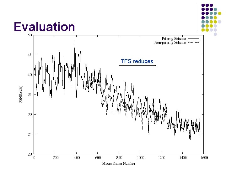
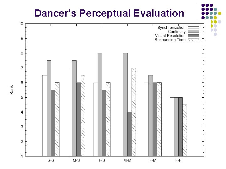
Evaluation TFS reduces
Dancer’s Perceptual Evaluation
Experiment Setup Simulated 3 DTI session topology mesh (connected) # of vertices (n) 5, 6, …, 10 # of edges (CR) 25%, 50%, 75%, 100% ( n (n-1)) degree bound (Ii, Oi) 12, 24, 36 streams/vertex (|Si|) 8 max. streams/view 4 simulation time 200 minutes view change interval normal distribution ( = 60 s, = 10 s) view change pattern (a) random walk with average degree change of 30 , (b) Zipf (n = 10) delay bound (B) 200 ms edge delay normal distribution ( = 80 ms, = 20 ms)
Experiment Setup Counterpart for comparison, MC–n l l A multicast-based scheme where n streams (n =1, 2, 3, or 4) must be retrieved to serve a view. Otherwise, the view request is rejected. No preemption.
Rejection Ratio CR = 100%, Ii (Oi) = 12 MC– 4 MC– 3 MC– 2 MC– 1 VC
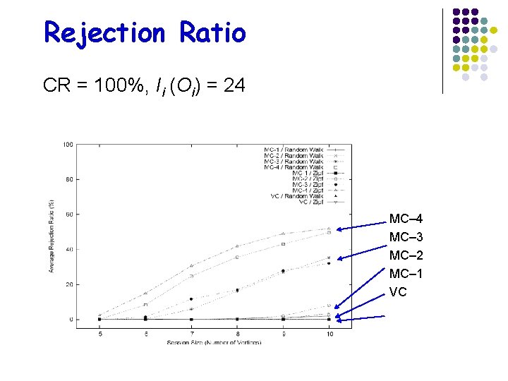
Rejection Ratio CR = 100%, Ii (Oi) = 24 MC– 3 MC– 2 MC– 1 VC
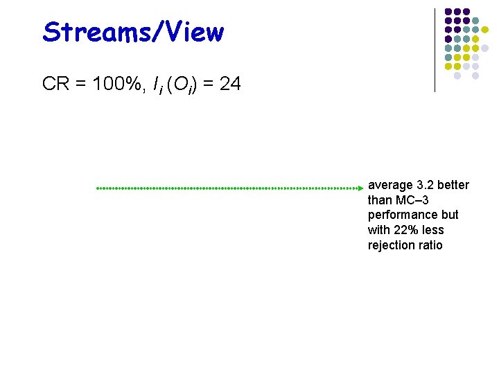
Streams/View CR = 100%, Ii (Oi) = 24 average 3. 2 better than MC– 3 performance but with 22% less rejection ratio
Conclusion l l Question: Shall we dance …. across thousands of miles? Answer: We can waltz, but not tango yet!!!
References l l l Z. Yang, K. Nahrstedt, Y. Cui, B. Yu, J. Liang, S-J. Hack, R. Bajcsy “ TEEVE: The Next Generation Architecture for Teleimmersive Environments”, IEEE International Symposium on Multimedia (ISM 2005), Irvine, CA, 2005 Z. Yang, B. Yu, K. Nahrstedt, R. Bajcsy “ A Multi-stream Adaptation Framework for Bandwidth Management in 3 D Tele -Immersion”, ACM International Workshop on Network and Operating Systems Support for Digital Audio and Video (NOSSDAV 2006), New York, NY, 2006 M. Tamai, W. Wu, K. Nahrstedt, K. Yasumoto, “A View Control Interface for 3 D Tele-Immersive Environments”, IEEE International Conference on Multimedia and Expo (ICME 2008), Hannover, Germany, 2008

Acknowledgement l This work is being continuously supported by the National Science Foundation
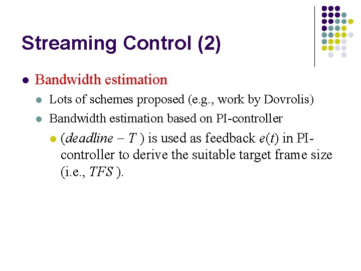
Streaming Control (2) l Bandwidth estimation l l Lots of schemes proposed (e. g. , work by Dovrolis) Bandwidth estimation based on PI-controller l (deadline T ) is used as feedback e(t) in PIcontroller to derive the suitable target frame size (i. e. , TFS ).
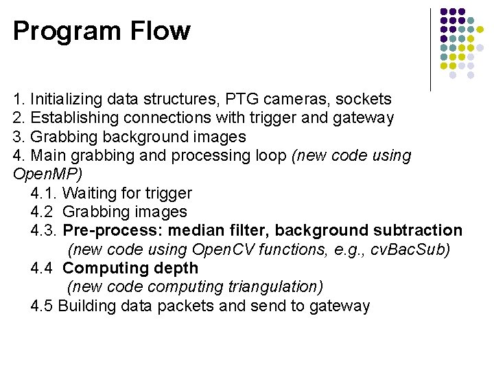
Program Flow 1. Initializing data structures, PTG cameras, sockets 2. Establishing connections with trigger and gateway 3. Grabbing background images 4. Main grabbing and processing loop (new code using Open. MP) 4. 1. Waiting for trigger 4. 2 Grabbing images 4. 3. Pre-process: median filter, background subtraction (new code using Open. CV functions, e. g. , cv. Bac. Sub) 4. 4 Computing depth (new code computing triangulation) 4. 5 Building data packets and send to gateway
- Slides: 51