VHF Contesting Primer PVRC Contesting Seminar Fredericksburg VA

VHF Contesting Primer PVRC Contesting Seminar Fredericksburg, VA W 3 ZZ – 3/19 -20/2005

LOCATION • Clear in directions of high activity • Space Wave – EPA, NJ, NY, New England • Es - 180°-300° • Above the trees • No Noise Pollution • Alternative locations • Portable Hilltops • Rovers

STATION DESIGN Overall • Multimode Radios • HF+V/UHF Radios • Multiple Transverters • Microwaves

STATION DESIGN Receivers I • Huge Signal Disparities • Weak Signals • Relative lack of QRM

STATION DESIGN Receivers II • Adequate sensitivity • Superior strong signal handling capability • Low phase noise

STATION DESIGN Transmitters I • Enough ERP to be heard • Few pileups • Amplifiers >200 watts expensive and difficult to find

STATION DESIGN Transmitters II • 100 -200 watts • Home brew amplifiers for powers >500 w

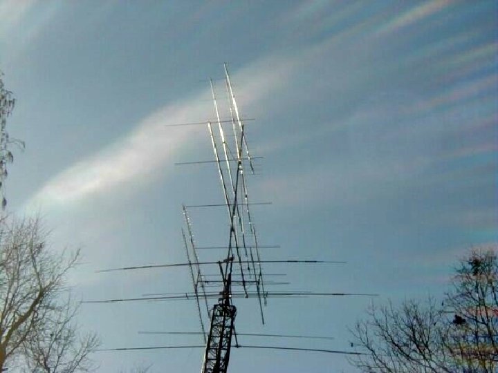
STATION DESIGN Antenna Systems I • • • Single band Very sharp patterns with few sidelobes Usually more gain than HF Ground gain unimportant except on 6 m Many λ high Low loss feedline critical

STATION DESIGN Antenna Systems II • • • Modern electrical design Reasonable mechanical design Reasonable size At least Belden 9913 F 7 or LMR 400 UF Multiband stacks

INTEGRATION BOXES • • Instant band changing Transverter selection Amplifier switching Audio distribution CW keyline distribution Microphone distribution Digital signal generation [WSJT] Remote preamp sequencers

OPERATING BASICS I • Major and minor VHF contests • • ARRL January Sweepstakes ARRL June/September QSO Parties CQ WW July VHF Contest ARRL August UHF Contest ARRL 10 GHZ Contest ARRL and DUBUS EME Contests Spring/Fall Sprints
 1296 MHz (23")
OPERATING BASICS II • Bands • Scoring 50 MHz (6 meters) 1296 MHz (23 cm) 144 MHz (2 meters) 2304 MHz (13 cm) 222 MHz (1¼ meters) 3456 MHz (9 cm) 432 MHz (70 cm) 5760 MHz (5 cm) 903 MHz (33 cm) 10 GHz (3 cm) Q points – band dependent X Multipliers – sum of grid squares per band

OPERATING BASICS III • Operating frequencies BAND RANGE CLG FREQ 50 MHz 50. 125 -. 200 50. 125 144 MHz 144. 150 -. 250 144. 200 222 MHz 222. 080 -. 130 222. 100 432 MHz 432. 080 -. 130 432. 100

OPERATING BASICS IV • Propagation • 6 meters • 2 m, 1¼ m, 70 cm • Microwaves • Common/enhanced distances • Propagation modes

OPERATING BASICS V • • Zero sum game Moving band to band Calling CQ vs S&P Other guy’s environment Band “openings” No activity between midnight and 7 a. m. Be aware of local rover routes and times

SERIOUS VHF CONTESTING • Level of competition is reasonable -Current winners the equivalent of HF little pistols • Physical location is the key • High, clear and quiet • Massive microwave station is required • A matter of integration – pieces are available commercially • Accurate pointing – digital readout • Cost is reasonable compared to high level HF contesting if you can do your own antenna work

SERIOUS RADIOS • Two identical HF IF strips • Orion, FT 1000 MP/INRAD, Elecraft K 2 • FT 9000, IC 7800 • One 2 meter/70 cm microwave IF • See above – or SDR 1000 • Transverters for 6 m through 3 cm • DEM, SSB, DB 6 NT • Amplifiers for 6 m through 3 cm • Lunar Link, DEM, DB 6 NT, surplus

SERIOUS ANTENNAS • TOWER 1 86 ft • 6 M 6 x. C 5 -50 [C 3 I] @ 30, 44, 58, 72, 86, 100’ 17. 8 d. Bi gain • TOWER 2 100 ft • 2 M 6 x. FO 12 [C 3 I] @ 52, 64, 76, 88, 100, 112’ 22. 5 d. Bi gain • TOWER 3 80 ft • 1¼M 2 x. FO 16/70 cm 2 x. FO 22 [C 3 I] [H frame] 19. 1/20. 9 d. Bi; 33 cm 2 x 3333 LY/23 cm 2 x 2445 LY [Directive Systems] [H frame] 23/24 d. Bi • TOWER 4 60 ft • 13/9 cm 6’ dish dual band feed 31/34 d. Bi; 5/3 cm 4’ dish dual band feed 35/40 d. Bi

THE BOTTOM LINE • Interesting propagation • Technical challenges • Really weak signals H a v e F U N !!
- Slides: 20