
VHDL Structures de bases Synthse doprateurs standards Prsentation
VHDL Structures de bases Synthèse d’opérateurs standards
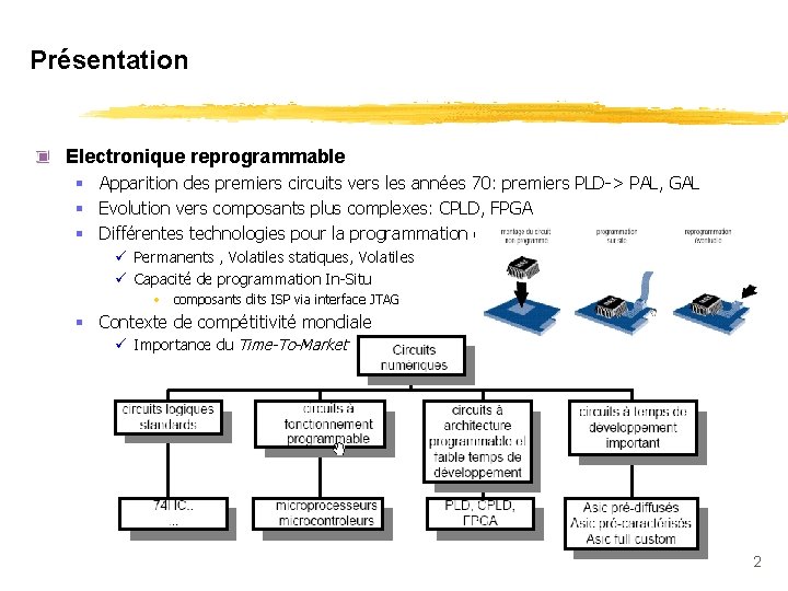
Présentation Electronique reprogrammable § Apparition des premiers circuits vers les années 70: premiers PLD-> PAL, GAL § Evolution vers composants plus complexes: CPLD, FPGA § Différentes technologies pour la programmation des connexions ü Permanents , Volatiles statiques, Volatiles ü Capacité de programmation In-Situ • composants dits ISP via interface JTAG § Contexte de compétitivité mondiale ü Importance du Time-To-Market 2
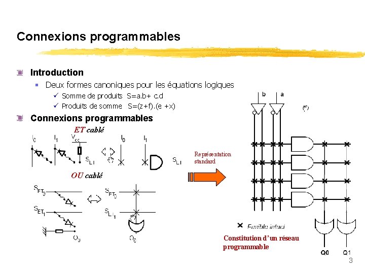
Connexions programmables Introduction § Deux formes canoniques pour les équations logiques ü Somme de produits S=a. b+ c. d ü Produits de somme S=(z+f). (e +x) Connexions programmables ET cablé Représentation standard OU cablé Constitution d’un réseau programmable 3
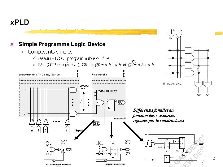
x. PLD Simple Programme Logic Device § Composants simples ü réseau ET/OU programmable ou fixe ü PAL (OTP en général), GAL reprogrammable Différentes familles en fonction des ressources rajoutés par le constructeurs 4
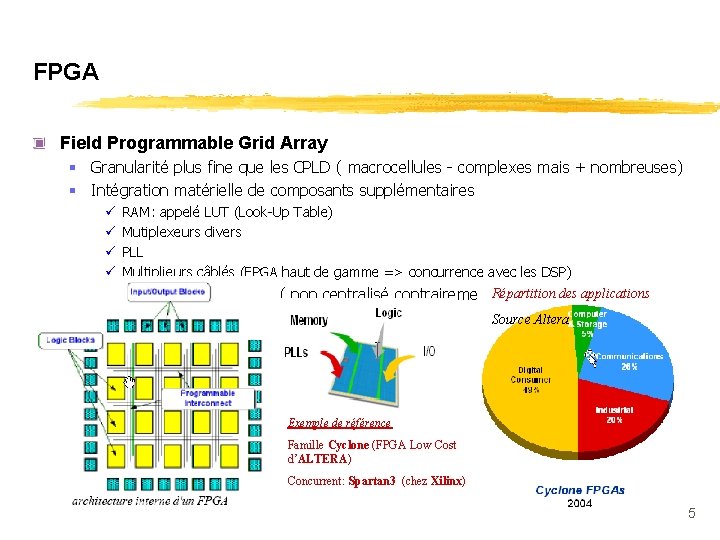
FPGA Field Programmable Grid Array § Granularité plus fine que les CPLD ( macrocellules - complexes mais + nombreuses) § Intégration matérielle de composants supplémentaires ü ü RAM: appelé LUT (Look-Up Table) Mutiplexeurs divers PLL Multiplieurs câblés (FPGA haut de gamme => concurrence avec les DSP) Répartition des applications § Réseau de routage réparti ( non centralisé contrairement aux CPLD) Source Altera Exemple de référence Famille Cyclone (FPGA Low Cost d’ALTERA) Concurrent: Spartan 3 (chez Xilinx) 5
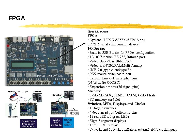
FPGA La carte DE 2 (utilisé en TP) Specifications FPGA • Cyclone II EP 2 C 35 F 672 C 6 FPGA and EPCS 16 serial configuration device I/O Devices • Built-in USB Blaster for FPGA configuration • 10/100 Ethernet, RS-232, Infrared port • Video Out (VGA 10 -bit DAC) • Video In (NTSC/PAL/Multi-format) • USB 2. 0 (type A and type B) • PS/2 mouse or keyboard port • Line-in, Line-out, microphone-in (24 -bit audio CODEC) • Expansion headers (76 signal pins) Memory • 8 -MB SDRAM, 512 -KB SRAM, 4 -MB Flash • SD memory card slot Switches, LEDs, Displays, and Clocks • 18 toggle switches • 4 debounced pushbutton switches • 18 red LEDs, 9 green LEDs • Eight 7 -segment displays • 16 x 2 LCD display • 27 -MHz and 50 -MHz oscillators, external SMA clock input 6
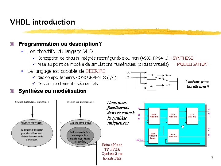
VHDL introduction Programmation ou description? § Les objectifs du langage VHDL ü Conception de circuits intégrés reconfigurable ou non (ASIC, FPGA…) : SYNTHESE ü Mise au point de modèle de simulations numériques (circuits virtuels) : MODELISATION § Le langage est capable de DECRIRE ü des comportements CONCURRENTS ( // ) ü Des comportements séquentiels Synthèse ou modélisation Les deux portes travaillent en // Nous nous focaliserons dans ce cours à la synthèse uniquement Notre cible en TP: FPGA Cyclone 2 sur la carte DE 2 7
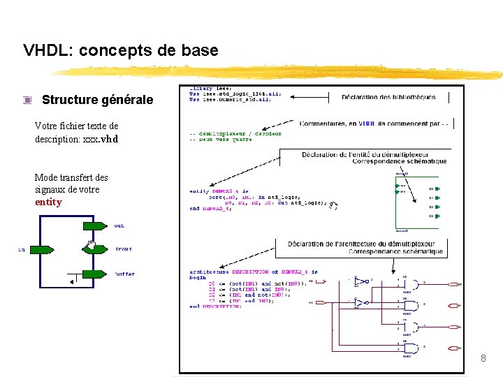
VHDL: concepts de base Structure générale Votre fichier texte de description: xxx. vhd Mode transfert des signaux de votre entity 8
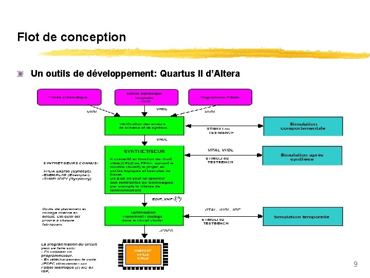
Flot de conception Un outils de développement: Quartus II d’Altera 9
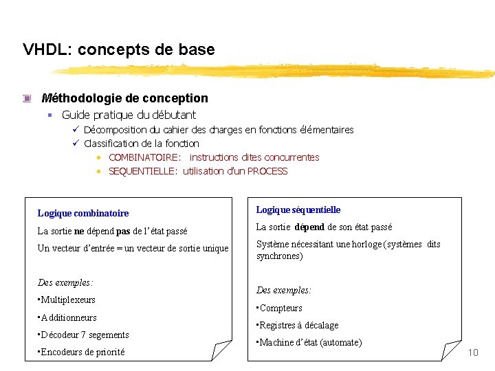
VHDL: concepts de base Méthodologie de conception § Guide pratique du débutant ü Décomposition du cahier des charges en fonctions élémentaires ü Classification de la fonction • COMBINATOIRE: instructions dites concurrentes • SEQUENTIELLE: utilisation d’un PROCESS Logique combinatoire Logique séquentielle La sortie ne dépend pas de l’état passé La sortie dépend de son état passé Un vecteur d’entrée = un vecteur de sortie unique Système nécessitant une horloge (systèmes dits synchrones) Des exemples: • Multiplexeurs • Additionneurs • Décodeur 7 segements • Encodeurs de priorité Des exemples: • Compteurs • Registres à décalage • Machine d’état (automate) 10
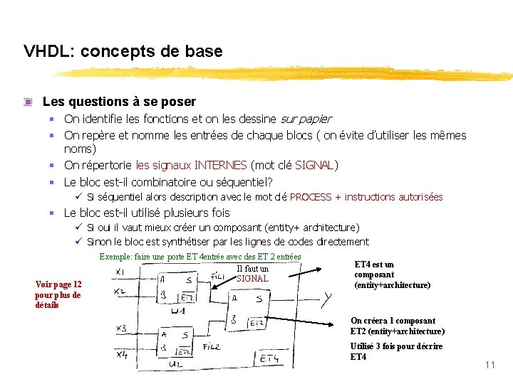
VHDL: concepts de base Les questions à se poser § On identifie les fonctions et on les dessine sur papier § On repère et nomme les entrées de chaque blocs ( on évite d’utiliser les mêmes noms) § On répertorie les signaux INTERNES (mot clé SIGNAL) § Le bloc est-il combinatoire ou séquentiel? ü Si séquentiel alors description avec le mot clé PROCESS + instructions autorisées § Le bloc est-il utilisé plusieurs fois ü Si oui il vaut mieux créer un composant (entity+ architecture) ü Sinon le bloc est synthétiser par les lignes de codes directement Voir page 12 pour plus de détails Exemple: faire une porte ET 4 entrée avec des ET 2 entrées Il faut un SIGNAL ET 4 est un composant (entity+architecture) On créera 1 composant ET 2 (entity+architecture) Utilisé 3 fois pour décrire ET 4 11
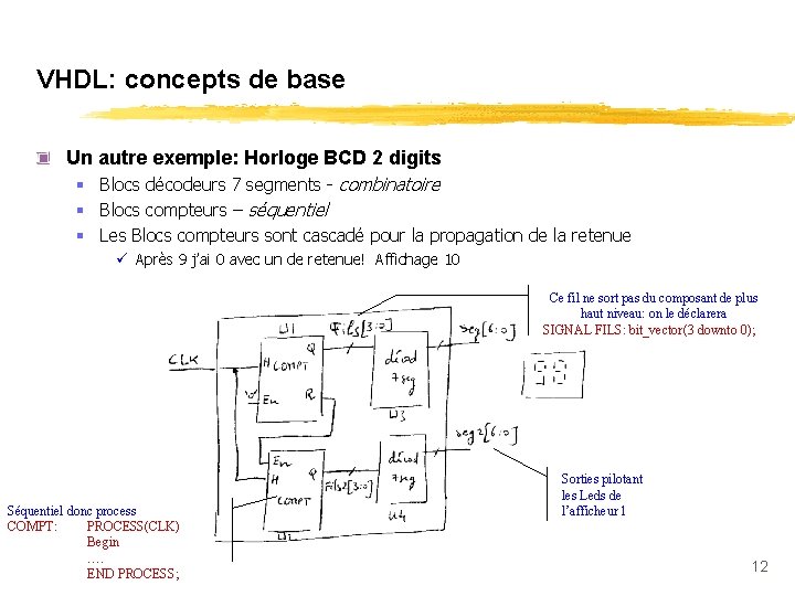
VHDL: concepts de base Un autre exemple: Horloge BCD 2 digits § Blocs décodeurs 7 segments - combinatoire § Blocs compteurs – séquentiel § Les Blocs compteurs sont cascadé pour la propagation de la retenue ü Après 9 j’ai 0 avec un de retenue! Affichage 10 Ce fil ne sort pas du composant de plus haut niveau: on le déclarera SIGNAL FILS: bit_vector(3 downto 0); Séquentiel donc process COMPT: PROCESS(CLK) Begin …. END PROCESS; Sorties pilotant les Leds de l’afficheur 1 12
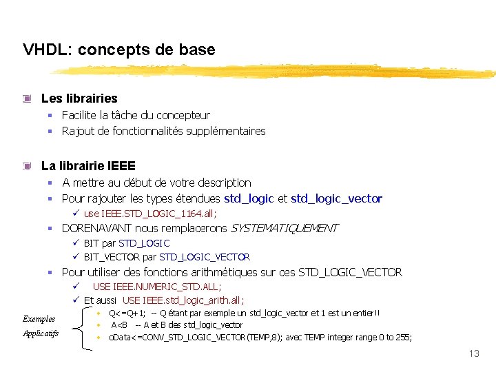
VHDL: concepts de base Les librairies § Facilite la tâche du concepteur § Rajout de fonctionnalités supplémentaires La librairie IEEE § A mettre au début de votre description § Pour rajouter les types étendues std_logic et std_logic_vector ü use IEEE. STD_LOGIC_1164. all; § DORENAVANT nous remplacerons SYSTEMATIQUEMENT ü BIT par STD_LOGIC ü BIT_VECTOR par STD_LOGIC_VECTOR § Pour utiliser des fonctions arithmétiques sur ces STD_LOGIC_VECTOR ü USE IEEE. NUMERIC_STD. ALL; ü Et aussi USE IEEE. std_logic_arith. all; Exemples Applicatifs • Q<=Q+1; -- Q étant par exemple un std_logic_vector et 1 est un entier!! • A<B -- A et B des std_logic_vector • o. Data<=CONV_STD_LOGIC_VECTOR(TEMP, 8); avec TEMP integer range 0 to 255; 13
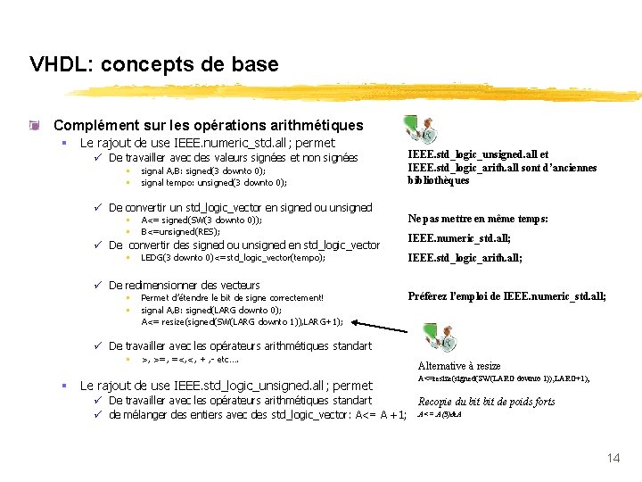
VHDL: concepts de base Complément sur les opérations arithmétiques § Le rajout de use IEEE. numeric_std. all; permet ü De travailler avec des valeurs signées et non signées • • signal A, B: signed(3 downto 0); signal tempo: unsigned(3 downto 0); ü De convertir un std_logic_vector en signed ou unsigned • • A<= signed(SW(3 downto 0)); B<=unsigned(RES); ü De convertir des signed ou unsigned en std_logic_vector • LEDG(3 downto 0)<=std_logic_vector(tempo); ü De redimensionner des vecteurs • • Permet d’étendre le bit de signe correctement! signal A, B: signed(LARG downto 0); A<= resize(signed(SW(LARG downto 1)), LARG+1); IEEE. std_logic_unsigned. all et IEEE. std_logic_arith. all sont d’anciennes bibliothèques Ne pas mettre en même temps: IEEE. numeric_std. all; IEEE. std_logic_arith. all; Préfèrez l’emploi de IEEE. numeric_std. all; ü De travailler avec les opérateurs arithmétiques standart • § >, >=, =<, <, + , - etc…. Le rajout de use IEEE. std_logic_unsigned. all; permet Alternative à resize A<=resize(signed(SW(LARG downto 1)), LARG+1); ü De travailler avec les opérateurs arithmétiques standart Recopie du bit de poids forts ü de mélanger des entiers avec des std_logic_vector: A<= A +1; A<= A(3)&A 14
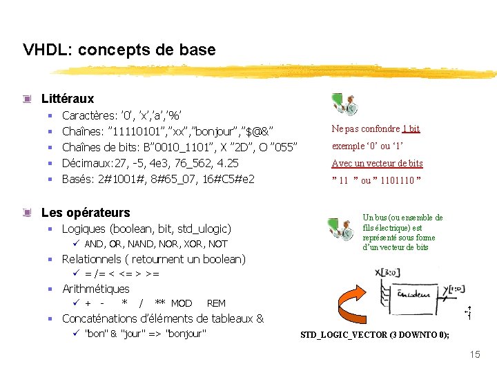
VHDL: concepts de base Littéraux § § § Caractères: ’ 0’, ’x’, ’a’, ’%’ Chaînes: ” 11110101”, ”xx”, ”bonjour”, ”$@&” Chaînes de bits: B” 0010_1101”, X ” 2 D”, O ” 055” Décimaux: 27, -5, 4 e 3, 76_562, 4. 25 Basés: 2#1001#, 8#65_07, 16#C 5#e 2 Les opérateurs § Logiques (boolean, bit, std_ulogic) ü AND, OR, NAND, NOR, XOR, NOT § Relationnels ( retournent un boolean) Ne pas confondre 1 bit exemple ‘ 0’ ou ‘ 1’ Avec un vecteur de bits ” 11 ” ou ” 1101110 ” Un bus (ou ensemble de fils électrique) est représenté sous forme d’un vecteur de bits ü = /= < <= > >= § Arithmétiques ü + - * / ** MOD REM § Concaténations d’éléments de tableaux & ü "bon" & "jour" => "bonjour" STD_LOGIC_VECTOR (3 DOWNTO 0); 15
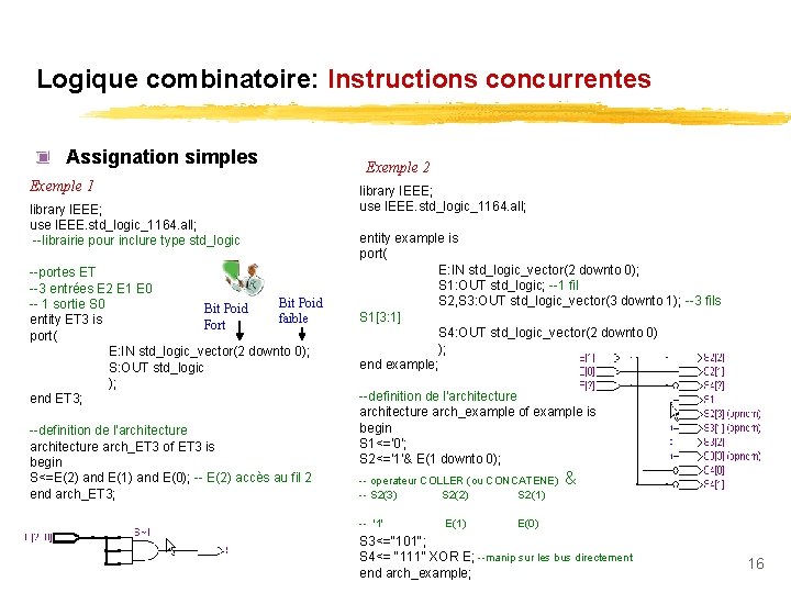
Logique combinatoire: Instructions concurrentes Assignation simples Exemple 1 library IEEE; use IEEE. std_logic_1164. all; --librairie pour inclure type std_logic --portes ET --3 entrées E 2 E 1 E 0 Bit Poid -- 1 sortie S 0 Bit Poid faible entity ET 3 is Fort port( E: IN std_logic_vector(2 downto 0); S: OUT std_logic ); end ET 3; --definition de l'architecture arch_ET 3 of ET 3 is begin S<=E(2) and E(1) and E(0); -- E(2) accès au fil 2 end arch_ET 3; Exemple 2 library IEEE; use IEEE. std_logic_1164. all; entity example is port( E: IN std_logic_vector(2 downto 0); S 1: OUT std_logic; --1 fil S 2, S 3: OUT std_logic_vector(3 downto 1); --3 fils S 1[3: 1] S 4: OUT std_logic_vector(2 downto 0) ); end example; --definition de l'architecture arch_example of example is begin S 1<='0'; S 2<='1'& E(1 downto 0); -- operateur COLLER (ou CONCATENE) -- S 2(3) S 2(2) S 2(1) -- '1' E(1) & E(0) S 3<="101"; S 4<= "111" XOR E; --manip sur les bus directement end arch_example; 16
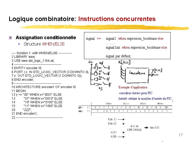
Logique combinatoire: Instructions concurrentes Assignation conditionnelle signal <= § Structure WHEN/ELSE ---- Solution 1: with WHEN/ELSE ------2 LIBRARY ieee; 3 USE ieee. std_logic_1164. all; 4 ----------------------5 ENTITY encoder IS 6 PORT ( x: IN STD_LOGIC_VECTOR (3 DOWNTO 0); 7 y: OUT STD_LOGIC_VECTOR (1 DOWNTO 0)); 8 END encoder; 9 ----------------------10 ARCHITECTURE encoder 1 OF encoder IS 11 BEGIN 12 y <= "00" WHEN x="0001" ELSE 13 "01" WHEN x="0010" ELSE 14 "10" WHEN x="0100" ELSE 15 "11" WHEN x="1000" ELSE 20 "ZZZ"; 21 END encoder 1; 22 ----------------------- signal 1 when expresion_boolénne else ……… signal 1 xx when expresion_boolénne else signal par défaut; Exemple d’application: encodeur clavier pour PIC Intérêt: réduire le nombre d’entrée du PIC 17
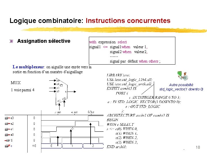
Logique combinatoire: Instructions concurrentes Assignation sélective with expression select signal 1 <= signal 1 when valeur 1, signal 2 when valeur 2, ----- signal par défaut when others ; Le multiplexeur: on aiguille une enrée vers la sortie en fonction d’un numéro d’aiguillage MUX 1 voie parmi 4 Autre possibilté: std_logic_vector(1 downto 0) 18
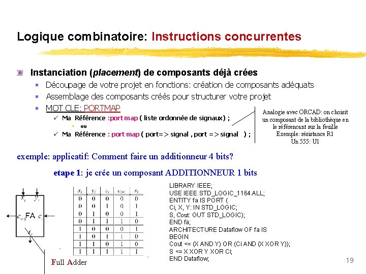
Logique combinatoire: Instructions concurrentes Instanciation (placement) de composants déjà crées § Découpage de votre projet en fonctions: création de composants adéquats § Assemblage des composants créés pour structurer votre projet § MOT CLE: PORTMAP Analogie avec ORCAD: on choisit ü Ma Référence : port map ( liste ordonnée de signaux) ; • ou ü Ma Référence : port map ( port=> signal , port => signal ) ; un composant de la bibliothèque en le référencant sur la feuille Exemple: résistance R 1 Un 555: U 1 exemple: applicatif: Comment faire un additionneur 4 bits? etape 1: je crée un composant ADDITIONNEUR 1 bits Full Adder LIBRARY IEEE; USE IEEE. STD_LOGIC_1164. ALL; ENTITY fa IS PORT ( Ci, X, Y: IN STD_LOGIC; S, Cout: OUT STD_LOGIC); END fa; ARCHITECTURE Dataflow OF fa IS BEGIN Cout <= (X AND Y) OR (Ci AND (X XOR Y)); S <= X XOR Y XOR Ci; END Dataflow; 19
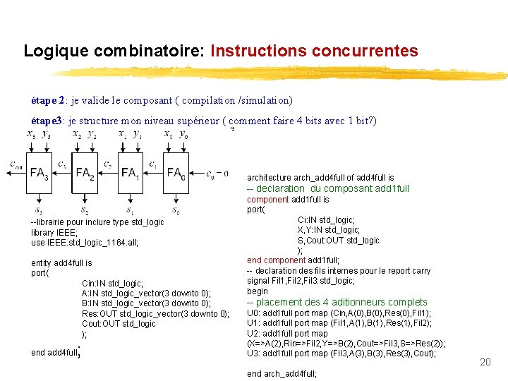
Logique combinatoire: Instructions concurrentes étape 2: je valide le composant ( compilation /simulation) étape 3: je structure mon niveau supérieur ( comment faire 4 bits avec 1 bit? ) architecture arch_add 4 full of add 4 full is -- declaration du composant add 1 full --librairie pour inclure type std_logic library IEEE; use IEEE. std_logic_1164. all; entity add 4 full is port( Cin: IN std_logic; A: IN std_logic_vector(3 downto 0); B: IN std_logic_vector(3 downto 0); Res: OUT std_logic_vector(3 downto 0); Cout: OUT std_logic ); ; end add 4 full component add 1 full is port( Ci: IN std_logic; X, Y: IN std_logic; S, Cout: OUT std_logic ); end component add 1 full; -- declaration des fils internes pour le report carry signal Fil 1, Fil 2, Fil 3: std_logic; begin -- placement des 4 aditionneurs complets U 0: add 1 full port map (Cin, A(0), B(0), Res(0), Fil 1); U 1: add 1 full port map (Fil 1, A(1), B(1), Res(1), Fil 2); U 2: add 1 full port map (X=>A(2), Rin=>Fil 2, Y=>B(2), Cout=>Fil 3, S=>Res(2)); U 3: add 1 full port map (Fil 3, A(3), B(3), Res(3), Cout); end arch_add 4 full; 20
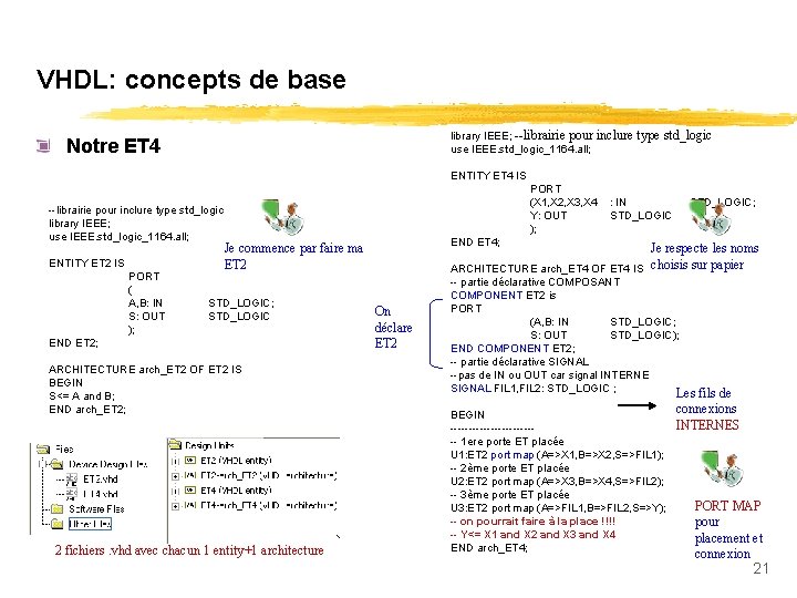
VHDL: concepts de base library IEEE; --librairie pour inclure type std_logic use IEEE. std_logic_1164. all; Notre ET 4 ENTITY ET 4 IS --librairie pour inclure type std_logic library IEEE; use IEEE. std_logic_1164. all; ENTITY ET 2 IS PORT ( A, B: IN S: OUT ); PORT (X 1, X 2, X 3, X 4 Y: OUT ); END ET 2; ARCHITECTURE arch_ET 2 OF ET 2 IS BEGIN S<= A and B; END arch_ET 2; 2 fichiers. vhd avec chacun 1 entity+1 architecture STD_LOGIC; END ET 4; Je commence par faire ma ET 2 STD_LOGIC; STD_LOGIC : IN STD_LOGIC Je respecte les noms ARCHITECTURE arch_ET 4 OF ET 4 IS choisis sur papier On déclare ET 2 -- partie déclarative COMPOSANT COMPONENT ET 2 is PORT (A, B: IN STD_LOGIC; S: OUT STD_LOGIC); END COMPONENT ET 2; -- partie déclarative SIGNAL --pas de IN ou OUT car signal INTERNE SIGNAL FIL 1, FIL 2: STD_LOGIC ; Les fils de BEGIN ------------ 1 ere porte ET placée U 1: ET 2 port map (A=>X 1, B=>X 2, S=>FIL 1); -- 2ème porte ET placée U 2: ET 2 port map (A=>X 3, B=>X 4, S=>FIL 2); -- 3ème porte ET placée U 3: ET 2 port map (A=>FIL 1, B=>FIL 2, S=>Y); -- on pourrait faire à la place !!!! -- Y<= X 1 and X 2 and X 3 and X 4 END arch_ET 4; connexions INTERNES PORT MAP pour placement et connexion 21
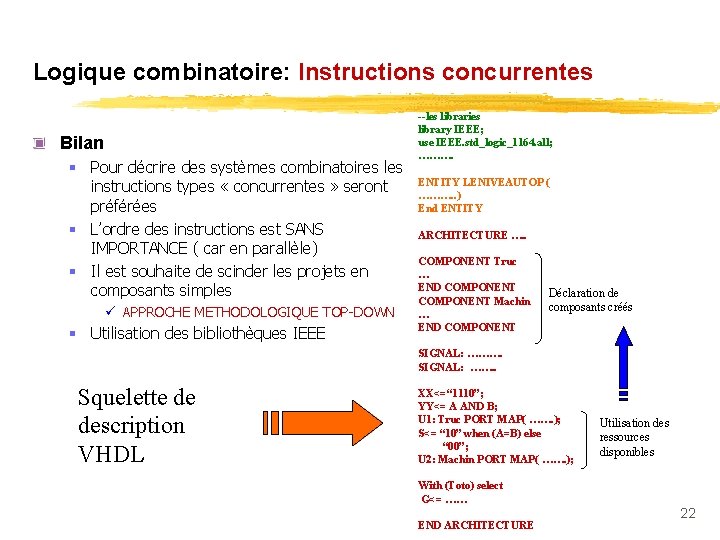
Logique combinatoire: Instructions concurrentes Bilan § Pour décrire des systèmes combinatoires les instructions types « concurrentes » seront préférées § L’ordre des instructions est SANS IMPORTANCE ( car en parallèle) § Il est souhaite de scinder les projets en composants simples ü APPROCHE METHODOLOGIQUE TOP-DOWN § Utilisation des bibliothèques IEEE --les libraries library IEEE; use IEEE. std_logic_1164. all; ………. ENTITY LENIVEAUTOP ( ………. . ) End ENTITY ARCHITECTURE …. . COMPONENT Truc … END COMPONENT Machin … END COMPONENT Déclaration de composants créés SIGNAL: ………. SIGNAL: ……. . Squelette de description VHDL XX<=“ 1110”; YY<= A AND B; U 1: Truc PORT MAP( ……. ); S<= “ 10” when (A=B) else “ 00”; U 2: Machin PORT MAP( ……. ); Utilisation des ressources disponibles With (Toto) select G<= …… END ARCHITECTURE 22
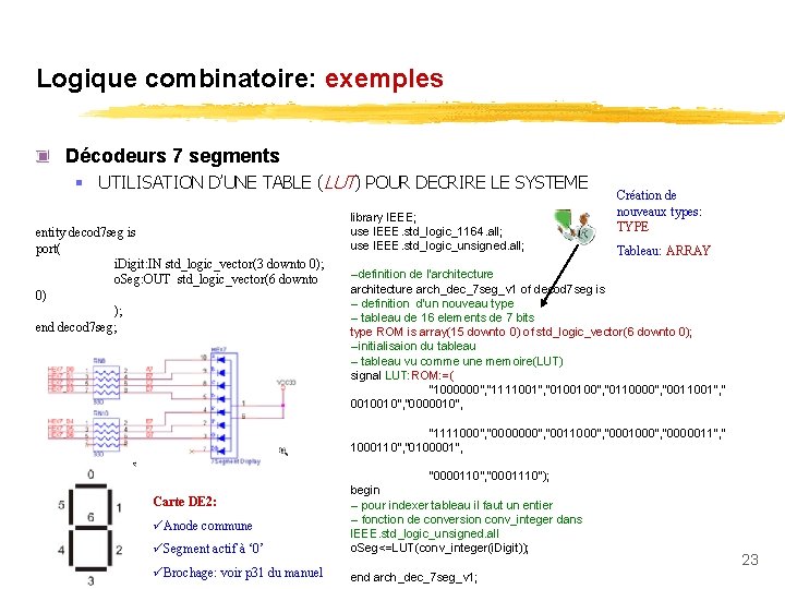
Logique combinatoire: exemples Décodeurs 7 segments § UTILISATION D’UNE TABLE (LUT) POUR DECRIRE LE SYSTEME entity decod 7 seg is port( i. Digit: IN std_logic_vector(3 downto 0); o. Seg: OUT std_logic_vector(6 downto 0) ); end decod 7 seg; library IEEE; use IEEE. std_logic_1164. all; use IEEE. std_logic_unsigned. all; Création de nouveaux types: TYPE Tableau: ARRAY --definition de l'architecture arch_dec_7 seg_v 1 of decod 7 seg is -- definition d'un nouveau type -- tableau de 16 elements de 7 bits type ROM is array(15 downto 0) of std_logic_vector(6 downto 0); --initialisaion du tableau -- tableau vu comme une memoire(LUT) signal LUT: ROM: =( "1000000", "1111001", "0100100", "0110000", "0011001", " 0010010", "0000010", "1111000", "0000000", "0011000", "0000011", " 1000110", "0100001", üSegment actif à ‘ 0’ "0000110", "0001110"); begin -- pour indexer tableau il faut un entier -- fonction de conversion conv_integer dans IEEE. std_logic_unsigned. all o. Seg<=LUT(conv_integer(i. Digit)); üBrochage: voir p 31 du manuel end arch_dec_7 seg_v 1; Carte DE 2: üAnode commune 23
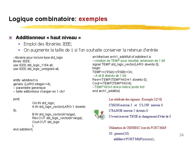
Logique combinatoire: exemples Additionneur « haut niveau » § Emploi des librairies IEEE; § On augmente la taille de 1 si l’on souhaite conserver la retenue d’entrée --librairie pour inclure type std_logic library IEEE; use IEEE. std_logic_1164. all; use IEEE. std_logic_unsigned. all; entity adddirect is generic (LARG: integer: =4); -- parametre generique -- taille aditionneur changer en 1 clic! port( architecture arch 1_add 4 full of adddirect is --creation de TEMP pour resultat: extension de 1 bit signal TEMP: std_logic_vector(LARG downto 0); begin TEMP<=('0'&A)+('0'&B)+Cin; --A et B etendu de 1 bit. Res<=TEMP(TEMP'HIGH-1 downto 0); Cout<=TEMP(TEMP'HIGH); --TEMP'HIGH renvoi indice poids fort end arch 1_add 4 full; Les attributs des signaux -Exemple S[5: 0] Cin: IN std_logic; A: IN std_logic_vector(LARG-1 downto 0); B: IN std_logic_vector(A'range); Res: OUT std_logic_vector(A'range); Cout: OUT std_logic ); end adddirect; S’HIGH renvoie 5 et S’LOW renvoie 0 S’RANGE renvoie 5 downto 0 S’event renvoie TRUE si changement d’état de S Utilisation de GENERIC lors du PORT MAP U 1: generic(10) adddirect PORT MAP(xxxxxx); 24
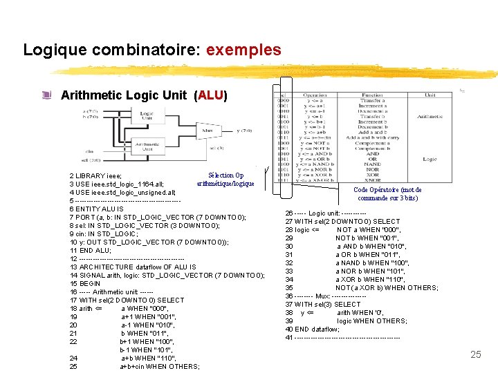
Logique combinatoire: exemples Arithmetic Logic Unit (ALU) Sélection Op 2 LIBRARY ieee; arithmétique/logique 3 USE ieee. std_logic_1164. all; 4 USE ieee. std_logic_unsigned. all; 5 -----------------------6 ENTITY ALU IS 7 PORT (a, b: IN STD_LOGIC_VECTOR (7 DOWNTO 0); 8 sel: IN STD_LOGIC_VECTOR (3 DOWNTO 0); 9 cin: IN STD_LOGIC; 10 y: OUT STD_LOGIC_VECTOR (7 DOWNTO 0)); 11 END ALU; 12 -----------------------13 ARCHITECTURE dataflow OF ALU IS 14 SIGNAL arith, logic: STD_LOGIC_VECTOR (7 DOWNTO 0); 15 BEGIN 16 ----- Arithmetic unit: -----17 WITH sel(2 DOWNTO 0) SELECT 18 arith <= a WHEN "000", 19 a+1 WHEN "001", 20 a-1 WHEN "010", 21 b WHEN "011", 22 b+1 WHEN "100", b-1 WHEN "101", 24 a+b WHEN "110", 25 a+b+cin WHEN OTHERS; Code Opératoire (mot de commande sur 3 bits) 26 ----- Logic unit: -----27 WITH sel(2 DOWNTO 0) SELECT 28 logic <= NOT a WHEN "000", 29 NOT b WHEN "001", 30 a AND b WHEN "010", 31 a OR b WHEN "011", 32 a NAND b WHEN "100", 33 a NOR b WHEN "101", 34 a XOR b WHEN "110", 35 NOT (a XOR b) WHEN OTHERS; 36 ---- Mux: -------37 WITH sel(3) SELECT 38 y <= arith WHEN '0', 39 logic WHEN OTHERS; 40 END dataflow; 41 ----------------------- 25
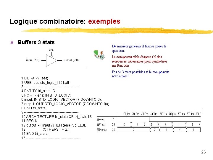
Logique combinatoire: exemples Buffers 3 états De manière générale il faut se poser la question: Le composant cible dispose t’il des ressources nécessaires pour synthétiser ma fonction 1 LIBRARY ieee; 2 USE ieee. std_logic_1164. all; 3 -----------------------4 ENTITY tri_state IS 5 PORT ( ena: IN STD_LOGIC; 6 input: IN STD_LOGIC_VECTOR (7 DOWNTO 0); 7 output: OUT STD_LOGIC_VECTOR (7 DOWNTO 0)); 8 END tri_state; 9 -----------------------10 ARCHITECTURE tri_state OF tri_state IS 11 BEGIN 12 output <= input WHEN (ena='0') ELSE 13 (OTHERS => 'Z'); 14 END tri_state; 15 ----------------------- Pas de 3 états possibles si le composants n’en a pas!! 26
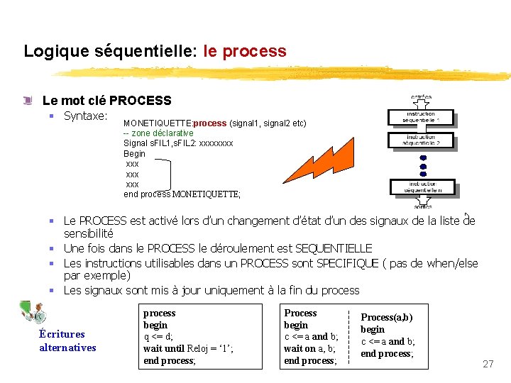
Logique séquentielle: le process Le mot clé PROCESS § Syntaxe: MONETIQUETTE: process (signal 1, signal 2 etc) -- zone déclarative Signal s. FIL 1, s. FIL 2: xxxx Begin xxx xxx end process MONETIQUETTE; § Le PROCESS est activé lors d’un changement d’état d’un des signaux de la liste de sensibilité § Une fois dans le PROCESS le déroulement est SEQUENTIELLE § Les instructions utilisables dans un PROCESS sont SPECIFIQUE ( pas de when/else par exemple) § Les signaux sont mis à jour uniquement à la fin du process Écritures alternatives process begin q <= d; wait until Reloj = ‘ 1’; end process; Process begin c <= a and b; wait on a, b; end process; Process(a, b) begin c <= a and b; end process; 27
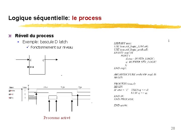
Logique séquentielle: le process Réveil du process § Exemple: bascule D latch ü Fonctionnement sur niveau Processus activé 28
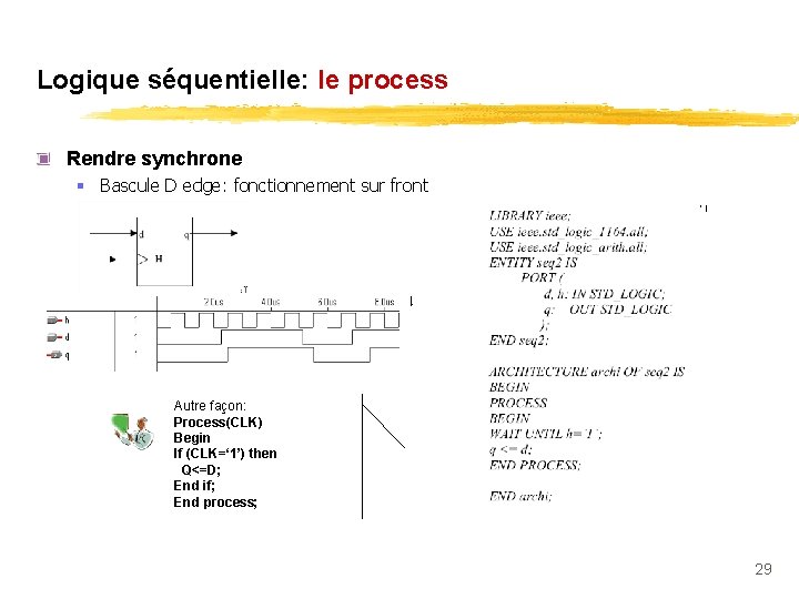
Logique séquentielle: le process Rendre synchrone § Bascule D edge: fonctionnement sur front Autre façon: Process(CLK) Begin If (CLK=‘ 1’) then Q<=D; End if; End process; 29
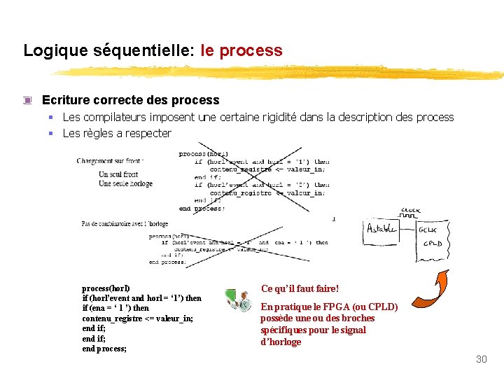
Logique séquentielle: le process Ecriture correcte des process § Les compilateurs imposent une certaine rigidité dans la description des process § Les règles a respecter process(horl) if (horl’event and horl = ‘ 1’) then if (ena = ‘ 1 ’) then contenu_registre <= valeur_in; end if; end process; Ce qu’il faut faire! En pratique le FPGA (ou CPLD) possède une ou des broches spécifiques pour le signal d’horloge 30
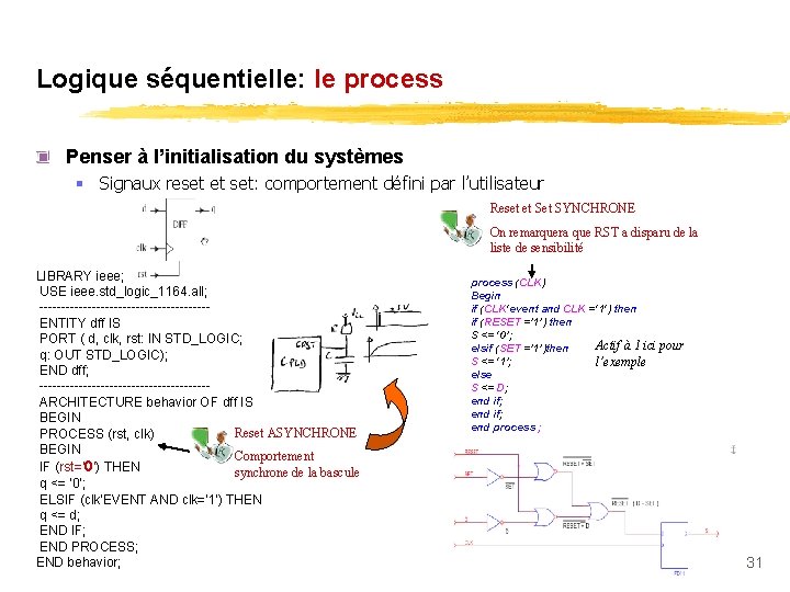
Logique séquentielle: le process Penser à l’initialisation du systèmes § Signaux reset et set: comportement défini par l’utilisateur Reset et SYNCHRONE On remarquera que RST a disparu de la liste de sensibilité LIBRARY ieee; USE ieee. std_logic_1164. all; -------------------ENTITY dff IS PORT ( d, clk, rst: IN STD_LOGIC; q: OUT STD_LOGIC); END dff; -------------------ARCHITECTURE behavior OF dff IS BEGIN Reset ASYNCHRONE PROCESS (rst, clk) BEGIN Comportement IF (rst=‘ 0') THEN synchrone de la bascule q <= '0'; ELSIF (clk'EVENT AND clk='1') THEN q <= d; END IF; END PROCESS; END behavior; process (CLK) Begin if (CLK'event and CLK ='1') then if (RESET =’ 1’) then S <= ‘ 0’; Actif à 1 ici elsif (SET =’ 1’)then S <= ‘ 1’; l’exemple else S <= D; end if; end process ; pour 31
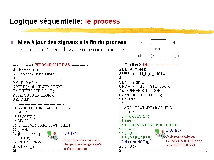
Logique séquentielle: le process Mise à jour des signaux à la fin du process § Exemple 1: bascule avec sortie complémentée ---- Solution 1: NE MARCHE PAS-------2 LIBRARY ieee; 3 USE ieee. std_logic_1164. all; 4 -------------------5 ENTITY dff IS 6 PORT ( d, clk: IN STD_LOGIC; 7 q: BUFFER STD_LOGIC; 8 qbar: OUT STD_LOGIC); 9 END dff; 10 -------------------11 ARCHITECTURE not_ok OF dff IS 12 BEGIN 13 PROCESS (clk) 14 BEGIN 15 IF (clk'EVENT AND clk='1') THEN 16 q <= d; LIGNE 17 17 qbar <= NOT q; 18 END IF; Je me fais avoir car si d a 19 END PROCESS; changé q ne changera qu’à 20 END not_ok; la fin du process 21 -------------------- Solution 2: OK ---------2 LIBRARY ieee; 3 USE ieee. std_logic_1164. all; 4 -------------------5 ENTITY dff IS 6 PORT ( d, clk: IN STD_LOGIC; 7 q: BUFFER STD_LOGIC; 8 qbar: OUT STD_LOGIC); 9 END dff; 10 -------------------11 ARCHITECTURE ok OF dff IS 12 BEGIN 13 PROCESS (clk) 14 BEGIN 15 IF (clk'EVENT AND clk='1') THEN 16 q <= d; LIGNE 19 17 END IF; Je décris un relation 18 END PROCESS; COMBINATOIRE => je 19 qbar <= NOT q; sors du PROCESS!!! 20 END ok; 21 -------------------- 32
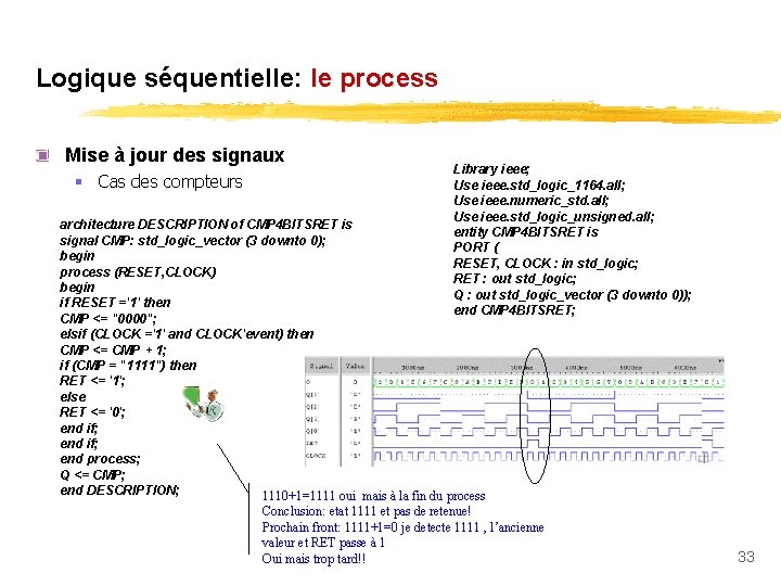
Logique séquentielle: le process Mise à jour des signaux § Cas des compteurs Library ieee; Use ieee. std_logic_1164. all; Use ieee. numeric_std. all; Use ieee. std_logic_unsigned. all; entity CMP 4 BITSRET is PORT ( RESET, CLOCK : in std_logic; RET : out std_logic; Q : out std_logic_vector (3 downto 0)); end CMP 4 BITSRET; architecture DESCRIPTION of CMP 4 BITSRET is signal CMP: std_logic_vector (3 downto 0); begin process (RESET, CLOCK) begin if RESET ='1' then CMP <= "0000"; elsif (CLOCK ='1' and CLOCK'event) then CMP <= CMP + 1; if (CMP = "1111") then RET <= '1'; else RET <= '0'; end if; end process; Q <= CMP; end DESCRIPTION; 1110+1=1111 oui mais à la fin du process Conclusion: etat 1111 et pas de retenue! Prochain front: 1111+1=0 je detecte 1111 , l’ancienne valeur et RET passe à 1 Oui mais trop tard!! 33
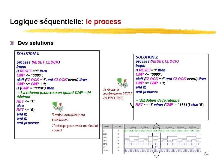
Logique séquentielle: le process Des solutions SOLUTION 1: process (RESET, CLOCK) begin if RESET ='1' then CMP <= "0000"; elsif (CLOCK ='1' and CLOCK'event) then CMP <= CMP + 1; if (CMP = "1110") then –- La retenue passera à un quand CMP = 14 décimal RET <= '1'; else RET <= '0'; end if; Version complètement end if; synchrone: end process; J’anticipe pour avoir un résultat correct Je décris le combinatoire HORS du PROCESS SOLUTION 2: process (RESET, CLOCK) begin if RESET='1' then CMP <= "0000"; elsif (CLOCK ='1' and CLOCK'event) then CMP <= CMP + 1; end if; end process; -- Validation de la retenue RET <= '1' when (CMP = "1111") else '0'; 34
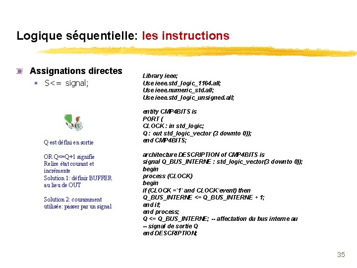
Logique séquentielle: les instructions Assignations directes § S<= signal; Q est défini en sortie OR Q<=Q+1 signifie Relire état courant et incrémente Solution 1: définir BUFFER au lieu de OUT Solution 2: couramment utilisée: passer par un signal Library ieee; Use ieee. std_logic_1164. all; Use ieee. numeric_std. all; Use ieee. std_logic_unsigned. all; entity CMP 4 BITS is PORT ( CLOCK : in std_logic; Q : out std_logic_vector (3 downto 0)); end CMP 4 BITS; architecture DESCRIPTION of CMP 4 BITS is signal Q_BUS_INTERNE : std_logic_vector(3 downto 0)); begin process (CLOCK) begin if (CLOCK ='1' and CLOCK'event) then Q_BUS_INTERNE <= Q_BUS_INTERNE + 1; end if; end process; Q <= Q_BUS_INTERNE; -- affectation du bus interne au -- signal de sortie Q end DESCRIPTION; 35
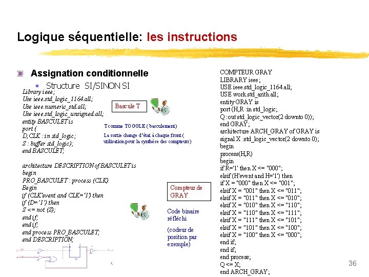
Logique séquentielle: les instructions Assignation conditionnelle § Structure SI/SINON SI Library ieee; Use ieee. std_logic_1164. all; Bascule T Use ieee. numeric_std. all; Use ieee. std_logic_unsigned. all; entity BASCULET is T comme TOGGLE ( basculement) port ( La sortie change d’état à chaque front ( D, CLK : in std_logic; utilisation pour la synthèse des compteurs) S : buffer std_logic); end BASCULET; architecture DESCRIPTION of BASCULET is begin PRO_BASCULET : process (CLK) Begin if (CLK'event and CLK='1') then if (D=’ 1’) then S <= not (S); end if; end process PRO_BASCULET; end DESCRIPTION; Compteur de GRAY Code binaire réfléchi (codeur de position par exemple) COMPTEUR GRAY LIBRARY ieee; USE ieee. std_logic_1164. all; USE work. std_arith. all; entity GRAY is port (H, R : in std_logic; Q : out std_logic_vector(2 downto 0)); end GRAY; architecture ARCH_GRAY of GRAY is signal X : std_logic_vector(2 downto 0); begin process(H, R) begin if R='1' then X <= "000"; elsif (H'event and H='1') then if X = "000" then X <= "001"; elsif X = "001" then X <= "011"; elsif X = "011" then X <= "010"; elsif X = "010" then X <= "110"; elsif X = "110" then X <= "111"; elsif X = "111" then X <= "101"; elsif X = "101" then X <= "100"; elsif X = "100" then X <= "000"; end if; end process; Q <= X; end ARCH_GRAY; 36
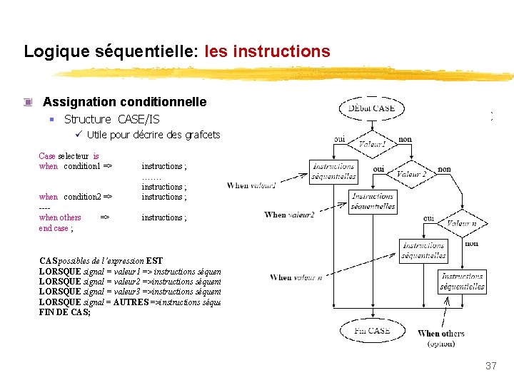
Logique séquentielle: les instructions Assignation conditionnelle § Structure CASE/IS ü Utile pour décrire des grafcets, machine d’états Case selecteur is when condition 1 => when condition 2 => ---when others => end case ; instructions ; ……. instructions ; CAS possibles de l’expression EST LORSQUE signal = valeur 1 => instructions séquentielles; LORSQUE signal = valeur 2 =>instructions séquentielles; LORSQUE signal = valeur 3 =>instructions séquentielles; LORSQUE signal = AUTRES =>instructions séquentielles; FIN DE CAS; 37
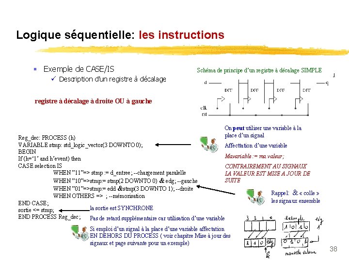
Logique séquentielle: les instructions § Exemple de CASE/IS Schéma de principe d’un registre à décalage SIMPLE ü Description d’un registre à décalage à droite OU à gauche On peut utiliser une variable à la place d’un signal Reg_dec: PROCESS (h) VARIABLE stmp: std_logic_vector(3 DOWNTO 0); Affecttation d’une variable BEGIN Mavariable: = ma valeur; If (h=‘ 1’ and h’event) then CASE selection IS CONTRAIREMENT AU SIGNAUX WHEN ” 11”=> stmp : = d_entree; --chargement paralelle LA VALEUR EST MISE A JOUR DE SUITE WHEN ” 10”=>stmp: = stmp(2 DOWNTO 0) & edg; --gauche WHEN ” 01”=>stmp: = edd &stmp(3 DOWNTO 1); --droite Rappel: & « colle » WHEN OTHERS => ; --mémorisation les signaux ensemble END CASE; la sortie est SYNCHRONE sortie <= stmp; END PROCESS Reg_dec; Pas de retard supplémentaire car utilisation d’une variable Si emploi d’un signal à la place d’une variable affectation EN DEHORS DU PROCESS ( voir chapitre Mise à jour des signaux et page suivante pour un exemple) 38
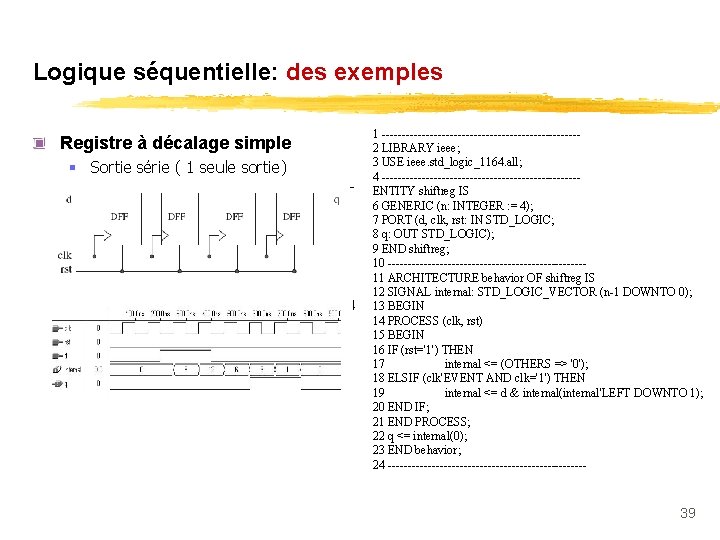
Logique séquentielle: des exemples Registre à décalage simple § Sortie série ( 1 seule sortie) 1 -------------------------2 LIBRARY ieee; 3 USE ieee. std_logic_1164. all; 4 -------------------------ENTITY shiftreg IS 6 GENERIC (n: INTEGER : = 4); 7 PORT (d, clk, rst: IN STD_LOGIC; 8 q: OUT STD_LOGIC); 9 END shiftreg; 10 -------------------------11 ARCHITECTURE behavior OF shiftreg IS 12 SIGNAL internal: STD_LOGIC_VECTOR (n-1 DOWNTO 0); 13 BEGIN 14 PROCESS (clk, rst) 15 BEGIN 16 IF (rst='1') THEN 17 internal <= (OTHERS => '0'); 18 ELSIF (clk'EVENT AND clk='1') THEN 19 internal <= d & internal(internal'LEFT DOWNTO 1); 20 END IF; 21 END PROCESS; 22 q <= internal(0); 23 END behavior; 24 ------------------------- 39
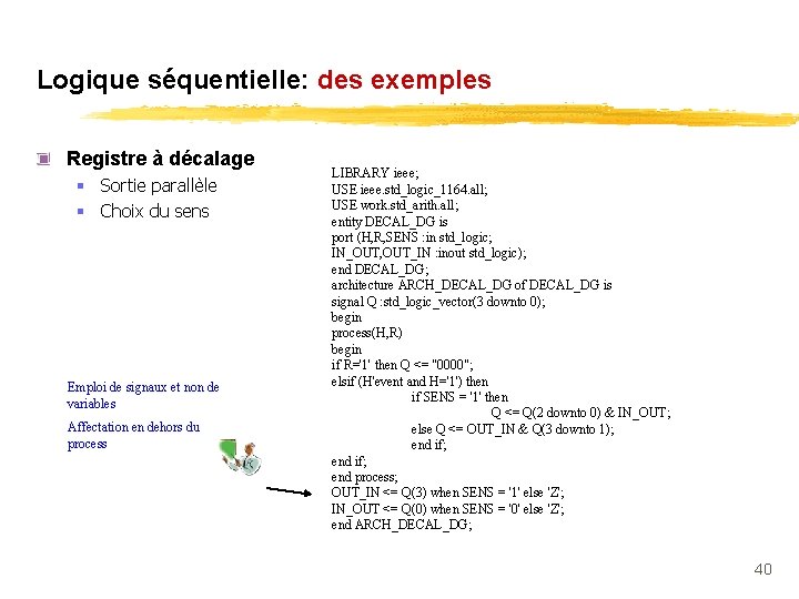
Logique séquentielle: des exemples Registre à décalage § Sortie parallèle § Choix du sens Emploi de signaux et non de variables Affectation en dehors du process LIBRARY ieee; USE ieee. std_logic_1164. all; USE work. std_arith. all; entity DECAL_DG is port (H, R, SENS : in std_logic; IN_OUT, OUT_IN : inout std_logic); end DECAL_DG; architecture ARCH_DECAL_DG of DECAL_DG is signal Q : std_logic_vector(3 downto 0); begin process(H, R) begin if R='1' then Q <= "0000"; elsif (H'event and H='1') then if SENS = '1' then Q <= Q(2 downto 0) & IN_OUT; else Q <= OUT_IN & Q(3 downto 1); end if; end process; OUT_IN <= Q(3) when SENS = '1' else 'Z'; IN_OUT <= Q(0) when SENS = '0' else 'Z'; end ARCH_DECAL_DG; 40
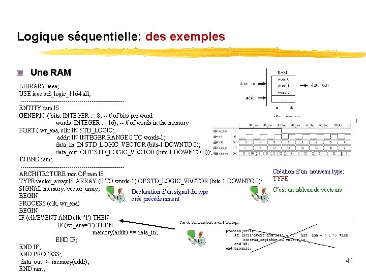
Logique séquentielle: des exemples Une RAM LIBRARY ieee; USE ieee. std_logic_1164. all; -------------------------ENTITY ram IS GENERIC ( bits: INTEGER : = 8; -- # of bits per words: INTEGER : = 16); -- # of words in the memory PORT ( wr_ena, clk: IN STD_LOGIC; addr: IN INTEGER RANGE 0 TO words-1; data_in: IN STD_LOGIC_VECTOR (bits-1 DOWNTO 0); data_out: OUT STD_LOGIC_VECTOR (bits-1 DOWNTO 0)); 12 END ram; -------------------------ARCHITECTURE ram OF ram IS TYPE vector_array IS ARRAY (0 TO words-1) OF STD_LOGIC_VECTOR (bits-1 DOWNTO 0); SIGNAL memory: vector_array; Déclaration d’un signal du type BEGIN créé précédemment PROCESS (clk, wr_ena) BEGIN IF (clk'EVENT AND clk='1') THEN IF (wr_ena='1') THEN memory(addr) <= data_in; END IF; END PROCESS; data_out <= memory(addr); END ram; Création d’un nouveau type: TYPE C’est un tableau de vecteurs 41
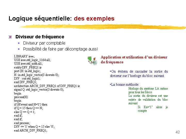
Logique séquentielle: des exemples Diviseur de fréquence § Diviseur par comptable § Possibilité de faire par décomptage aussi LIBRARY ieee; USE ieee. std_logic_1164. all; USE ieee. std_arith. all; entity DIV_FREQ 1 is port (H : in std_logic; N : in std_logic_vector(3 downto 0); DIV : out std_logic); end DIV_FREQ 1; architecture ARCH_DIV_FREQ 1 of DIV_FREQ 1 is signal Q : std_logic_vector(3 downto 0); begin process(H) begin if (H'event and H='1') then if Q = 15 then Q <= N; else Q <= Q + 1; end if; end process; DIV <= '1' when Q = 15 else '0'; end ARCH_DIV_FREQ 1; Application et utilisation d’un diviseur de fréquence • On évitera de cascader la sortie du diviseur sur l’horloge du bloc suivant • La bonne méthode: Horloge du système LA même pour tous les blocs La sortie du diviseur est une entrée de validation du bloc suivant Si En=‘ 1’ alors je compte 42
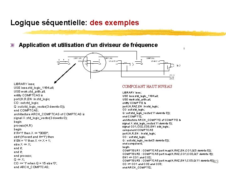
Logique séquentielle: des exemples Application et utilisation d’un diviseur de fréquence LIBRARY ieee; USE ieee. std_logic_1164. all; USE work. std_arith. all; entity COMPTCAS is port (H, R, EN : in std_logic; CO : out std_logic; Q : out std_logic_vector(3 downto 0)); end COMPTCAS; architecture ARCH_COMPTCAS of COMPTCAS is signal X : std_logic_vector(3 downto 0); begin process(H, R) begin if R='1' then X <= "0000"; elsif (H'event and H='1') then if EN = '1' then X <= X + 1; else X <= X; end if; end process; Q <= X; CO <= '1' when Q = 15 else '0'; end ARCH_COMPTCAS; COMPOSANT HAUT NIVEAU LIBRARY ieee; USE ieee. std_logic_1164. all; USE work. std_arith. all; entity COMPT 12 is port (H, RAZ, EN : in std_logic; CO : out std_logic; Q : out std_logic_vector(11 downto 0)); end COMPT 12; architecture ARCH_COMPT 12 of COMPT 12 is signal X : std_logic_vector(11 downto 0); signal CO 1, CO 2, CO 3, EN 1 : std_logic; component COMPTCAS port (H, R, EN : in std_logic; CO : out std_logic; Q : out std_logic_vector(3 downto 0)); end component; begin COMPTEUR 1 : COMPTCAS port map(H, RAZ, EN, CO 1, Q(3 downto 0)); COMPTEUR 2 : COMPTCAS port map(H, RAZ, CO 1, CO 2, Q(7 downto 4)); EN 1 <= CO 1 and CO 2; COMPTEUR 3 : COMPTCAS port map(H, RAZ, EN 1, CO 3, Q(11 downto 8)); 43 CO <= CO 1 and CO 2 and CO 3; end ARCH_COMPT 12;
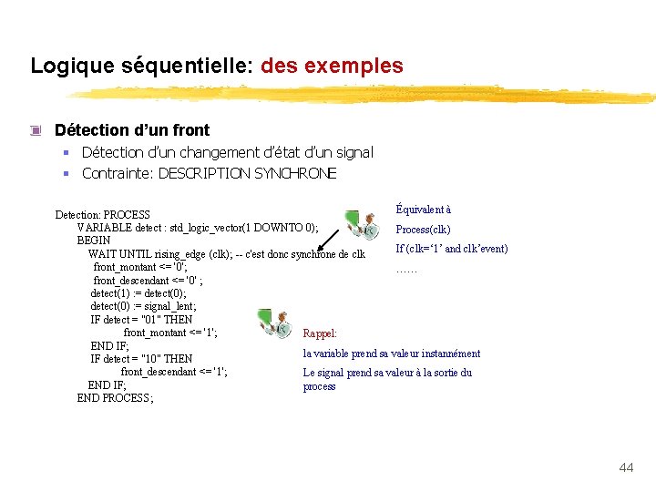
Logique séquentielle: des exemples Détection d’un front § Détection d’un changement d’état d’un signal § Contrainte: DESCRIPTION SYNCHRONE Équivalent à Detection: PROCESS VARIABLE detect : std_logic_vector(1 DOWNTO 0); Process(clk) BEGIN If (clk=‘ 1’ and clk’event) WAIT UNTIL rising_edge (clk); -- c'est donc synchrone de clk front_montant <= '0'; …… front_descendant <= '0' ; detect(1) : = detect(0); detect(0) : = signal_lent; IF detect = "01" THEN front_montant <= '1'; Rappel: END IF; la variable prend sa valeur instannément IF detect = "10" THEN front_descendant <= '1'; Le signal prend sa valeur à la sortie du END IF; process END PROCESS; 44
Bibliographie § Certaines illustrations et exemples proviennent de cours ou d’ouvrages présents cidessous ü ü Introduction à la Synthèse logique Philippe LECARDONNEL & Philippe LETENNEUR Le langage de description VHDL T. BLOTIN VHDl J. maillefert Circuit Design with VHDL Volnei A. Pedroni § Un lien bien utile pour l’étudiant GEII ü http: //perso. orange. fr/xcotton/electron/coursetdocs. htm 45
- Slides: 45