VHDL Rabee Shatnawi Rami Haddad What is this

VHDL Rabee Shatnawi & Rami Haddad

What is this presentation about? ! This presentation will introduce the key concepts in VHDL and the important syntax required for most VHDL designs,

Why to use VHDL? In most cases, the decision to use VHDL over other languages such as Verilog or System. C, will have less to do with designer choice, and more to do with software availability and company decisions…. Or the professor's choice ; -)

• Verilog has come from a ‘bottom-up’ tradition and has been heavily used by the IC industry for cell-based design, • whereas the VHDL language has been developed much more from a ‘topdown’ perspective. Of course, these are generalizations and largely out of date in a modern context
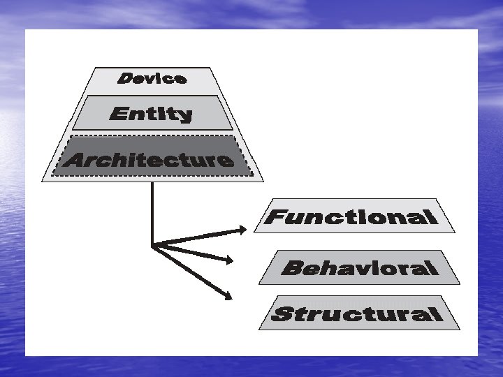

Entity: model interface • The entity defines how a design element described in VHDL connects to other VHDL models … • and also defines the name of the model. • It allows the definition of any parameters that are to be passed into the model using hierarchy.

Entity definition entity test is …. end entity test; • or: entity test is … end test;

Ports • How to connect Entities together? -The method of connecting entities together is using PORTS. - PORTS are defined in the entity using the following method: port (. . . list of port declarations. . . );

• The port declaration defines the type of The port declaration defines the connection and direction where connection and appropriate. port ( in 1, in 2 : in bit; out 1 : out bit );

Entity Port Modes • in: – signal values are read-only • out: – signal values are write-only • buffer: – comparable to out – signal values may be read, as well • inout: – bidirectional port

Generics If the model has a parameter, then it is defined using generics. generic ( gain : integer : = 4; time_delay : time = 10 ns );

Constants • It is also possible to include model specific constants in the entity using the standard declaration of constants method constant : rpullup : real : = 1000. 0;

a complete examples, meet our first Entity……. test entity test is port ( in 1, in 2 : in bit; out 1 : out bit ); generic ( gain : integer : = 4; time_delay : time : = 10 ns ); constant : rpullup : real : = 1000. 0; end entity test;

Architecture: model behavior • Implementation of the design • Always connected with a specific entity – one entity can have several architectures – entity ports are available as signals within the architecture • Contains concurrent statements

Basic definition of an architecture • While the entity describes the interface and parameter aspects of the model ………. • the architecture defines the behavior.

• There are several types of VHDL any local signals or architecture and …. variables • VHDL allows different architectures to be can be declared defined for the same entity. here architecture behaviour of test is . . architecture declarations begin . . . architecture contents end behaviour;

Signals • Signals are the primary objects describing the hardware system and are equivalent to “wires”. • They represent communication channels among concurrent statements of system application. • Signals can be declared in: – Package declaration – Architecture – Block: – Subprograms:

Hierarchical design • Functions • Packages • Components • Procedures

Functions • A simple way of encapsulating behavior in a model that can be reused in multiple architectures. • Can be defined locally to an architecture or more commonly in a package more commonly in a

• The simple form of a function is to define a header with the input and output variables as shown below: function name (input declarations) return output_type is. . . variable declarations begin. . . function body end
 return integer is begin return a * b;")
function mult (a, b : integer) return integer is begin return a * b; end;

Package : The header: is the place where the types Function containers and functions are declared package name is. . . package header contents end package; package body name is. . . package body contents package body: end package body; where the declarations themselves take place

Component
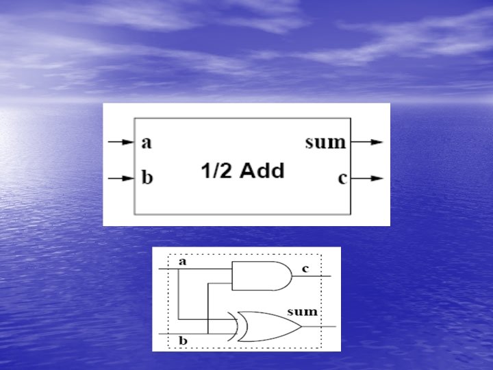

library ieee; use ieee. std_logic_1164. all; -- here is the entity halfadd is port (a, b : in std_logic; sum, c : out std_logic); end halfadd; architecture comp of halfadd is begin -- a concurrent statement implementing the and gate c <= a and b; -- a concurrent statement implementing the xor gate sum <= a xor b; end comp;

library ieee; use ieee. std_logic_1164. all; entity fulladd is port (ina, inb, inc : in std_logic; sumout, outc : out std_logic); end fulladd; architecture top of fulladd is component halfadd port (a, b : in std_logic; sum, c : out std_logic); end component; signal s 1, s 2, s 3 : std_logic; begin -- a structural instantiation of two half adders h 1: halfadd port map( a => ina, b => inb, sum => s 1, c => s 3); h 2: halfadd port map( a => s 1, b => inc, sum => sumout, c => s 2); outc <= s 2 or s 3; end top;

VHDL • Case insensitive • Comments: '--' until end of line Statements are terminated by '; ' (may span multiple lines) • List delimiter: ', ' • Signal assignment: '<=‘ • User defined names: – letters, numbers, underscores – start with a letter
 Identifier Letters, numerals, underscores • Case insensitive • No")
VHDL …. Identifier • (Normal) Identifier Letters, numerals, underscores • Case insensitive • No two consecutive underscores • Must begin with a letter • Not a VHDL keyword my. Signal_23 -- normal identifier rdy, RDY, Rdy -- identical identifiers vector_&_vector -- X : special character last of Zout -- X : white spaces idle__state -- X : consecutive underscores 24 th_signal -- X : begins with a numeral open, register -- X : VHDL keywords

VHDL Structural Elements • Entity : Interface Architecture : • Implementation, behavior, function • Configuration : Model chaining, structure, hierarchy • Process : Concurrency, event controlled • Package : Modular design, standard solution, • data types, constants • Library : Compilation, object code

Hierarchical Model Layout • VHDL allows for a hierarchical model layout, which means that a module can be assembled out of several submodules. The connections between these submodules are defined within the architecture of a top module. As you can see, a fulladder can be built with the help of two halfadders (module 1, module 2) and an OR gate (module 3).

Component : example ENTITY half_adder IS begin PORT ( A, B : IN STD_LOGIC; sum, carry : OUT STD_LOGIC ); END half_adder; MODULE 1: HALFADDER ARCHITECTURE structural OF half_adder IS port map( A, B, W_SUM, W_CARRY 1 ); entity FULLADDER is COMPONENT xor 2 port (A, B, CARRY_IN: in bit; PORT ( a, b : IN STD_LOGIC; MODULE 2: HALFADDER SUM, CARRY: out bit); c : OUT STD_LOGIC ); port map ( W_SUM, CARRY_IN, end FULLADDER; END COMPONENT; SUM, W_CARRY 2 ); architecture STRUCT of FULLADDER is COMPONENT and 2 begin signal W_SUM, W_CARRY 1, W_CARRY 2 : bit; PORT ( a, b : IN STD_LOGIC; ENTITY and 2 IS component HALFADDER MODULE 3: ORGATE c : OUT STD_LOGIC ); port (A, B : in bit; PORT ( a, b : IN STD_LOGIC; MODULE 1: HALFADDER port map ( W_CARRY 2, W_CARRY 1, CARRY ); SUM, CARRY : out bit); END COMPONENT; output : OUT STD_LOGIC ); port map ( A => A, end component; BEGIN END and 2; end STRUCT; SUM => W_SUM, component ORGATE ex 1 : xor 2 PORT MAP ( a => a, b => b, c => sum ); ARCHITECTURE gate OF and 2 IS B => B, port (A, B : in bit; or 1 : and 2 PORT MAP ( a => a, b => b, c => carry ); BEGIN CARRY => W_CARRY 1 ); RES : out bit); END structural; output <= ( a AND b ) AFTER 5 ns; . . . end component; END gate end STRUCT; begin

Process • The process in VHDL is the mechanism by which sequential statements can be executed in the correct sequence, and with more than one process, concurrently. – Contains sequentially executed statements – Exist within an architecture, – only Several processes run concurrently – Execution is controlled either via sensitivity list (contains trigger signals), or wait-statements

Process Just. To. Show: process Begin Some statement 1; Some statement 2; Some statement 3; Some statement 4; Some statement 5; end process Just. To. Show; • • Wait for type expression Wait until condition Wait on sensitivity list Complex wait Just. To. Show: process Begin Some statement 1; Some statement 2; Some statement 3; Some statement 4; wait<condition>; end process Just. To. Show; Wait for 10 ns Wait until CLK=‘ 1’ Wait on Enable Wait unit date after 10 ns

Process • Just. To. Show: process VHDL provides a construct called Begin Some statement 1; list of a sensenitivity Some statement 2; process Some statement 3; The list specified Some statement 4; next to the process wait on Some. Sig keyword. end process Just. To. Show; • • The same as wait on sensitivity_list at the end of a process Just. To. Show: process ( ) Begin Some statement 1; Some statement 2; Some statement 3; Some statement 4; end process Just. To. Show;
 Begin Some statement")
Process Just. To. Show: process (signa 1, signal 2, signal 3) Begin Some statement 1; Some statement 2; Signal 2 has changed Some statement 3; Signal 3 has changed Some statement 4; Some statement 5; end process Just. To. Show;
 Begin Some statement")
Example: Just. To. Show: process (signal 1, signal 2, signal 3) Begin Some statement 1; signal 3<=signal 1+5; Some statement 3; Some statement 4; Some statement 5; end process Just. To. Show Signa 1= 0 Signal 3=5 6
 begin A<=2; B<=A+C; A<=D+1; E<=A*2; end process; A=1 B=1 C=1 D=1")
Example: process(C, D) begin A<=2; B<=A+C; A<=D+1; E<=A*2; end process; A=1 B=1 C=1 D=1 E=1 A<=D+1 A<=2 B<=A+C; 3 2 E<=A*2; 2

Variables • Variables are available within processes – Named within process declarations – Known only in this process • Immediate assignment • An assignment to a variable is made with : = symbol. • The assignment take instance effect and each variable can be • assigned new values as many times as needed. A variable declaration look similar to a signal declaration and starts with variable keyword • Keep the last value • Possible assignments – Signal to variable – Variable to signal – Types have to match

Variables vs. Signals • Signals – In a process, only the last signal assignment is carried out – Assigned when the process execution is suspended – “<=“ to indicate signal assignment • Variables – Assigned immediately – The last value is kept – “: =“ to indicate variable assignment
 signal A, B, C, X, Y : integer; begin")
Variables vs. Signals (contd. ) signal A, B, C, X, Y : integer; begin process (A, B, C) variable M, N : integer; begin M : = A; N : = B; X <= M + N; M : = C; Y <= M + N; end process; A B + C X C B signal A, B, C, Y, Z : integer; signal M, N : integer; begin process (A, B, C, M, N) begin M <= A; N <= B; X <= M + N; M <= C; Y <= M + N; end process; B + Y + X C B + Y
 Variable Av, Bv, Ev : integer : =0; begin A<=2; Bv<=Av+C;")
Variables process(C, D) Variable Av, Bv, Ev : integer : =0; begin A<=2; Bv<=Av+C; Av<=D+1; Ev <= Av*2; A <=Av; B <=Bv; E <=Ev; end process

The world is not sequential • Its convention to specify • • things in a sequential way, this is not the simplest way to describe reality. Processes are concurrent statements Several processes run parallel linked by signals in the sensitivity list sequential execution of statements Link to processes of other entity/architecture pairs via entity interface
 Begin")
Architecture Some. Arch of Some. Ent is Begin P 1: process(A, B, E) Begin Somestatment; D<=Someexpression; ; End process P 1; P 2: process(A, C) Begin Somestatment; End process P 1; P 3: process(B, D) Begin Somestatment; End process P 1; end Architecture Some. Arch ;

IF Statement: entity IF_STATEMENT is port (A, B, C, X : in bit_vector (3 downto 0); Z : out bit_vector (3 downto 0); end IF_STATEMENT; architecture EXAMPLE 1 of IF_STATEMENT is begin process (A, B, C, X) begin Z <= A; if (X = "1111") then Z <= B; elsif (X > "1000") then Z <= C; end if; end process; end EXAMPLE 1; architecture EXAMPLE 2 of IF_STATEMENT is begin process (A, B, C, X) begin if (X = "1111") then Z <= B; elsif (X > "1000") then Z <= C; else Z <= a; end if; end process; end EXAMPLE 2;

Case statement entity RANGE_1 is port (A, B, C, X : in integer range 0 to 15; Z : out integer range 0 to 15; end RANGE_1; architecture EXAMPLE of RANGE_1 is begin process (A, B, C, X) begin case X is when 0 => Z <= A; when 7 | 9 => Z <= B; when 1 to 5 => Z <= C; when others => Z <= 0; end case; end process; end EXAMPLE; entity RANGE_2 is port (A, B, C, X : in bit_vector(3 downto 0); Z : out bit_vector(3 downto 0); end RANGE_2; architecture EXAMPLE of RANGE_2 is begin process (A, B, C, X) begin case X is when "0000" => Z <= A; when "0111" | "1001" => Z <= B; when "0001" to "0101" => -- wrong Z <= C; when others => Z <= 0; end case; end process; end EXAMPLE;

For loop • entity FOR_LOOP is port (A : in integer range 0 to 3; Z : out bit_vector (3 downto 0)); end FOR_LOOP; architecture EXAMPLE of FOR_LOOP is begin process (A) begin Z <= "0000"; for I in 0 to 3 loop if (A = I) then Z(I) <= `1`; end if; end loop; end process; end EXAMPLE;
; RESULT: out integer); end CONV_INT;")
entity CONV_INT is port (VECTOR: in bit_vector(7 downto 0); RESULT: out integer); end CONV_INT; architecture A of CONV_INT is begin process(VECTOR) variable TMP: integer; architecture B of CONV_INT is begin process(VECTOR) variable TMP: integer; begin TMP : = 0; for I in 7 downto 0 loop if (VECTOR(I)='1') then TMP : = TMP + 2**I; end if; end loop; for I in VECTOR'range loop if (VECTOR(I)='1') then TMP : = TMP + 2**I; end if; end loop; RESULT <= TMP; end process; end A; RESULT <= TMP; end process; end B; architecture C of CONV_INT is begin process(VECTOR) variable TMP: integer; variable I : integer; begin TMP : = 0; I : = VECTOR'high; while (I >= VECTOR'low) loop if (VECTOR(I)='1') then TMP : = TMP + 2**I; end if; I : = I - 1; end loop; RESULT <= TMP; end process; end C;

Exit & Next • The exit command allows a FOR loop to be exited completely. This can be useful when a condition is reached and the remainder of the loop is no longer required. The syntax for the exit command is shown below: for i in 0 to 7 loop if ( i = 4 ) then exit; endif; endloop; • The next command allows a FOR loop iteration to be exited, this is slightly different to the exit command in that the current iteration is exited, but the overall loop continues onto the next iteration. This can be useful when a condition is reached and the remainder of the iteration is no longer required. An example for the next command is shown below: for i in 0 to 7 loop if ( i = 4 ) then next; endif; endloop;

Conditional Signal Assignment • entity CONDITIONAL_ASSIGNMENT is port (A, B, C, X : in bit_vector (3 downto 0); Z_CONC : out bit_vector (3 downto 0); Z_SEQ : out bit_vector (3 downto 0)); end CONDITIONAL_ASSIGNMENT; architecture EXAMPLE of CONDITIONAL_ASSIGNMENT is begin -- Concurrent version of conditional signal assignment Z_CONC <= B when X = "1111" else C when X > "1000" else A; • -- Equivalent sequential statements process (A, B, C, X) begin if (X = "1111") then Z_SEQ <= B; elsif (X > "1000") then Z_SEQ <= C; else Z_SEQ <= A; end if; end process; end EXAMPLE; TARGET <= VALUE; TARGET <= VALUE_1 when CONDITION_1 else VALUE_2 when CONDITION_2 else . . . VALUE_n;

Selected Signal Assignment • entity SELECTED_ASSIGNMENT is port (A, B, C, X : in integer range 0 to 15; Z_CONC : out integer range 0 to 15; Z_SEQ : out integer range 0 to 15); end SELECTED_ASSIGNMENT; architecture EXAMPLE of SELECTED_ASSIGNMENT is begin -- Concurrent version of selected signal assignment with X select Z_CONC <= A when 0, B when 7 | 9, C when 1 to 5, 0 when others; with EXPRESSION select -- Equivalent sequential statements TARGET <= VALUE_1 when CHOICE_1, process (A, B, C, X) VALUE_2 when CHOICE_2 | CHOICE_3, begin VALUE_3 when CHOICE_4 to CHOICE_5, case X is when 0 => Z_SEQ <= A; · · · when 7 | 9 => Z_SEQ <= B; VALUE_n when others; when 1 to 5 => Z_SEQ <= C; when others => Z_SEQ <= 0; end process; end EXAMPLE;

Operators Miscellanies operators abs not Multiplying operators * / Mod rem Signed operator + - Adding operator + - & Shift operator sll srl sla sra rol ror = /= < <= > >= and or nand nor xnor Relational operation Logical operator **

Subprograms • Functions – – – function name can be an operator arbitrary number of input parameters exactly one return value no WAIT statement allowed function call <=> VHDL expression • Procedures – arbitrary number of parameters of any possible direction (input/output/inout) – RETURN statement optional (no return value!) – procedure call <=> VHDL statement • Subprograms can be overloaded • Parameters can be constants, signals, variables or files
 return integer is")
function architecture EXAMPLE of FUNCTIONS is function COUNT_ZEROS (A : bit_vector) return integer is begin variable ZEROS : integer; WORD_0 <= COUNT_ZEROS(WORD); begin process ZEROS : = 0; begin for I in A'range loop IS_0 <= true; if A(I) = '0' then if COUNT_ZEROS("01101001") > 0 the ZEROS : = ZEROS +1; IS_0 <= false; end if; end loop; wait; return ZEROS; end process; end COUNT_ZEROS; end EXAMPLE; signal WORD: bit_vector(15 downto 0); signal WORD_0: integer; signal IS_0: boolean;

procedure • architecture EXAMPLE of PROCEDURES is procedure COUNT_ZEROS (A: in bit_vector; signal Q: out integer) is variable ZEROS : integer; begin ZEROS : = 0; for I in A'range loop if A(I) = '0' then ZEROS : = ZEROS +1; end if; end loop; Q <= ZEROS; end COUNT_ZEROS; signal COUNT: integer; signal IS_0: boolean; begin process begin IS_0 <= true; COUNT_ZEROS("01101001", COUNT); wait for 0 ns; if COUNT > 0 then IS_0 <= false; end if; wait; end process;

Data Types • Each object in VHDL has to be of some type, which • • defines possible values and operations that can be performed on this object (and other object of the same type). VHDL is strongly typed language which causes that two types defined in exactly the same way but differing only by names will be considered differently. If a translation from one type to another is required, then type convention must be applied even if the two types are similar.

Data Types type Scalar type Composite type Integer type Array Floating point record Enormous type Physical type Access type file An enumeration type is a type An integer type is a scalar whose A physical type is a numeric type A floating point type is a discrete set of values include integer whose values are defined by listing for representing some physical approximation to the set of real numbers in specific range. (enumerating) them explicitly. quantity, such as mass, length, time numbers in a specified range. or voltage. type byte_int is range 0 to 255; type logic_level is (unknown, low, type signal_level is range – 10. 00 type voltage_level is range 0 to 5; undriven, high); type distance is range 0 to 1 E 5 to +10. 00; units um; mm = 1000 um; In_a=25400 um; end units; Variable Dis 1, dis 2 : Distance; Dis 1: =28 mm;

Data Types type Scalar type Composite type Integer type Array Floating point record Enormous type Physical type Access type file A record type allows declaring composite objects whose elements can be from different types. Type Reg. Name is (AX, BX, DX); Type Operation is record Mnemonic: string (1 to 10); Is an indexed collection of elements all of the same type. Arrays may be one. Op. Code: Bit_Vector(3 downto 0); dimensional (with one index) or multidimensional (with a number of indices). Op 1, op 2, Reg: Reg. Name; • type VAR is array (0 to 7) of integer; End record; constant SETTING: VAR : = (2, 4, 6, 8, 10, 12, 14, 16); • type VECTOR 2 is array (natural range <>, natural range <>) of std_logic; Variable Instr 3: = Operation; variable ARRAY 3 x 2: VECTOR 2 (1 to 3, 1 to 2)) : = ((‘ 1’, ’ 0’), (‘ 0’, ’-‘), (1, ‘Z’)); Instr 3. Mnemonic: = “Mul AX, BX”; Inst 3. Op 1: =Ax;

Subtype • A type with a constraints. A value belong to a subtype of a given type if it belongs to the type and satisfied the constraints. – Subtype Digits is Integer range 0 to 9; • Integer is a predefined type and the subtype digits will constraints the type to ten values only.

Standard Data Types • Every type has a • • number of possible values Standard types are defined by the language User can define his own types package STANDARD is type BOOLEAN is (FALSE, TRUE); type BIT is (`0`, `1`); type CHARACTER is (-- ascii set); type INTEGER is range -- implementation_defined type REAL is range -- implementation_defined -- BIT_VECTOR, STRING, TIME end STANDARD;
; – Alias Op. Code : Bit_vector(3")
Alias • Signal Instruction : Bit_vector(15 downto 0); – Alias Op. Code : Bit_vector(3 downto 0) is Instruction(15 downto 12); – Alias Source : Bit_vector(1 downto 0) is Instruction(11 downto 10); – Alias design : Bit_vector(1 downto 0) is Instruction(9 downto 8); – Alias Immdata : Bit_vector(7 downto 0) is Instruction(7 downto 0);

Aggregate • A basic operation that combines one or more values into a composite value of a record or array type; – Variable data_1 : Bit_vecot(0 to 3) : = (‘ 0’, ’ 1’, ’ 0’, ’ 1’); – Variable data_1 : Bit_vecot(0 to 3) : = (1=>‘ 1’, 0=>’ 0’, 3=>’ 1’, 2=>’ 0’); – Signal data_Bus : std_logic_vector (15 downto 0) data_Bus<=(15 downto 8 => ‘ 0’, 7 downto 0 =>’ 1’); – Signal data_Bus : std_logic_vector (15 downto 0) data_Bus<=(14 downto 8 => ‘ 0’, others=>’ 1’); – Signal data_Bus : std_logic_vector (15 downto 0) data_Bus<=(others=>’z’’); – Type Status_record is record Code: Integer; Name: string(1 to 4); End record; Variable Status_var: Status_record : =(code=>57, name=>”MOVE”);
;")
Concatenation • architecture EXAMPLE_1 of CONCATENATION is signal BYTE : bit_vector (7 downto 0); signal A_BUS, B_BUS : bit_vector (3 downto 0); begin BYTE <= A_BUS & B_BUS; end EXAMPLE; • Variable Bytedat : bit_vector(7 downto 0); Alias Modulus: bit_vector(6 downto 0) is bytedat(6 downto 0); …… Bytedate: =‘ 1’ & modulas;

Attribute • Attributes are a feature of VHDL that allow you to extract additional information about an object (such as a signal, variable or type) that may not be directly related to the value that the object carries. – Type table is array (1 to 8) of Bit; Variable array_1: table: =‘ 00001111’; Arrat_1’left, the leftmost value of table array is equal to 1; – architecture example of enums is type state_type is (Init, Hold, Strobe, Read, Idle); signal L, R: state_type; begin L <= state_type’left; -- L has the value of Init R <= state_type’right; -- R has the value of Idle end example; – (clock'EVENT and clock='1') – type state_type is (Init, Hold, Strobe, Read, Idle); variable P: integer : = state_type’pos(Read); -- P has the value of 3 – type state_type is (Init, Hold, Strobe, Read, Idle); variable V: state_type : = state_type’val(2); -- V has the value of Strobe

Reference • http: //www. seas. upenn. edu/~ese 201/vhdl/v hdl_primer. html#_Toc 526061356 • http: //www. vhdl-online. de/~vhdl/tutorial/ • http: //tams-www. informatik. unihamburg. de /vhdl/doc/cookbook/VHDL Cookbook. pdf
- Slides: 64