VHDL Mealy and Moore model FSM Mealy Current
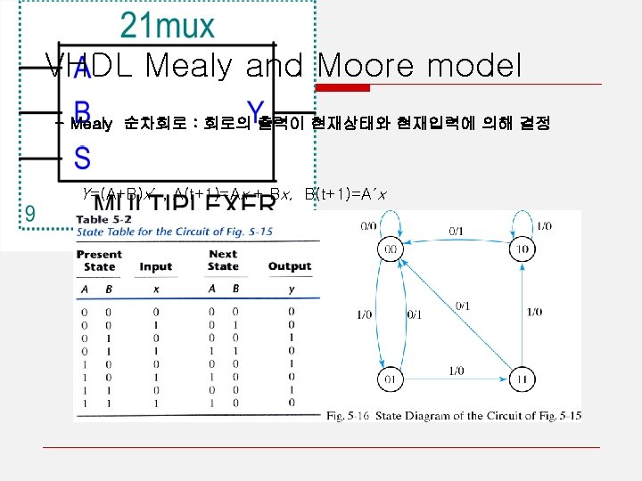
 의 종류 - Mealy 순차회로 : 회로의")
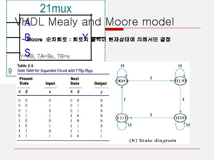
 의 종류 - Moore 순차회로 : 회로의")

 Next State")

")


 BEGIN if( state=")


- Slides: 18
VHDL Mealy and Moore model 순차논리회로 (FSM) 의 종류 - Mealy 순차회로 : 회로의 출력이 현재상태와 현재입력에 의해 결정 Current State Next State Logic Inputs (combinational) Next State Current state Register (sequential) Asynchronous reset Output Logic (combinational) Outputs
VHDL Mealy and Moore model 순차논리회로 (FSM) 의 종류 - Moore 순차회로 : 회로의 출력이 현재상태에 의해서만 결정 Current State Next State Logic Inputs (combinational) Next State Current state Register (sequential) Asynchronous reset Output Logic (combinational) Outputs
VHDL Mealy and Moore model FSM 을 위한 VHDL 기술은 두 부분으로 나누어 진다. 1. A Combinatorial part – input signal이 바뀔 때 마다 동작한다. (Sensitivity list - input signals, state) comb : process (input_signals, state). . . if (input = ” 01”) then a. output: =. . . a. next_state: =. . 2. A sequential part – Clock 이 바뀔 때 마다 동작한다. (Sensityivity list - only clock or clock, reset) seq : process(clk). . . If (clk’event) and (clk = ’ 1’) then. . . VHDL 구문
VHDL Mealy and Moore model Current State Next State Logic Inputs (combinational) Next State Current state Register (sequential) Output Logic Outputs (combinational) 2개 (blue and red) 혹은 3개의 Process (red) 문으로 회로를 표현 가능
VHDL Mealy and Moore model FSM 을 위한 VHDL 기술 방법. - Process 문을 이용하여 Logic 및 Register의 동작을 표시 - State의 데이터 type는 열거형 (enumeration type) 사용 - 초기상태를 반드시 규정: reset conditions - next state로 의 전이(transition)은 case 문사용 - 입력 조건은 if~else 을 사용 - feedback 엔 signal 과 변수 모두 사용 가능
VHDL Mealy and Moore model Sequential description ARCHITECTURE behave OF d_register IS BEGIN PROCESS(clk) BEGIN IF clk’EVENT AND (clk=‘ 1’) THEN q<=D; END IF; END PROCESS; END behave;
VHDL Mealy and Moore model CLK 의 표현 방법 1. IF 문을 이용한 CLK 의 표현 if if SIGNAL’event and SIGNAL = ’ 1’ -- rising edge NOT SIGNAL’stable and SIGNAL = ’ 1’ -- rising edge SIGNAL’event and SIGNAL = ’ 0’ -- falling edge NOT SIGNAL’stable and SIGNAL = ’ 0’ -- falling edge 2. Wait 문을 이용한 CLK 의 표현 wait until CLK = ’ 1’; -- rising edge triggered wait until CLK = ’ 0’; --falling edge triggered
VHDL Mealy and Moore model Mealy Machine Example 0/00 입력 : I 출력 : Y 1, Y 2 S 0 2 개의 process 문을 이용하여 표현 0/01 1/10 S 1 1/00
VHDL Mealy and Moore model Library ieee; Use ieee. std_logic_1164. all; ENTITY Meal IS PORT(clk : IN STD_LOGIC; reset : IN STD_LOGIC; I : IN STD_LOGIC; Y 1, Y 2 : OUT STD_LOGIC); END Meal; ARCHITECTURE a OF Meal IS TYPE STATE_TYPE IS (s 0, s 1); SIGNAL state: STATE_TYPE; BEGIN PROCESS (clk, reset) BEGIN IF reset = '0' THEN state <= s 0; ELSIF clk'EVENT AND clk = '1' THEN CASE state IS WHEN s 0 => IF I='1' THEN state <= s 1; ELSE state <= s 0; END IF; WHEN others => IF I='0' THEN state <= s 0; ELSE state <= s 1; END IF; END CASE;
VHDL Mealy and Moore model END IF; END PROCESS; PROCESS(state, I) BEGIN if( state= s 0 and I='1') then Y 1 <='1'; else Y 1 <='0'; end if; if( state= s 1 and I='0') then Y 2 <='1'; else Y 2 <='0'; end if; END PROCESS; END a;
VHDL Mealy and Moore model Moore Machine Example 0 S 0 000 입력 : I 출력 : Y(2: 0) 2 개의 process 문을 이용하여 표현 1 0 1 S 1 010 1 S 2 101
VHDL Mealy and Moore model Library ieee; Use ieee. std_logic_1164. all; ENTITY Moor IS PORT(clk : IN STD_LOGIC; reset : IN STD_LOGIC; I : IN STD_LOGIC; y : OUT STD_LOGIC_vector(2 downto 0)); END Moor; ARCHITECTURE a OF Moor IS TYPE STATE_TYPE IS (s 0, s 1, s 2); SIGNAL state: STATE_TYPE; BEGIN PROCESS (clk, reset) BEGIN IF reset = '0' THEN state <= s 0; ELSIF clk'EVENT AND clk = '1' THEN CASE state IS WHEN s 0 => IF I='1' THEN state <= s 1; ELSE state <= s 0; END IF;
VHDL Mealy and Moore model WHEN s 1 => IF I='1' THEN state <= s 2; ELSE state <= s 1; END IF; WHEN others => IF I='1' THEN state <= s 0; ELSE state <= s 2; END IF; END CASE; END IF; END PROCESS; PROCESS (state) BEGIN CASE state IS WHEN s 0 => y <= "000"; WHEN s 1 => y <= "010"; WHEN others => y <= "101"; END CASE; END PROCESS; END a;
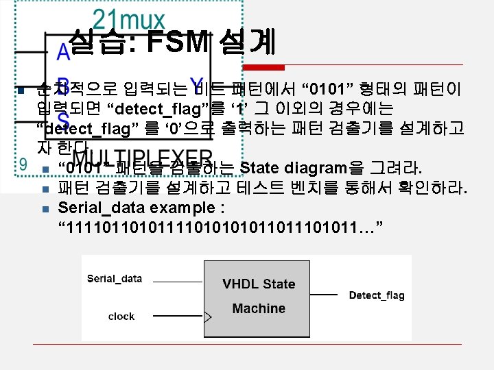
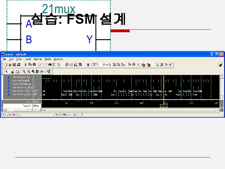
실습: FSM 설계 0 0 0 1 idle ----0 0 0 1 tap 1 -----0 tap 2 -----0 1 tap 3 -----0 tap 4 -----1 1 1