VHDL Introduction 1 VHDLs History o Very High

 Hardware Description Language (VHDL) is")
 The language were first generated in 1981 under the VHSIC")
 o In December 1987, VHDL became IEEE Standard 1076 -")


 signal types: n bit n boolean n integer")


: architecture arch_name of my_ckt is begin")

: architecture behav_conc of my_ckt is signal Xtmp:")


 23")
 24")
 25")
")
 27")
")
 29")
 30")
 31")
- Slides: 31
VHDL - Introduction 1
VHDL’s History o Very High Speed Integrated Circuit (VHSIC) Hardware Description Language (VHDL) is the product of a US Government request for a new means of describing digital hardware. o The VHSIC Program was an initiative of the Defence Department to push the state of the art in VLSI technology, and VHDL was proposed as a versatile hardware description language.
VHDL’s History (Cont. ) The language were first generated in 1981 under the VHSIC program. A number of U. S. companies were involved in designing VHSIC chips for the Department of Defense (Do. D). In July 1983, a team of Intermetrics, IBM and Texas Instruments were awarded a contract to develop VHDL In August 1985, the final version of the language under government contract was released: VHDL Version 7. 2
VHDL’s History (Cont. ) o In December 1987, VHDL became IEEE Standard 1076 - 1987 and in 1988 an ANSI standard o In September 1993, VHDL was restandardized to clarify and enhance the language (IEEE Standard 10761993) o VHDL has been accepted as a Draft International Standard by the IEC (International Engineering Consortium).
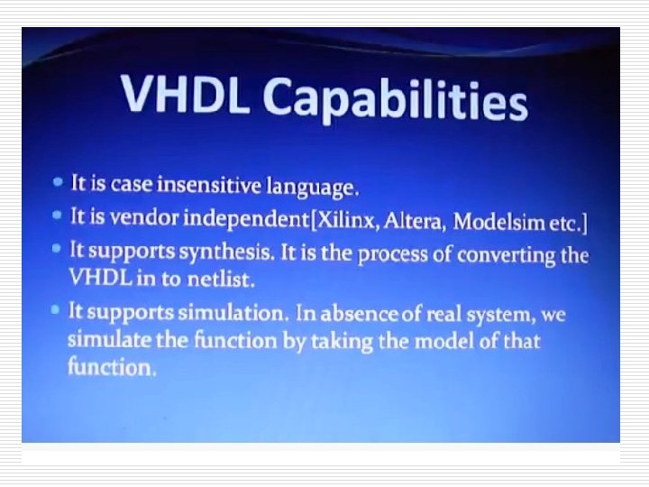
Applications of HDL o Model and document digital systems n Different levels of abstraction o Behavioral, structural, etc. o Verify design o Synthesize circuits n Convert from higher abstraction levels to lower abstraction levels Fall 08, Oct 29 ELEC 2200 -002 Lecture 7 (updated) 7
Input-Output specification of circuit o Example: my_ckt n Inputs: A, B, C n Outputs: X, Y o VHDL description: A B S Fall 08, Oct 29 X my_ckt Y entity my_ckt is port ( A: in bit; B: in bit; S: in bit; X: out bit; Y: out bit); end my_ckt ; ELEC 2200 -002 Lecture 7 (updated) 8
VHDL entity o entity my_ckt port ( A: in B: in S: in X: out Y: out ); end my_ckt; Port names or Signal names Fall 08, Oct 29 is bit; bit § § § A B § Datatypes: Name of the circuit § In-built User-defined § User-defined Filename same as circuit name recommended Example: X § Circuit name: my_ckt § Filename: my_ckt. vhd Y S Direction of port 3 main types: § in: Input out: Output Note the§ absence of semicolon § inout: Bidirectional “; ” at the end of the last signal and the presence at the end of the closing bracket ELEC 2200 -002 Lecture 7 (updated) 9
Built-in Datatypes o Scalar (single valued) signal types: n bit n boolean n integer n Examples: o A: in bit; o G: out boolean; o K: out integer range -2**4 to 2**4 -1; o Aggregate (collection) signal types: n bit_vector: array of bits representing binary numbers n signed: array of bits representing signed binary numbers n Examples: o D: in bit_vector(0 to 7); o E: in bit_vector(7 downto 0); o M: in signed (4 downto 0); --signed 5 bit_vector binary number Fall 08, Oct 29 ELEC 2200 -002 Lecture 7 (updated) 10
User-defined datatype o Construct datatypes arbitrarily or using built-in datatypes o Examples: n type temperature is (high, medium, low); n type byte is array(0 to 7) of bit; Fall 08, Oct 29 ELEC 2200 -002 Lecture 7 (updated) 11
Functional specification o Example: n Behavior for output X: o When S = 0 X <= A o When S = 1 X <= B n Behavior for output Y: o When X = 0 and S =0 Y <= ‘ 1’ o Else Y <= ‘ 0’ Fall 08, Oct 29 A B X my_ckt Y S ELEC 2200 -002 Lecture 7 (updated) 12
VHDL Architecture o o VHDL description (sequential behavior): architecture arch_name of my_ckt is begin p 1: process (A, B, S) begin if (S=‘ 0’) then X <= A; else X <= B; end if; if ((X = ‘ 0’) and (S = ‘ 0’)) then Y <= ‘ 1’; else Y <= ‘ 0’; end if; Error: Signals defined as output ports can only be driven and not read end process p 1; end; Fall 08, Oct 29 ELEC 2200 -002 Lecture 7 (updated) 13
VHDL Architecture architecture behav_seq of my_ckt is signal Xtmp: bit; begin p 1: process (A, B, S, Xtmp) begin if (S=‘ 0’) then Xtmp <= A; else Xtmp <= B; end if; Signals can only be defined in this place before the begin keyword General rule: Include all signals in the sensitivity list of the process which either appear in relational if ((Xtmp = ‘ 0’) and (S = ‘ 0’)) then comparisons or on the right side of Y <= ‘ 1’; the assignment operator inside the process construct. else Y <= ‘ 0’; In our example: Xtmp and S occur in relational end if; comparisons A, B and Xtmp occur on the right side of X <= Xtmp; end process p 1; the assignment operators end; Fall 08, Oct 29 ELEC 2200 -002 Lecture 7 (updated) 14
VHDL Architecture o VHDL description (concurrent behavior): architecture behav_conc of my_ckt is signal Xtmp: bit; begin Xtmp <= A when (S=‘ 0’) else B; Y <= ‘ 1’ when ((Xtmp = ‘ 0’) and (S = ‘ 0’)) else ‘ 0’; X <= Xtmp; end ; Fall 08, Oct 29 ELEC 2200 -002 Lecture 7 (updated) 15
Signals vs Variables o Signals n Signals follow the notion of ‘event scheduling’ n An event is characterized by a (time, value) pair n Signal assignment example: X <= Xtmp; means Schedule the assignment of the value of signal Xtmp to signal X at (Current time + delta) where delta: infinitesimal time unit used by simulator for processing the signals Fall 08, Oct 29 ELEC 2200 -002 Lecture 7 (updated) 16
Signals vs Variables o Variables n Variables do not have notion of ‘events’ n Variables can be defined and used only inside the process block and some other special blocks. n Variable declaration and assignment example: process (…) Variables can only variable K : bit; be defined and used inside the process begin … construct and can -- Assign the value of signal L to var. K be defined only in immediately this place K : = L; … end process; Fall 08, Oct 29 ELEC 2200 -002 Lecture 7 (updated) 17
Simulation o Simulation is modeling the output response of a circuit to given input stimuli o For our example circuit: n Given the values of A, B and S n Determine the values of X and Y o Many types of simulators used n Event driven simulator is used n A B X my_ckt Y S popularly Simulation tool we shall use: Model. Sim Fall 08, Oct 29 ELEC 2200 -002 Lecture 7 (updated) 18
Simulation architecture behav_seq of my_ckt is signal Xtmp: bit; begin p 1: process (A, B, S, Xtmp) variable Xtmp. Var: bit; begin if (S=‘ 0’) then Xtmp <= A; else Xtmp <= B; end if; Time ‘T’ A B S Xtmp Y Xtmp. Var X 0 - U U U ‘X’ ‘X’ 0 0 1 0 ‘X’ ‘X’ 0+d 0 1 0 0 ‘X’ 0+2 d 0 1 0 0 1+d 0 1 1 1 0 0 1 if ((Xtmp = ‘ 0’) and (S = ‘ 0’)) then 1+2 d Y <= ‘ 1’; else Y <= ‘ 0’; Scheduled events end if; X <= Xtmp; Xtmp. Var : = Xtmp; end process p 1; end; Fall 08, Oct 29 executed: list: Xtmp = 0= (0, 0+d) Xtmp Y =Y 1 0= (0, 0+d) X =X 0 ‘X’ = (‘X’, 0+d) Assignments executed: ELEC 2200 -002 Xtmp. Var = 0 Lecture 7 (updated) Assignments Scheduled events executed: Xtmp. Var = ‘X’ list: Xtmp = (0, 0+2 d) (empty) Y = (1, 0+2 d) X = (‘ 0’, 0+2 d) 19
Synthesis o Synthesis: Conversion of behavioral level description to structural level netlist n Abstract behavioral description maps to concrete logic-level implementation n For ex. Integers at behavioral level mapped to bits at structural level o Structural level netlist n Implementation of behavioral description n Describes interconnection of gates o Synthesis tool we shall use: Leonardo Spectrum Fall 08, Oct 29 ELEC 2200 -002 Lecture 7 (updated) 20
Structural level netlist o Behavior of our example circuit: A n Behavior for output X: o When S = 0 B X <= A o When S = 1 X <= B n Behavior for output Y: o When X = 0 and S =0 Y <= 1 o Else Y <= 0 Fall 08, Oct 29 X my_ckt Y S o Logic functions n Sbar = ~ S n Xbar = ~ X n X = A*(Sbar) + B*S n Y = (Xbar)*(Sbar) ELEC 2200 -002 Lecture 7 (updated) 21
Structural level netlist architecture behav_conc of my_ckt is -- component declarations signal Sbar, Xbar, W 1, W 2: bit; o Gate level VHDL descriptions (and, or, etc) are described separately o Design in which other design descriptions are included is called a “hierarchical design” o A VHDL design is included in current design using port map statement begin G 1: G 2: G 3: G 4: not and or port map(Sbar, S); map(W 1, A, Sbar); map(W 2, B, S); map(X, W 1, W 2); G 5: not port map(Xbar, X); G 6: and port map(Y, Xbar, Sbar); end ; Fall 08, Oct 29 ELEC 2200 -002 Lecture 7 (updated) 22
AND GATE Fall 08, Oct 29 ELEC 2200 -002 Lecture 7 (updated) 23
XOR Fall 08, Oct 29 ELEC 2200 -002 Lecture 7 (updated) 24
OR GATE Fall 08, Oct 29 ELEC 2200 -002 Lecture 7 (updated) 25
4 X 1 MUX Fall 08, Oct 29 ELEC 2200 -002 Lecture 7 (updated) 26
Fall 08, Oct 29 ELEC 2200 -002 Lecture 7 (updated) 27
DECODER 2 X 4 Fall 08, Oct 29 ELEC 2200 -002 Lecture 7 (updated) 28
Fall 08, Oct 29 ELEC 2200 -002 Lecture 7 (updated) 29
Fall 08, Oct 29 ELEC 2200 -002 Lecture 7 (updated) 30
Fall 08, Oct 29 ELEC 2200 -002 Lecture 7 (updated) 31