VHDL Description 1 Behavioral Description Functional or Algorithm
 - Functional or Algorithm Description - High Level")
VHDL Description 1. Behavioral Description (동작묘사) - Functional or Algorithm Description - High Level Language Program 과 유사 - 문서화를 위해서 우수 - VHDL의 순 차문 (Process) 사용 2. Dataflow Description (데이터 흐름 묘사) - Behavioral Description보다 한 단계 낮은 Level - Boolean Function, RTL, 또는 연산자 (AND, OR) 표현 3. Structural Description (구조묘사) - 가장 하드웨어적 표현에 가까움 - 구성요소 (component) 및 연결(port) 까지 표현 - 합성을 위해 사용 4. Mixed Description (복합묘사) - 지금까지 기술된 방식을 혼합적으로 사용 - Simulation 및 합성 가능

1. VHDL Description 1. two 입력 AND gate Library ieee; Use ieee. std_logic_1164. all; Entity and_2 is port( a, b : in std_logic; y : out std_logic ); end and_2; Architecture dataflow of and_2 is begin y <= a and b; end dataflow;

1. VHDL Description 2. two-입력 OR gate Library ieee; Use ieee. std_logic_1164. all; Entity or_2 is port( a, b : in std_logic; y : out std_logic ); end or_2; Architecture dataflow of or_2 is begin y <= a or b; end dataflow;
 or C 3 -2. OR-AND-Signal")
1. VHDL Description 3 -1 AND-OR-Signal Y=(a and b) or C 3 -2. OR-AND-Signal Y=(a or b) and C

1. VHDL Description AND-OR-Signal, OR-AND-Signal 의 data flow 표현 Library ieee; Use ieee. std_logic_1164. all; Entity ANDORS is port ( A, B, C : in std_logic; Y : out std_logic ); End ANDORS; Library ieee; Use ieee. std_logic_1164. all; Entity ORANDS is port ( A, B, C : in std_logic; Y : out std_logic ); End ORANDS; Architecture dataflow of ANDORS is signal aandb : std_logic; Begin aandb <= A and B; Y <= a and b or C End dataflow; Architecture dataflow of ORANDS is signal aorb : std_logic; Begin aorb <= A or B; Y <= a or b and C End dataflow;

1. VHDL Description 4. 4 -bits OR gate library ieee; use ieee. std_logic_1164. all; entity or_4 bits is port( a, b : in std_logic_vector(3 downto 0); y : out std_logic_vector(3 downto 0) ); end or_4 bits; architecture dataflow of or_4 bits is begin y <= a or b; end dataflow; a b y

1. VHDL Description 5. 2 x 1 Mux 의 behavioral description library ieee; use ieee. std_logic_1164. all; entity mux 21 is port( a, b : in std_logic; s : in std_logic; x : out std_logic); end mux 21; Architecture select_1 OF mux 21 IS BEGIN mu: PROCESS (a, b, s) BEGIN IF s = '0' THEN x <= a; ELSE x <= b; END IF; END PROCESS mu; END select_1 a b MUX x S x <= a when (s='0') else b;

1. VHDL Description 5 -1. 2 x 1 Mux 의 behavioral description ; Case 문을 이용한 표현 case s is when '0' => x<= a; when others => x<= b; end case; 5 -2. 2 x 1 Mux 의 behavioral description ; With Select 문을 이용한 표현 WITH s SELECT x <= a WHEN ‘ 0’, b WHEN others;

1. VHDL Description 6. Half-adder x y half adder S=xy′+x′y C=xy S : sum C : carry

1. VHDL Description 6 -1. Half-adder dataflow description library ieee; Use ieee. std_logic_1164. all; Entity half_add is port( a, b : in std_logic; s, c : out std_logic); end half_add; Architecture RTL_1 of half_add is begin S <= A xor B; C <= A and B; end RTL_1;

1. VHDL Description 6 -2. Half-adder behavior description architecture Beh of half_add is begin process begin if (a = b) then S <= ‘ 0’ ; else S <= ‘ 1’ ; end if ; if (a = ‘ 1') and (b = ‘ 1’) then C <= ‘ 1’ ; else C <= ‘ 0’ ; end if ; end process ; end Beh ;

1. VHDL Description 7. Full Adder x y Cin cin full adder Sum Cout cout Sum=x’yz+xy’z’+xyz Cout=xy+xz+yz=xy+xy’z+z’yz

1. VHDL Description Signal 지정필요 7. Full Adder t 1 sum t 2 Half Adder t 3 cout cin

1. VHDL Description 7 -1. Full Adder dataflow description library ieee; use ieee. std_logic_1164. all; entity full_add is port( x, y, Cin : in std_logic; sum, Cout : out std_logic); end full_add; architecture fadd of full_add is signal t 1, t 2, t 3 : std_logic; begin t 1 <= a xor b; t 2 <= a and b; t 3 <= t 1 and cin; sum <= t 1 xor cin; cout <= t 2 or t 3; end fadd;

1. VHDL Description 7 -2. Full Adder Behavior description architecture beh of full_add is begin process variable I : integer ; x, y, cin이 되는 개수를 센다 begin I : = 0; if (x = ‘ 1’) then I : = I + 1 ; end if; if (y = ‘ 1’) then I : = I + 1 ; end if; if (Cin = ‘ 1’) then I : = I + 1 ; end if; if (I = 1) or (I = 3) then Sum <= ‘ 1’ ; else Sum <= ‘ 0’; end if; if (I > 1) then Cout <= ‘ 1’ ; else Cout <= ‘ 0’; end if; wait on x, y, Cin ; end process ; end beh ;

1. VHDL Description 7 -3. Full Adder Structural description library ieee; use ieee. std_logic_1164. all; use ieee. std_unsigned. all; use ieee. std_logic_arith. all; Component half_add port (A, B : in std_logic; S, C: out std_logic); End Component entity full_add is port( x, y, Cin : in std_logic; sum, Cout : out std_logic); end full_add; Begin HA 1: Half_add port map(X, Y, t 1, t 2); HA 2: Half_add port map(t 1, Cin, sum, t 3); ORG: OR_3 port map(t 2, t 3, Cout) end fadds; architecture fadds of full_add is signal t 1, t 2, t 3 : std_logic; Component OR_3 port (I 1, I 2 : in std_logic; O : out std_logic End Component
’ : A와B 가 같으면 1을")
1. VHDL Description 8. Comparator Y= (A XOR B)’ : A와B 가 같으면 1을 출력, 틀리면 0을 출력 library ieee; use ieee. std_logic_1164. all; entity comp is port( A, B, Cin : in std_logic; Y : out std_logic); end comp; architecture compdata of comp is begin Y <= not(a xor b); end compdata;
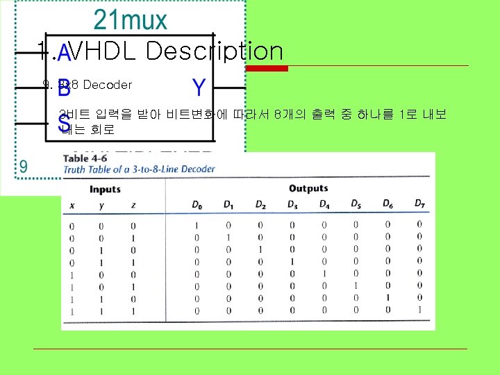

1. VHDL Description 9. 3 x 8 Decoder Behavioral description LIBRARY ieee; USE ieee. std_logic_1164. all; ENTITY decoder 3_8 IS PORT( xyz : IN D : OUT END decoder 3_8 ; STD_LOGIC_VECTOR (2 downto 0); STD_LOGIC_VECTOR (7 downto 0)); ARCHITECTURE Beha OF decoder 3_8 IS BEGIN WITH xyz SELECT y<="00000001" WHEN "000", "00000010" WHEN "001", "00000100" WHEN "010", "00001000" WHEN "011", "00010000" WHEN "100", "00100000" WHEN "101", "01000000" WHEN "110", "10000000" WHEN "111", "0000" WHEN others; END beha;
- Slides: 19