
VHDL 2 Identifiers data objects and data types

VHDL 2 Identifiers, data objects and data types Chapter 2 Identifiers Data objects Data types constants Signals Variables VHDL 2. Identifiers, data objects and data types ver. 6 a 1
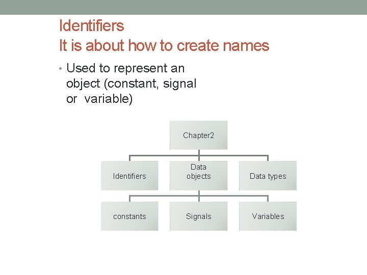
Identifiers It is about how to create names • Used to represent an object (constant, signal or variable) Chapter 2 Identifiers Data objects Data types constants Signals Variables VHDL 2. Identifiers, data objects and data types ver. 6 a 2
VHDL 2. Identifiers, data objects and data types ver. 6 a 3 Rules for Identifiers • Names for users to identify data objects: signals, variables etc. • First character must be a letter • last character cannot be an underscore • Not case sensitive • Two connected underscores are not allowed • Examples of identifiers: a, b, c, axy, clk. . .
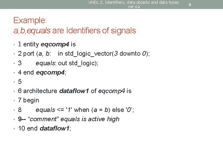
VHDL 2. Identifiers, data objects and data types ver. 6 a Example: a, b, equals are Identifiers of signals • 1 entity eqcomp 4 is • 2 port (a, b: • • in std_logic_vector(3 downto 0); 3 equals: out std_logic); 4 end eqcomp 4; 5 6 architecture dataflow 1 of eqcomp 4 is 7 begin 8 equals <= '1' when (a = b) else '0’; 9 -- “comment” equals is active high 10 end dataflow 1; 4
VHDL 2. Identifiers, data objects and data types ver. 6 a DATA OBJECTS 5
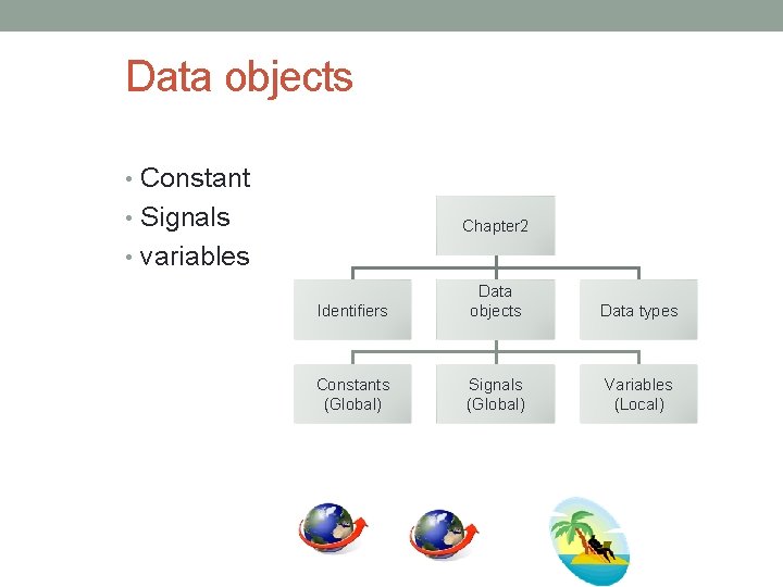
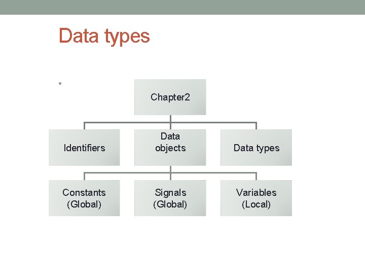
Data objects • Constant • Signals Chapter 2 • variables Identifiers Data objects Data types Constants (Global) Signals (Global) Variables (Local) VHDL 2. Identifiers, data objects and data types ver. 6 a 6
VHDL 2. Identifiers, data objects and data types ver. 6 a 7 Data objects: 3 different objects • 1 Constants: hold values that cannot be changed within a design. • e. g. constant width: integer : =8 • 2 Signals: to represent wire connections • e. g. signal count: bit_vector (3 downto 0) • -- count means 4 wires; they are count(3), count(2), count(1), count(0). • 3 Variables: internal representation used by programmers; do not exist physically.
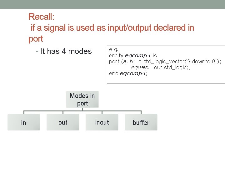
Recall: if a signal is used as input/output declared in port e. g. entity eqcomp 4 is port (a, b: in std_logic_vector(3 downto 0 ); equals: out std_logic); end eqcomp 4; • It has 4 modes Modes in port in out inout buffer VHDL 2. Identifiers, data objects and data types ver. 6 a 8
VHDL 2. Identifiers, data objects and data types ver. 6 a SYNTAX TO CREATE DATA OBJECTS In entity declarations 9
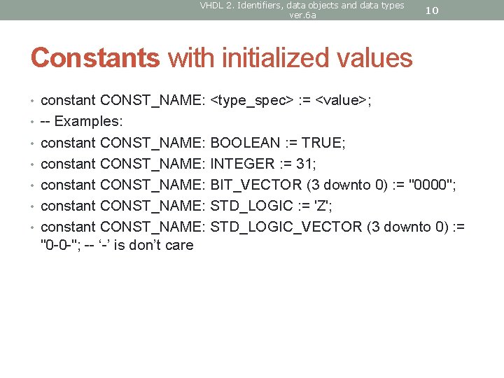
VHDL 2. Identifiers, data objects and data types ver. 6 a 10 Constants with initialized values • constant CONST_NAME: <type_spec> : = <value>; • -- Examples: • constant CONST_NAME: BOOLEAN : = TRUE; • constant CONST_NAME: INTEGER : = 31; • constant CONST_NAME: BIT_VECTOR (3 downto 0) : = "0000"; • constant CONST_NAME: STD_LOGIC : = 'Z'; • constant CONST_NAME: STD_LOGIC_VECTOR (3 downto 0) : = "0 -0 -"; -- ‘-’ is don’t care
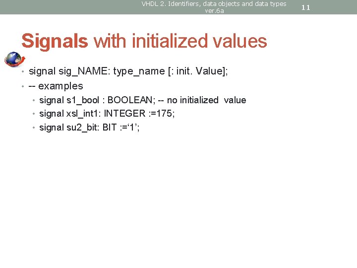
VHDL 2. Identifiers, data objects and data types ver. 6 a Signals with initialized values • signal sig_NAME: type_name [: init. Value]; • -- examples • signal s 1_bool : BOOLEAN; -- no initialized value • signal xsl_int 1: INTEGER : =175; • signal su 2_bit: BIT : =‘ 1’; 11
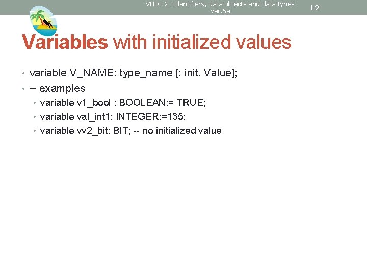
VHDL 2. Identifiers, data objects and data types ver. 6 a Variables with initialized values • variable V_NAME: type_name [: init. Value]; • -- examples • variable v 1_bool : BOOLEAN: = TRUE; • variable val_int 1: INTEGER: =135; • variable vv 2_bit: BIT; -- no initialized value 12

VHDL 2. Identifiers, data objects and data types ver. 6 a Signal and variable assignments • SIG_NAME <= <expression>; • VAR_NAME : =<expression>; 13
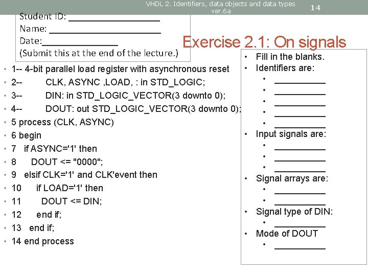
VHDL 2. Identifiers, data objects and data types ver. 6 a Student ID: _________ Name: ___________ Date: ________ (Submit this at the end of the lecture. ) • • • • 14 Exercise 2. 1: On signals • Fill in the blanks. • Identifiers are: 1 -- 4 -bit parallel load register with asynchronous reset • _____ 2 -CLK, ASYNC , LOAD, : in STD_LOGIC; • _____ 3 -DIN: in STD_LOGIC_VECTOR(3 downto 0); • _____ 4 -DOUT: out STD_LOGIC_VECTOR(3 downto 0); • _____ 5 process (CLK, ASYNC) • _____ • Input signals are: 6 begin • _____ 7 if ASYNC='1' then • _____ 8 DOUT <= "0000"; • _____ 9 elsif CLK='1' and CLK'event then • Signal arrays are: 10 if LOAD='1' then • __________ 11 DOUT <= DIN; • Signal type of DIN: 12 end if; • _____ 13 end if; • Mode of DOUT 14 end process • _____
VHDL 2. Identifiers, data objects and data types ver. 6 a Data types • Different types of wires • Each type has a certain range of logic levels 15
Data types • Chapter 2 Identifiers Data objects Data types Constants (Global) Signals (Global) Variables (Local) VHDL 2. Identifiers, data objects and data types ver. 6 a 16
VHDL 2. Identifiers, data objects and data types ver. 6 a Data types • User can design the type for a data object. • E. g. a signal can have the type ‘bit’ • E. g. a variable can have the type ‘std_logic’ • Only same type can interact. 17
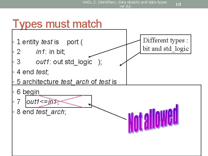
VHDL 2. Identifiers, data objects and data types ver. 6 a 18 Types must match • 1 entity test is • 2 port ( in 1: in bit; • 3 out 1: out std_logic ); • 4 end test; • 5 architecture test_arch of test is • 6 begin • 7 out 1<=in 1; • 8 end test_arch; Different types : bit and std_logic
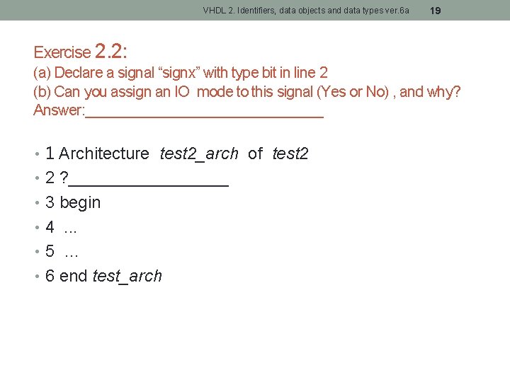
VHDL 2. Identifiers, data objects and data types ver. 6 a 19 Exercise 2. 2: (a) Declare a signal “signx” with type bit in line 2 (b) Can you assign an IO mode to this signal (Yes or No) , and why? Answer: _______________ • 1 Architecture test 2_arch of test 2 • 2 ? _________ • 3 begin • 4. . . • 5 … • 6 end test_arch
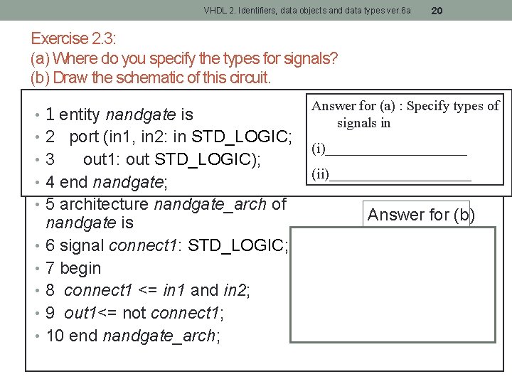
VHDL 2. Identifiers, data objects and data types ver. 6 a 20 Exercise 2. 3: (a) Where do you specify the types for signals? (b) Draw the schematic of this circuit. • 1 entity nandgate is • 2 port (in 1, in 2: in STD_LOGIC; • 3 out 1: out STD_LOGIC); • 4 end nandgate; • 5 architecture nandgate_arch of nandgate is • 6 signal connect 1: STD_LOGIC; • 7 begin • 8 connect 1 <= in 1 and in 2; • 9 out 1<= not connect 1; • 10 end nandgate_arch; Answer for (a) : Specify types of signals in (i)__________ (ii)__________ Answer for (b)
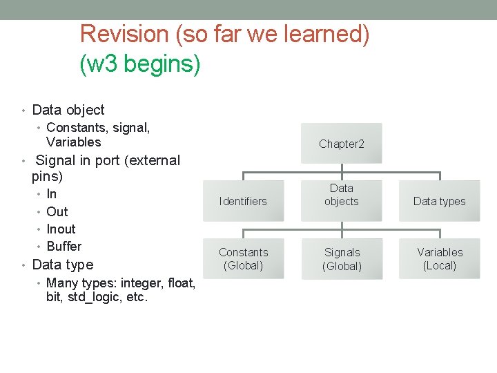
Revision (so far we learned) (w 3 begins) • Data object • Constants, signal, Variables • Signal in port (external Chapter 2 pins) • In • Out Identifiers Data objects Data types Constants (Global) Signals (Global) Variables (Local) • Inout • Buffer • Data type • Many types: integer, float, bit, std_logic, etc. VHDL 2. Identifiers, data objects and data types ver. 6 a 21
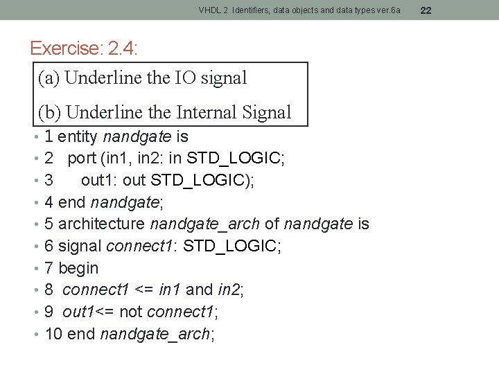
VHDL 2. Identifiers, data objects and data types ver. 6 a Exercise: 2. 4: (a) Underline the IO signal (b) Underline the Internal Signal • 1 entity nandgate is • 2 port (in 1, in 2: in STD_LOGIC; • 3 out 1: out STD_LOGIC); • 4 end nandgate; • 5 architecture nandgate_arch of nandgate is • 6 signal connect 1: STD_LOGIC; • 7 begin • 8 connect 1 <= in 1 and in 2; • 9 out 1<= not connect 1; • 10 end nandgate_arch; 22
VHDL 2. Identifiers, data objects and data types ver. 6 a DIFFERENT DATA TYPES 23
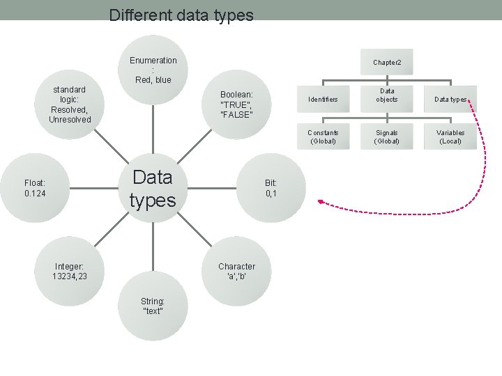
Different data types Enumeration : Red, blue standard logic: Resolved, Unresolved Chapter 2 Boolean: “TRUE”, ”FALSE” • Data types Float: 0. 124 Integer: 13234, 23 Identifiers Data objects Data types Constants (Global) Signals (Global) Variables (Local) Bit: 0, 1 Character ‘a’, ’b’ String: “text” VHDL 2. Identifiers, data objects and data types ver. 6 a 24
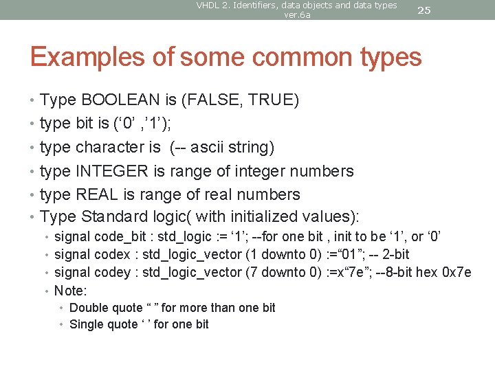
VHDL 2. Identifiers, data objects and data types ver. 6 a 25 Examples of some common types • Type BOOLEAN is (FALSE, TRUE) • type bit is (‘ 0’ , ’ 1’); • type character is (-- ascii string) • type INTEGER is range of integer numbers • type REAL is range of real numbers • Type Standard logic( with initialized values): • signal code_bit : std_logic : = ‘ 1’; --for one bit , init to be ‘ 1’, or ‘ 0’ • signal codex : std_logic_vector (1 downto 0) : =“ 01”; -- 2 -bit • signal codey : std_logic_vector (7 downto 0) : =x“ 7 e”; --8 -bit hex 0 x 7 e • Note: • Double quote “ ” for more than one bit • Single quote ‘ ’ for one bit
VHDL 2. Identifiers, data objects and data types ver. 6 a 26 Boolean, Bit Types • Boolean (true/false), character, integer, real, string, these types have their usual meanings. In addition, VHDL has the types: bit, bit_vector, • The type “bit” can have a value of '0' or '1'. A bit_vector is an array of bits. • See VHDL Quick Reference http: //www. doulos. com/knowhow/vhdl_designers_guide/
VHDL 2. Identifiers, data objects and data types ver. 6 a 27 Integer type (depends on your tool; it uses large amount of logic circuits for the implementation of integer/float operators) E. g. • Range from -(2^31) to (2^31)-1
VHDL 2. Identifiers, data objects and data types ver. 6 a 28 Floating type • -3. 4 E+38 to +3. 4 E+38 • For encoding floating numbers, but usually not supported by synthesis tools of programmable logic because of its huge demand of resources.
VHDL 2. Identifiers, data objects and data types ver. 6 a 29 Enumeration types: • How to input an abstract concept into a circuit ? • E. g. 1 color: red, blue, yellow, orange etc, we need 2 bits • E. g. 2 • Language type: Chinese, English, Spanish, Japanese, Arabic. How many bits needed? • Answer: 5 different combinations: 3 bits • 中文字, Chinese characters, caracteres chinos, 漢字, ﺍﻷﺤﺮﻑ ﺍﻟﺼﻴﻨﻴﺔ ,
VHDL 2. Identifiers, data objects and data types ver. 6 a 30 Enumeration types: • An enumeration type is defined by listing (enumerating) all possible values • Examples: • type COLOR is (BLUE, GREEN, YELLOW, RED); • type MY_LOGIC is (’ 0’, ’ 1’, ’U’, ’Z’); • -- then MY_LOGIC can be one of the 4 values
VHDL 2. Identifiers, data objects and data types ver. 6 a 31 Exercises 2. 5 • Example of the enumeration type of the menu of a restaurant: • type food is (hotdog, tea, sandwich, cake, chick_wing); • (a) Declare the enumeration type of the traffic light. • Answer: ____________________ • (b) Declare the enumeration type of the outcomes of rolling a dice. • Answer: ____________________ • (c) Declare the enumeration type of the 7 notes of music. • Answer: ____________________
VHDL 2. Identifiers, data objects and data types ver. 6 a DEFINE Array or a bus 32
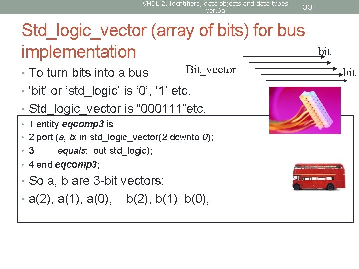
VHDL 2. Identifiers, data objects and data types ver. 6 a 33 Std_logic_vector (array of bits) for bus implementation • To turn bits into a bus Bit_vector • ‘bit’ or ‘std_logic’ is ‘ 0’, ‘ 1’ etc. • Std_logic_vector is “ 000111”etc. • 1 entity eqcomp 3 is • 2 port (a, b: in std_logic_vector(2 downto 0); • 3 equals: out std_logic); • 4 end eqcomp 3; • So a, b are 3 -bit vectors: • a(2), a(1), a(0), b(2), b(1), b(0), bit
VHDL 2. Identifiers, data objects and data types ver. 6 a 34 Exercise 2. 6 Difference between “to” and “downto” • (a) Given: signal a : std_logic_vector( 2 downto 0); • Create a 3 -bit bus c using “to”instead of “downto” in the declaration. • Answer: _______________ • (b) Draw the circuit for this statement: c<=a;
VHDL 2. Identifiers, data objects and data types ver. 6 a 35 AN ADVANCED TOPIC Resolved, Unresolved logic (Concept of Multi-value logic)
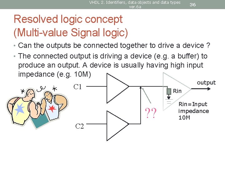
VHDL 2. Identifiers, data objects and data types ver. 6 a 36 Resolved logic concept (Multi-value Signal logic) • Can the outputs be connected together to drive a device ? • The connected output is driving a device (e. g. a buffer) to produce an output. A device is usually having high input impedance (e. g. 10 M) output C 1 Rin ? ? C 2 Rin=Input impedance 10 M
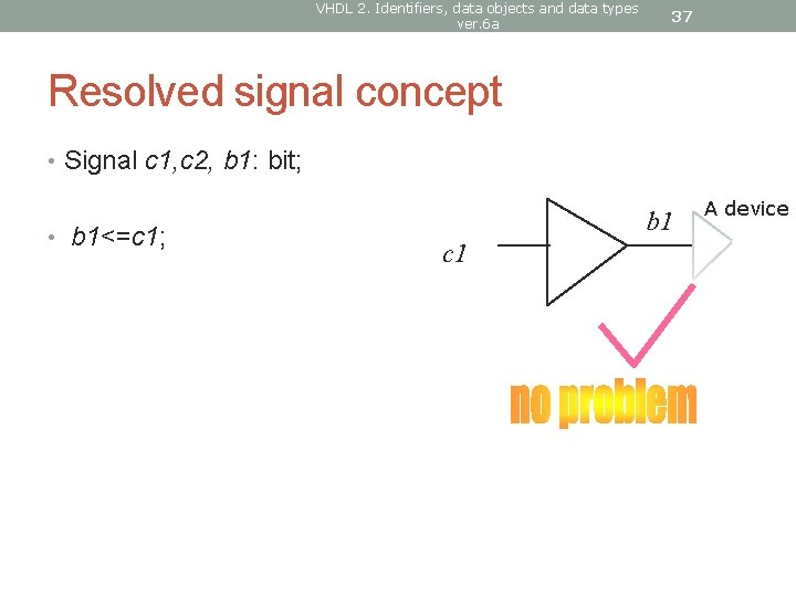
VHDL 2. Identifiers, data objects and data types ver. 6 a 37 Resolved signal concept • Signal c 1, c 2, b 1: bit; • b 1<=c 1; b 1 c 1 A device
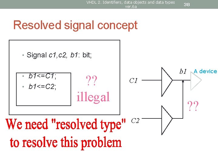
VHDL 2. Identifiers, data objects and data types ver. 6 a 38 Resolved signal concept • Signal c 1, c 2, b 1: bit; • b 1<=C 1; • b 1<=C 2; ? ? illegal b 1 A device C 1 ? ? C 2
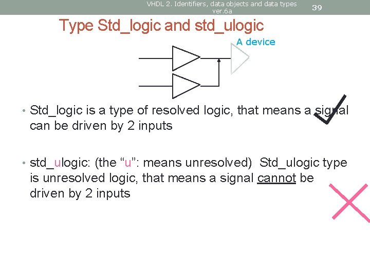
VHDL 2. Identifiers, data objects and data types ver. 6 a 39 Type Std_logic and std_ulogic A device • Std_logic is a type of resolved logic, that means a signal can be driven by 2 inputs • std_ulogic: (the “u”: means unresolved) Std_ulogic type is unresolved logic, that means a signal cannot be driven by 2 inputs
VHDL 2. Identifiers, data objects and data types ver. 6 a 40 Although VHDL allows resolved types, but Xilinx has not implemented it • Error message # 400 • Signal 'name' has multiple drivers. • The compiler has encountered a signal that is being driven in more than one process. • Note that it is legal VHDL to have a signal with multiple drivers if the signals type is a resolved type (i. e. has a resolution function) such as 'std_logic' (but not 'std_ulogic'). (Metamor, Inc. )
VHDL 2. Identifiers, data objects and data types ver. 6 a 41 STANDARD LOGIC TYPE AND RESOLVED LOGIC (MULTI-VALUE SIGNAL TYPES) The IEEE_1164 library -- the industrial standard And some of its essential data types
VHDL 2. Identifiers, data objects and data types ver. 6 a 42 To use the library, add the two lines at the front • Library IEEE • use IEEE. std_logic_1164. all • entity • architecture
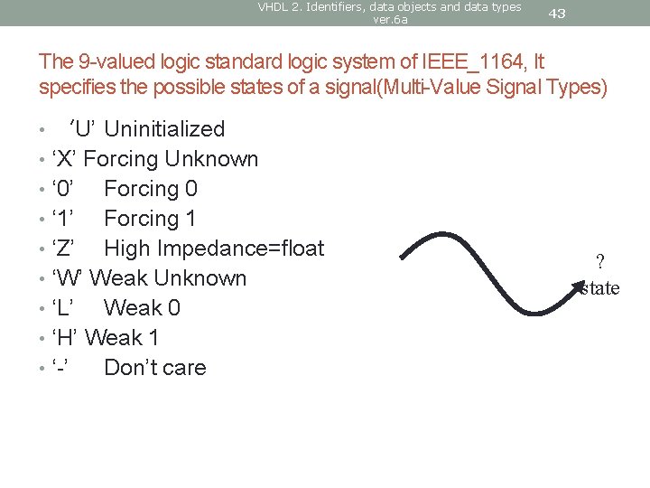
VHDL 2. Identifiers, data objects and data types ver. 6 a 43 The 9 -valued logic standard logic system of IEEE_1164, It specifies the possible states of a signal(Multi-Value Signal Types) • ‘U’ Uninitialized • ‘X’ Forcing Unknown • ‘ 0’ Forcing 0 • ‘ 1’ Forcing 1 • ‘Z’ High Impedance=float • ‘W’ Weak Unknown • ‘L’ Weak 0 • ‘H’ Weak 1 • ‘-’ Don’t care ? state
VHDL 2. Identifiers, data objects and data types ver. 6 a 44 Resolved rules of the 9 -level logic • There are weak unknown, weak 0, weak 1 and force unknown, force 0, force 1 • when 2 signals tight together, the forcing signal dominates. • It is used to model the internal of a device. • In our applications here, the subset of the IEEE forcing values ‘X’ ‘ 0’ ‘ 1’ ‘Z’ are used.
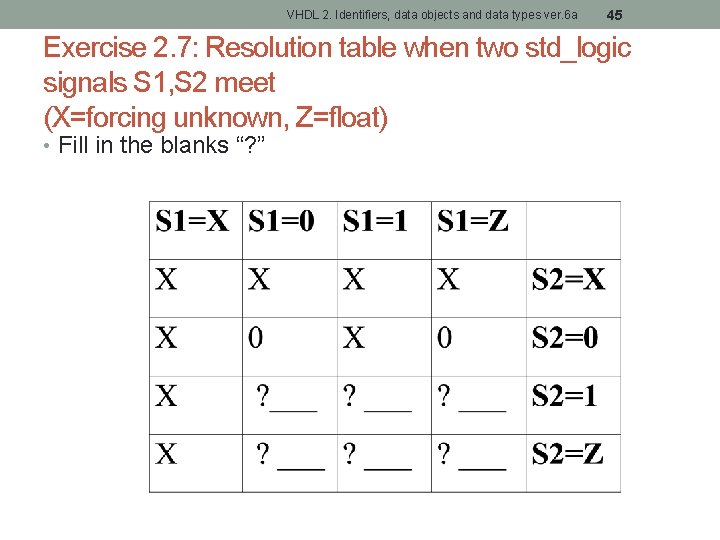
VHDL 2. Identifiers, data objects and data types ver. 6 a 45 Exercise 2. 7: Resolution table when two std_logic signals S 1, S 2 meet (X=forcing unknown, Z=float) • Fill in the blanks “? ”
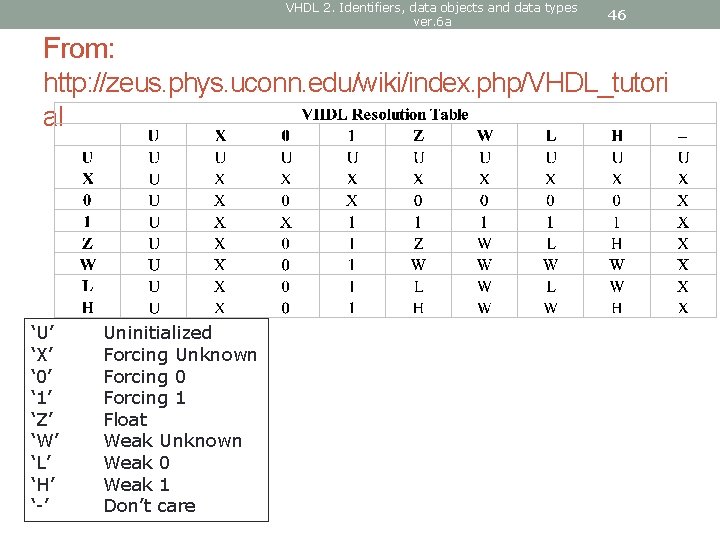
VHDL 2. Identifiers, data objects and data types ver. 6 a 46 From: http: //zeus. phys. uconn. edu/wiki/index. php/VHDL_tutori al ‘U’ ‘X’ ‘ 0’ ‘ 1’ ‘Z’ ‘W’ ‘L’ ‘H’ ‘-’ Uninitialized Forcing Unknown Forcing 0 Forcing 1 Float Weak Unknown Weak 0 Weak 1 Don’t care
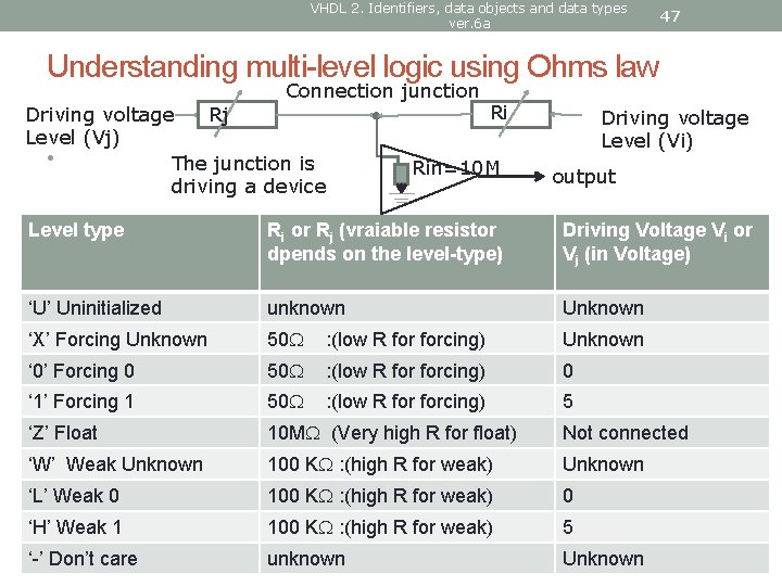
VHDL 2. Identifiers, data objects and data types ver. 6 a 47 Understanding multi-level logic using Ohms law Connection junction Driving voltage Rj Level (Vj) • The junction is driving a device Ri Rin=10 M Driving voltage Level (Vi) output Level type Ri or Rj (vraiable resistor dpends on the level-type) Driving Voltage Vi or Vj (in Voltage) ‘U’ Uninitialized unknown Unknown ‘X’ Forcing Unknown 50 : (low R forcing) Unknown ‘ 0’ Forcing 0 50 : (low R forcing) 0 ‘ 1’ Forcing 1 50 : (low R forcing) 5 ‘Z’ Float 10 M (Very high R for float) Not connected ‘W’ Weak Unknown 100 K : (high R for weak) Unknown ‘L’ Weak 0 100 K : (high R for weak) 0 ‘H’ Weak 1 100 K : (high R for weak) 5 ‘-’ Don’t care unknown Unknown
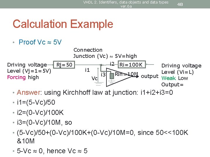
VHDL 2. Identifiers, data objects and data types ver. 6 a 48 Calculation Example • Proof Vc 5 V Connection Junction (Vc) 5 V=high i 2 Ri=100 K Driving voltage Rj=50 Driving voltage i 1 Level (Vj=1=5 V) Rin=10 M output Level (Vi=L) i 3 Forcing high Weak Low Vc Output= • Answer: using Kirchhoff law at junction: i 1+i 2+i 3=0 • i 1=(5 -Vc)/50 • i 2=(0 -Vc)/100 K • i 3=(0 -Vc)/10 M, so • (5 -Vc)/50+(0 -Vc)/100 K+(0 -Vc)/10 M=0, since 50<<100 K &10 M • 5 -Vc 0, hence Vc 5
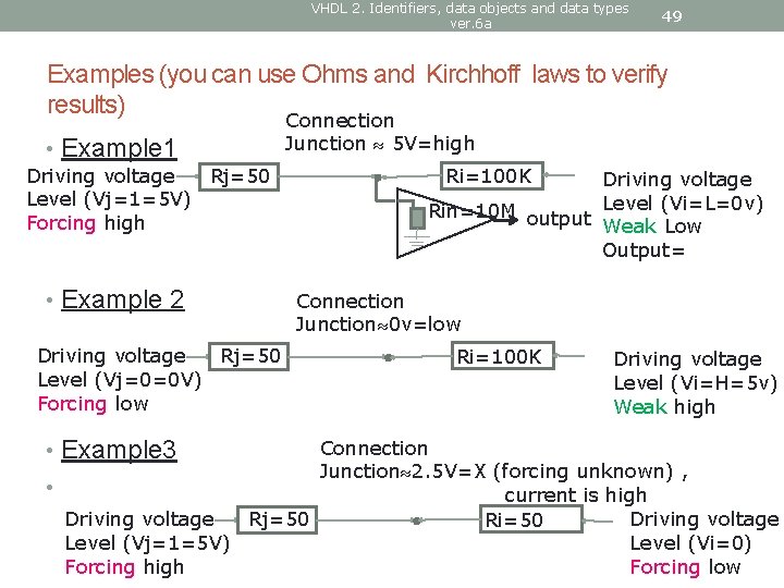
VHDL 2. Identifiers, data objects and data types ver. 6 a 49 Examples (you can use Ohms and Kirchhoff laws to verify results) • Example 1 Driving voltage Rj=50 Level (Vj=1=5 V) Forcing high • Example 2 Driving voltage Rj=50 Level (Vj=0=0 V) Forcing low • Example 3 Connection Junction 5 V=high Ri=100 K Driving voltage Rin=10 M output Level (Vi=L=0 v) Weak Low Output= Connection Junction 0 v=low Ri=100 K Driving voltage Level (Vi=H=5 v) Weak high Connection Junction 2. 5 V=X (forcing unknown) , • current is high Driving voltage Rj=50 Ri=50 Level (Vi=0) Level (Vj=1=5 V) Forcing low Forcing high

VHDL 2. Identifiers, data objects and data types ver. 6 a 50 More examples Connection Junction 0=0 V (Low) , • Example 4 Driving voltage Level (Vj=Z, not connected) Rj=10 M Ri=50 Connection • Example 5 a Junction 2. 5 V=W, weak unknown Driving voltage Ri 1=100 K Rj=100 K Level (Vj=H=5 V), Weak High • Example 5 b Driving voltage Level (Vj=H=5 V), Weak High Connection Junction 0 V=Low, Ri 1=100 K Rj=100 K Ri 2=50 Driving voltage Level (Vi=0) Forcing Low Driving voltage Level (Vi=L=0 V) Weak Low Driving voltage Level (Vi=L=0 V) Forcing Low
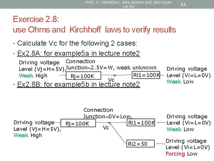
VHDL 2. Identifiers, data objects and data types ver. 6 a 51 Exercise 2. 8: use Ohms and Kirchhoff laws to verify results • Calculate Vc for the following 2 cases: • Ex 2. 8 A: for example 5 a in lecture note 2 Driving voltage Connection Level (Vj=H=5 V), Junction 2. 5 V=W, weak unknown Ri 1=100 K Weak High Rj=100 K Vc • Ex 2. 8 B: for example 5 b in lecture note 2 Connection Junction 0 V=Low, Driving voltage Ri 1=100 K Rj=100 K Vc Level (Vj=H=5 V), Weak High Ri 2=50 Driving voltage Level (Vi=L=0 V) Weak Low Driving voltage Level (Vi=L=0 V) Forcing Low
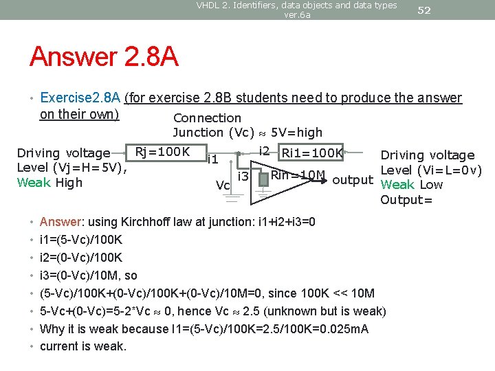
VHDL 2. Identifiers, data objects and data types ver. 6 a 52 Answer 2. 8 A • Exercise 2. 8 A (for exercise 2. 8 B students need to produce the answer on their own) Connection Junction (Vc) 5 V=high i 2 Ri 1=100 K Rj=100 K Driving voltage i 1 Level (Vj=H=5 V), Rin=10 M output Level (Vi=L=0 v) i 3 Weak High Weak Low Vc Output= • Answer: using Kirchhoff law at junction: i 1+i 2+i 3=0 • i 1=(5 -Vc)/100 K • i 2=(0 -Vc)/100 K • i 3=(0 -Vc)/10 M, so • (5 -Vc)/100 K+(0 -Vc)/10 M=0, since 100 K << 10 M • 5 -Vc+(0 -Vc)=5 -2*Vc 0, hence Vc 2. 5 (unknown but is weak) • Why it is weak because I 1=(5 -Vc)/100 K=2. 5/100 K=0. 025 m. A • current is weak.
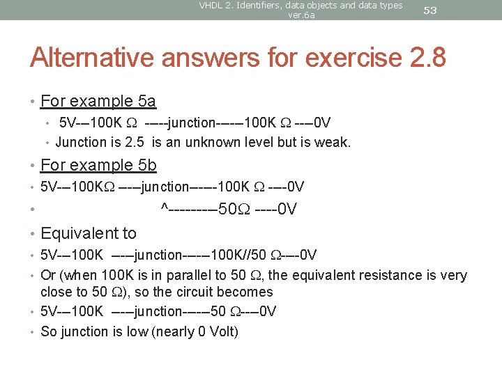
VHDL 2. Identifiers, data objects and data types ver. 6 a 53 Alternative answers for exercise 2. 8 • For example 5 a • 5 V---100 K -----junction------100 K ----0 V • Junction is 2. 5 is an unknown level but is weak. • For example 5 b • 5 V---100 K -----junction------100 K ----0 V • ^-----50 ----0 V • Equivalent to • 5 V---100 K -----junction------100 K//50 ----0 V • Or (when 100 K is in parallel to 50 , the equivalent resistance is very close to 50 ), so the circuit becomes • 5 V---100 K -----junction------50 ----0 V • So junction is low (nearly 0 Volt)
VHDL 2. Identifiers, data objects and data types ver. 6 a 54 Appendix 1 Example of using IEEE 1164 • library IEEE; use IEEE. std_logic_1164. all; -- defines std_logic types --library metamor; entity jcounter is port ( clk : in STD_LOGIC; q : buffer STD_LOGIC_VECTOR (7 downto 0) );
VHDL 2. Identifiers, data objects and data types ver. 6 a 55 Quick Revision • You should have learnt • Identifier and usage • Different data objects (constant, signals, variables) • Different data types (Boolean , bit, stad_logic, std_logic_vector integer etc) • Resolved logic
- Slides: 55