
VERTICAL ALIGNMENT Spring 2020 Vertical Alignment Geometric Elements

- Slides: 45
VERTICAL ALIGNMENT Spring 2020
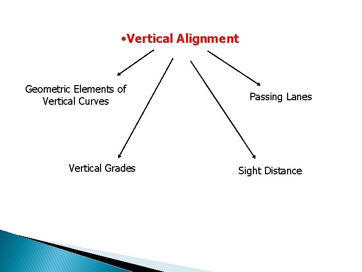
• Vertical Alignment Geometric Elements of Vertical Curves Vertical Grades Passing Lanes Sight Distance
Vertical Alignment � Highway engineers generally separate the characteristics of variations in typography according to the terrain: ◦ Level terrain: highway sight distances, as governed by both horizontal and vertical restrictions, are usually long or can be made without construction difficulty. ◦ Rolling terrain: natural slopes consistently rise above or fall below the road grade, and occasional steep slopes offer some restriction to normal alignment. ◦ Mountainous terrain: longitudinal and transverse changes in the elevation of the ground are usually abrupt, and benching and side hill excavation are frequently needed.
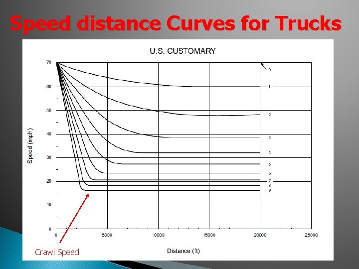
Vehicle Operational Characteristics � Passenger cars: Grades as steep as 4% to 5% generally do not affect speed of most vehicles (may affect some compact/subcompact vehicles) � Trucks: ◦ Effects on speed much more important ◦ Maximum speed on upgrade is determined length and steepness of the grade, and the truck’s weight/power ratio (gross weight/engine power)
Speed distance Curves for Trucks Crawl Speed
Operational Characteristics of Trucks � Travel time (and, therefore speed) of trucks on grades is directly related to the weight/power ratio � Trucks with same weight/power ratios have similar operating characteristics � Units are kg/k. W (metric) or lb/hp (U. S. ) � Trucks with a ratio above 200 lb/hp have acceptable operating characteristics from the standpoint of highway users � Improve performance: lower weight and/or increase power
Control Grades for Design � Maximum Grades: ◦ 5% is considered adequate for design speed of 70 mph ◦ 7% to 12% is considered acceptable for design speed of 30 mph; if more important highways 7% or 8% should be used as the max ◦ Values should fall between these extremes for other design speeds ◦ Can use 1% steeper if the upgrade length is below 500 ft ◦ Use maximum design grade very infrequently
Control Grades for Design � Minimum Grades: ◦ The minimum grade is provided for drainage purposes ◦ Typical 0. 5% to 0. 3% (for high-type pavement) ◦ Particular attention should be given to the design of storm water inlets and their spacing
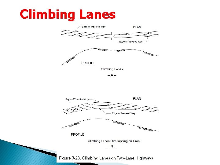
Climbing Lanes � Climbing lanes are increasingly used to decrease the amount of delay and improve safety (especially for 2 -lane highways) � There are not designated as three-lane highways, but as a two-lane highways with an added lane � Climbing lanes are designed for each direction independently of each other � Where climbing lanes are provided, there has been a high degree of compliance by drivers
Climbing Lanes
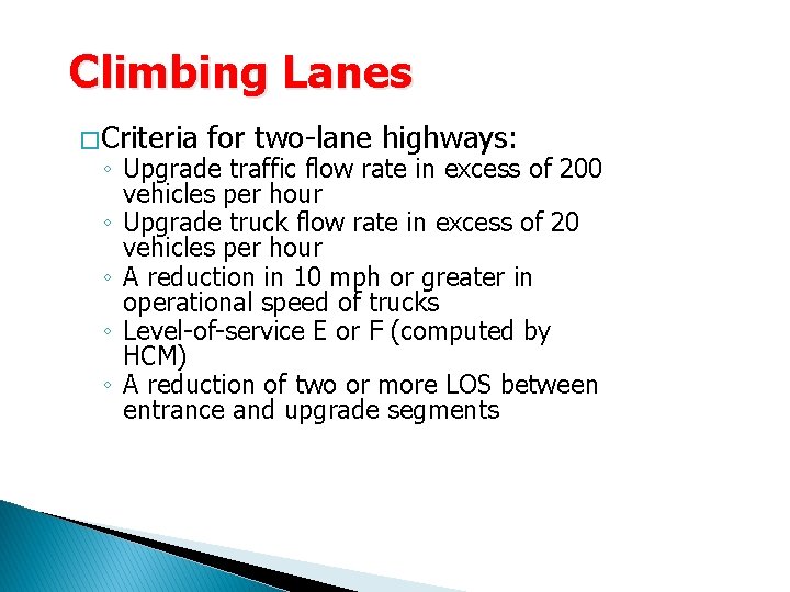
Climbing Lanes � Criteria for two-lane highways: ◦ Upgrade traffic flow rate in excess of 200 vehicles per hour ◦ Upgrade truck flow rate in excess of 20 vehicles per hour ◦ A reduction in 10 mph or greater in operational speed of trucks ◦ Level-of-service E or F (computed by HCM) ◦ A reduction of two or more LOS between entrance and upgrade segments
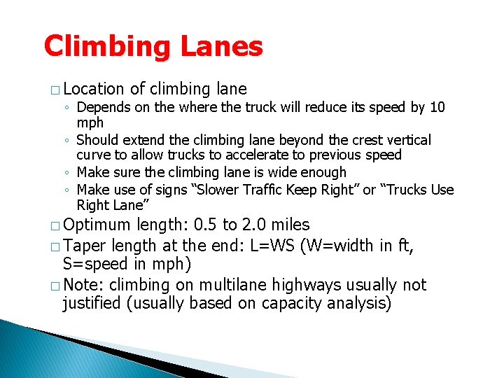
Climbing Lanes � Location of climbing lane ◦ Depends on the where the truck will reduce its speed by 10 mph ◦ Should extend the climbing lane beyond the crest vertical curve to allow trucks to accelerate to previous speed ◦ Make sure the climbing lane is wide enough ◦ Make use of signs “Slower Traffic Keep Right” or “Trucks Use Right Lane” � Optimum length: 0. 5 to 2. 0 miles � Taper length at the end: L=WS (W=width in ft, S=speed in mph) � Note: climbing on multilane highways usually not justified (usually based on capacity analysis)
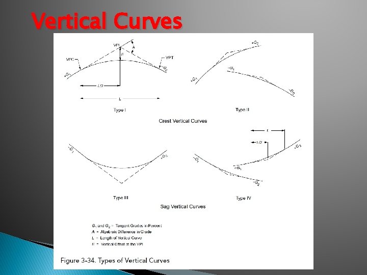
Vertical Curves � There are two types of vertical curves: ◦ Crest curves ◦ Sag curves � Design controlled by stopping sight distance � On occasion, decision sight distance may be needed � Vertical curves should result in a design that is safe, comfortable in operation, pleasing in appearance, and provide adequate drainage
Vertical Curves
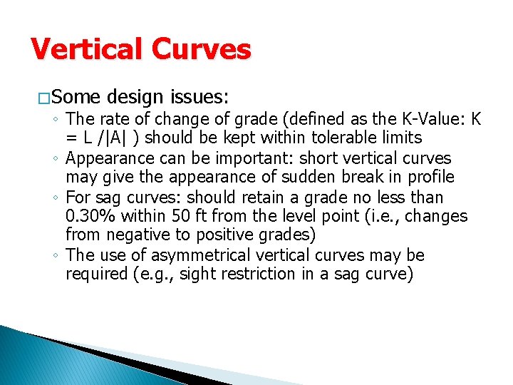
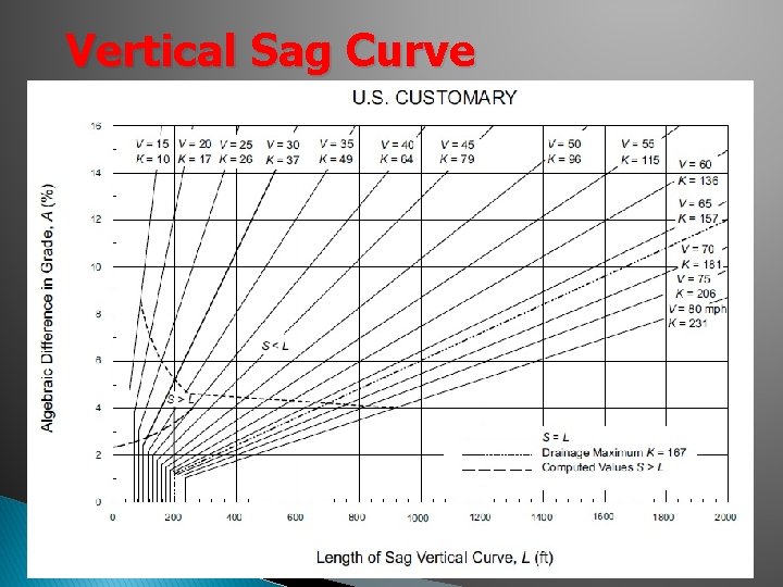
Vertical Curves � Some design issues: ◦ The rate of change of grade (defined as the K-Value: K = L /|A| ) should be kept within tolerable limits ◦ Appearance can be important: short vertical curves may give the appearance of sudden break in profile ◦ For sag curves: should retain a grade no less than 0. 30% within 50 ft from the level point (i. e. , changes from negative to positive grades) ◦ The use of asymmetrical vertical curves may be required (e. g. , sight restriction in a sag curve)
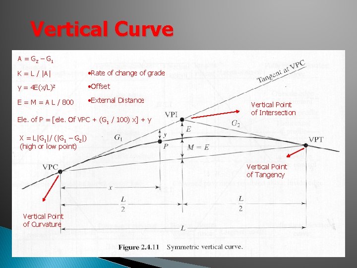
Vertical Curve A = G 2 – G 1 K = L / |A| • Rate of change of grade y = 4 E(x/L)2 • Offset E = M = A L / 800 • External Distance Ele. of P = [ele. Of VPC + (G 1 / 100) x] + y Vertical Point of Intersection X = L|G 1|/ (|G 1 – G 2|) (high or low point) Vertical Point of Tangency Vertical Point of Curvature
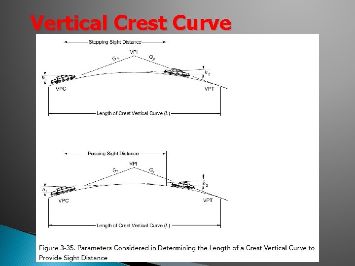
Vertical Crest Curve
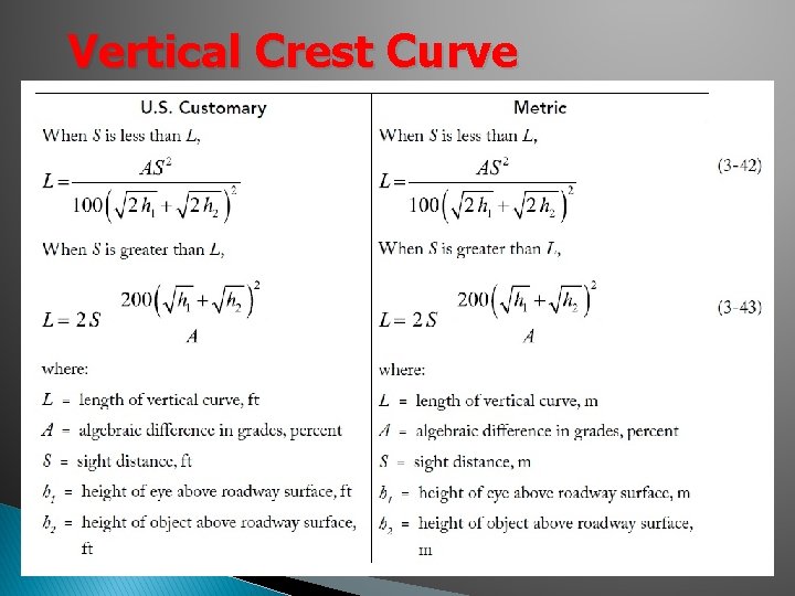
Vertical Crest Curve
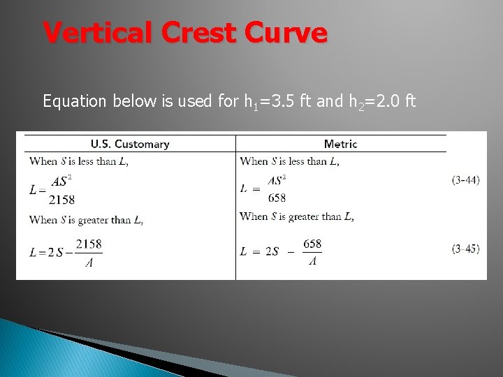
Vertical Crest Curve Equation below is used for h 1=3. 5 ft and h 2=2. 0 ft
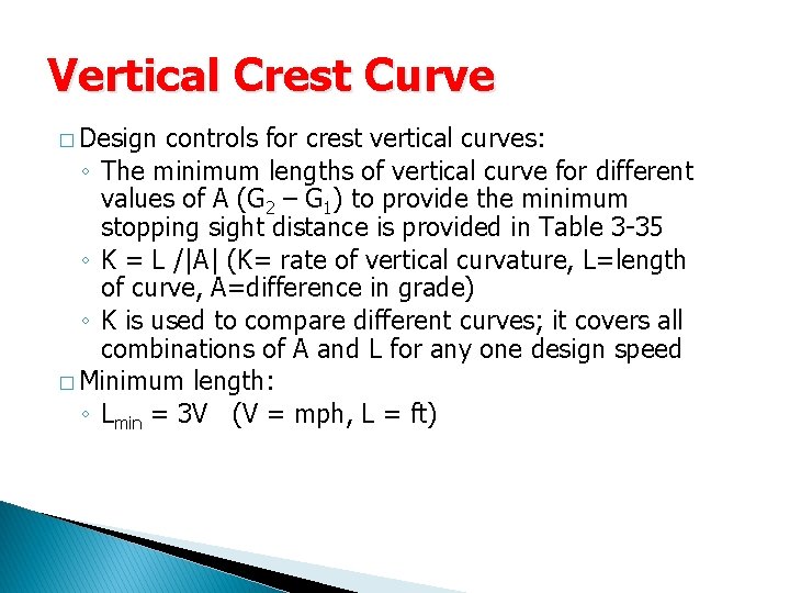
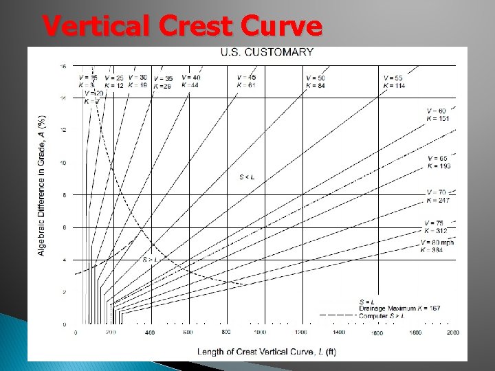
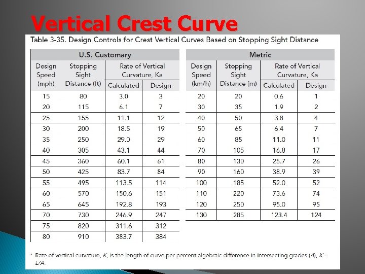
Vertical Crest Curve � Design controls for crest vertical curves: ◦ The minimum lengths of vertical curve for different values of A (G 2 – G 1) to provide the minimum stopping sight distance is provided in Table 3 -35 ◦ K = L /|A| (K= rate of vertical curvature, L=length of curve, A=difference in grade) ◦ K is used to compare different curves; it covers all combinations of A and L for any one design speed � Minimum length: ◦ Lmin = 3 V (V = mph, L = ft)
Vertical Crest Curve
Vertical Crest Curve
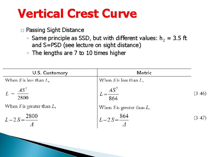
Vertical Crest Curve � Passing Sight Distance ◦ Same principle as SSD, but with different values: h 2 = 3. 5 ft and S=PSD (see lecture on sight distance) ◦ The lengths are 7 to 10 times higher
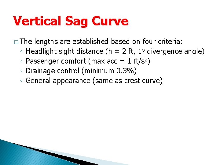
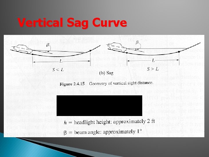
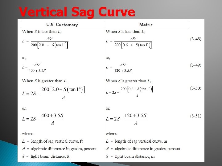
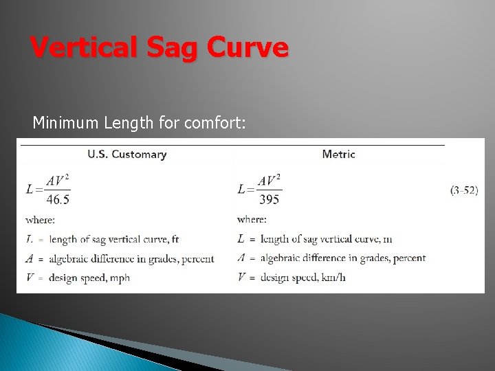
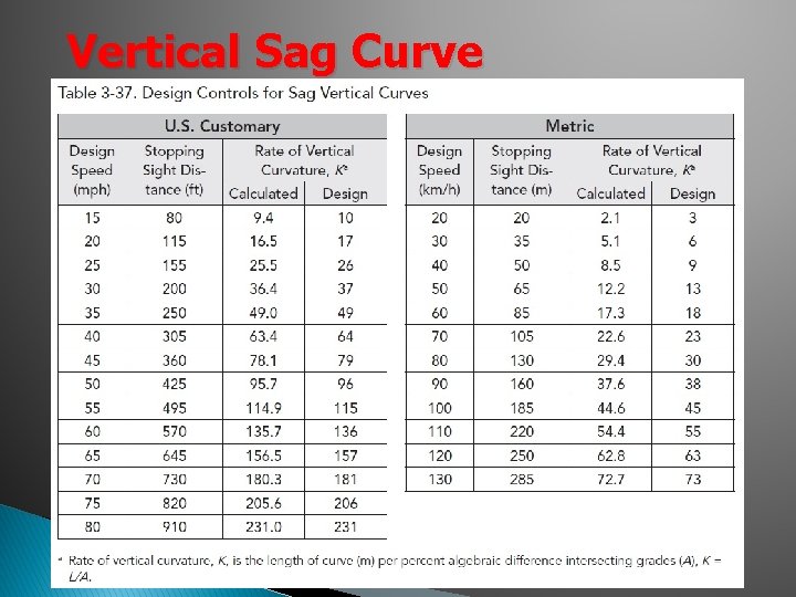
Vertical Sag Curve � The ◦ ◦ lengths are established based on four criteria: Headlight sight distance (h = 2 ft, 1 o divergence angle) Passenger comfort (max acc = 1 ft/s 2) Drainage control (minimum 0. 3%) General appearance (same as crest curve)
Vertical Sag Curve
Vertical Sag Curve
Vertical Sag Curve Minimum Length for comfort:
Vertical Sag Curve
Vertical Sag Curve
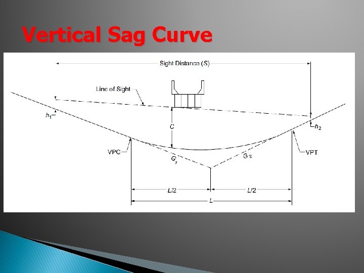
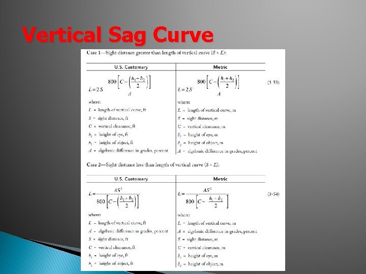
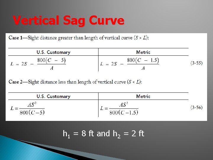
Vertical Sag Curve � Since many sag vertical curves are used at grade separated locations (overpass, bridges), highway engineers need to determine if the under passing structure creates a visibility impediment � Can use a graphical method or the equations provided in the text
Vertical Sag Curve
Vertical Sag Curve
Vertical Sag Curve h 1 = 8 ft and h 2 = 2 ft
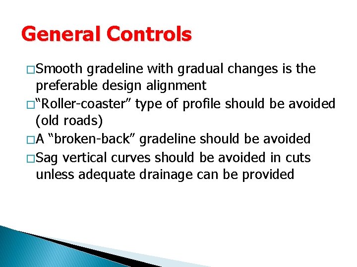
General Controls � Smooth gradeline with gradual changes is the preferable design alignment � “Roller-coaster” type of profile should be avoided (old roads) � A “broken-back” gradeline should be avoided � Sag vertical curves should be avoided in cuts unless adequate drainage can be provided
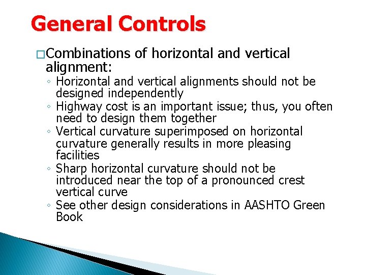
General Controls � Combinations alignment: of horizontal and vertical ◦ Horizontal and vertical alignments should not be designed independently ◦ Highway cost is an important issue; thus, you often need to design them together ◦ Vertical curvature superimposed on horizontal curvature generally results in more pleasing facilities ◦ Sharp horizontal curvature should not be introduced near the top of a pronounced crest vertical curve ◦ See other design considerations in AASHTO Green Book
Examples
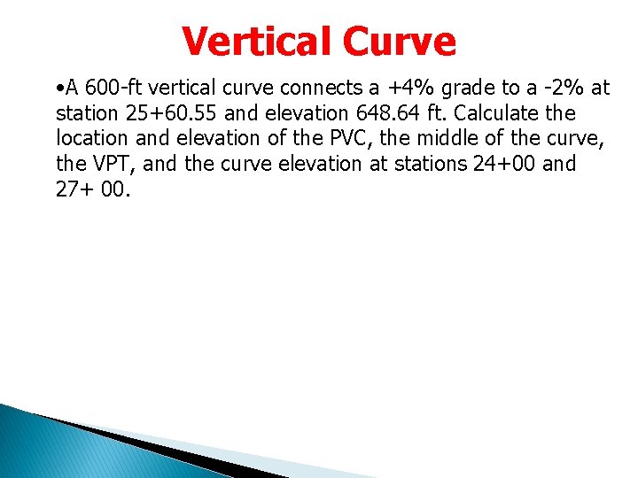
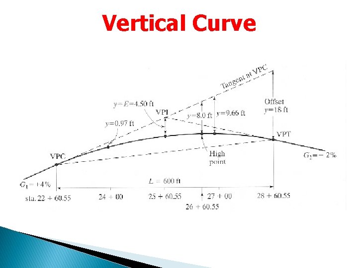
Vertical Curve • A 600 -ft vertical curve connects a +4% grade to a -2% at station 25+60. 55 and elevation 648. 64 ft. Calculate the location and elevation of the PVC, the middle of the curve, the VPT, and the curve elevation at stations 24+00 and 27+ 00.
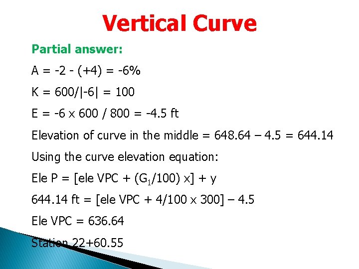
Vertical Curve Partial answer: A = -2 - (+4) = -6% K = 600/|-6| = 100 E = -6 x 600 / 800 = -4. 5 ft Elevation of curve in the middle = 648. 64 – 4. 5 = 644. 14 Using the curve elevation equation: Ele P = [ele VPC + (G 1/100) x] + y 644. 14 ft = [ele VPC + 4/100 x 300] – 4. 5 Ele VPC = 636. 64 Station 22+60. 55
Vertical Curve
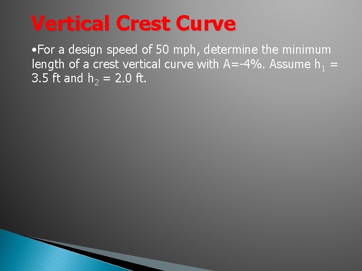
Vertical Crest Curve • For a design speed of 50 mph, determine the minimum length of a crest vertical curve with A=-4%. Assume h 1 = 3. 5 ft and h 2 = 2. 0 ft.
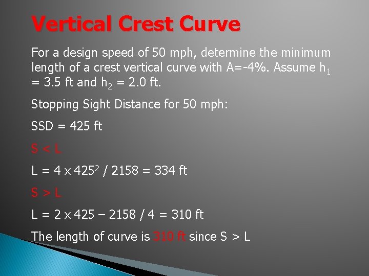
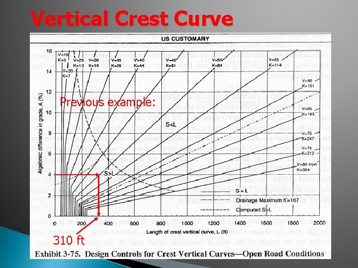
Vertical Crest Curve For a design speed of 50 mph, determine the minimum length of a crest vertical curve with A=-4%. Assume h 1 = 3. 5 ft and h 2 = 2. 0 ft. Stopping Sight Distance for 50 mph: SSD = 425 ft S<L L = 4 x 4252 / 2158 = 334 ft S>L L = 2 x 425 – 2158 / 4 = 310 ft The length of curve is 310 ft since S > L
Vertical Crest Curve Previous example: 310 ft
Vertical Sag Curve For a design speed of 60 mph, determine the length of the sag vertical curve with A = +10%
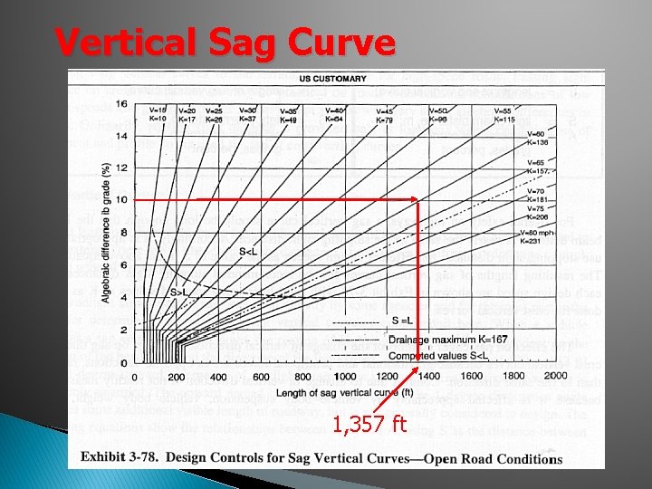
Vertical Sag Curve For a design speed of 60 mph, determine the length of the sag vertical curve with A = +10% Stopping Sight Distance: 570 ft For S < L L = 10 x 5702 / (400 + 3. 5 x 570) = 1, 357 ft Check for comfort: L = 10 x 602 / 46. 5 = 774 ft (L = 1, 357 ft is higher)
Vertical Sag Curve 1, 357 ft