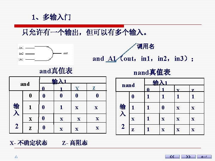
Verilog and ninput AND gate nand ninput NAND


; input")


 是一种多分支条件选择语句,一般形式如下: case (case_expr) item_expr 1: statement 1; item_expr 2: statement 2; …… default:")


- Slides: 28
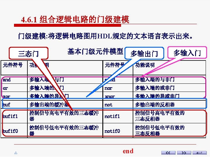
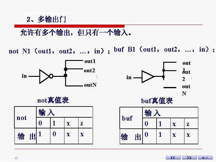
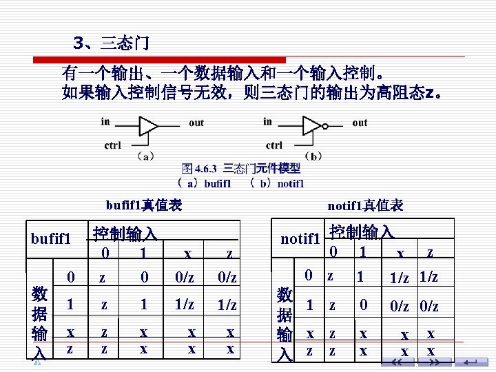
Verilog 基本门级元件 and n-input AND gate nand n-input NAND gate buf n-output buffer not n-output inverter bufif 0 tri-state buffer; Io enable or n-input OR gate nor n-input NOR gate bufif 1 tri-state buffer; hi enable xor n-input exclusive OR gate notif 0 tri-state inverter; Io enable xnor n-input exclusive NOR gate notif 1 tri-state inverter; hi enable
xor真值表 输入 1 or 0 输 入 2 0 1 X Z 0 1 X X xor 输入 1 0 1 X Z 0 0 1 X X 1 1 1 输 入 1 1 0 X X 1 X X 2 X X X Z X 1 X X Z X X
//Gate-level description of a 2 -to -4 -line decoder 4、设计举例 module _2 to 4 decoder 试用Verilog语言的门级 (A 1, A 0, E, Y); input A, B, E; 元件描述 2线-4线译码器. 说明 output [3: 0]Y; 部分 wire A 1 not, A 0 not, Enot; not n 1 (A 1 not, A 1), n 2 (A 0 not, A 0), n 3 (Enot, E); 功能 nand 描述 n 4 (Y[0], A 1 not, A 0 not, Enot), n 5 (Y[1], A 1 not, A 0, Enot), n 6 (Y[2], A 1, A 0 not, Enot), n 7 (Y[3], A 1, A 0, Enot); endmodule
例2 用Verilog的门级元件进行 描述由三态门构成的2选1数据选 择器 。 //Gate-level description of a 2 -to-1 -line multiplexer module _2 to 1 muxtri (A, B, SEL, L); input A, B, SEL output L; tri L; bufif 1 (L, B, SEL); bufif 0 (L, A, SEL); endmodule
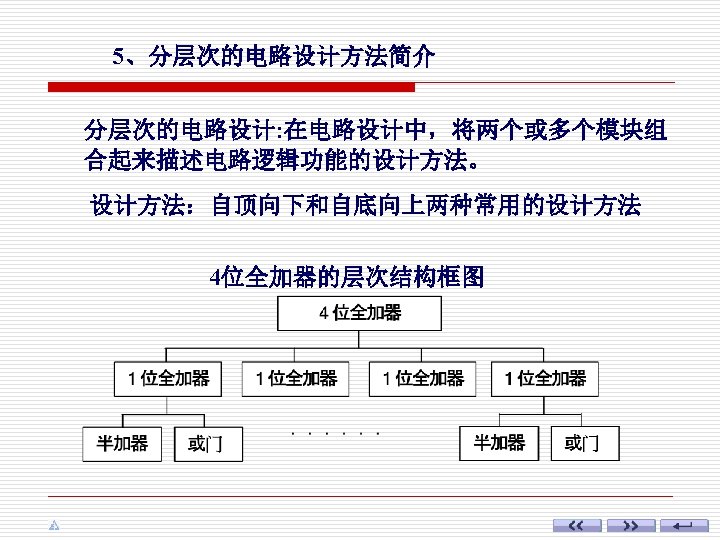
//Gate-level hierarchical description of 4 -bit adder // Description of half adder module halfadder (S, C, A, B); input A, B; output S, C; //Instantiate primitive gates xor (S, A, B); and (C, A, B); endmodule
//Description of 1 -bit full adder module fulladder (S, CO, A, B, CI); input A, B, CI; output S, CO; wire S 1, D 2; //内部节点信号 //Instantiate the halfadder HA 1 (S 1, D 1, A, B); halfadder HA 2 (S, D 2, S 1, CI); or g 1(CO, D 2, D 1); endmodule S 1 D 2
//Description of 4 -bit full adder module _4 bit_adder (S, C 3, A, B, C_1); input [3: 0] A, B; input C_1; output [3: 0] S; output C 3; wire C 0, C 1, C 2; //内部进位信号 //Instantiate the fulladder FA 0 (S[0], C 0, A[0], B[0], C_1), FA 1 (S[1], C 1, A[1], B[1], C 0), FA 2 (S[2], C 2, A[2], B[2], C 1), FA 3 (S[3], C 3, A[3], B[3], C 2); endmodule
位运算符与缩位运算的比较 A: 4’b 1010 、 B: 4’b 1111, 位运算 缩位运算 ~A = 0101 A&B= ~B = 0000 1010 &A=1& 0&1&0=0 ~&A=1 &B=1 A|B= 1111 |A=1 ~|B=0 A^B= 0101 ^A=0 ^B=0 A~^B= 1010 ~^A=1 ~^B=1
//Dataflow description of a 2 -to-4 -line decoder, module decoder_df (A 1, A 0, E, Y); input A 1, A 0, E; output [3: 0] Y; assign Y[0] = ~(~A 1 & ~A 0 & ~E); assign Y[1] = ~(~A 1 & A 0 & ~E); assign Y[2] = ~(A 1 & ~A 0 & ~E); assign Y[3] = ~(A 1 & A 0 & ~E); endmodule
用条件运算符描述了一个 2选1的数据选择器。 //Dataflow description of 2 -to-1 -line multiplexer module mux 2 x 1_df (A, B, SEL, L); input A, B, SEL; output L; assign L = SEL ? A : B; endmodule 在连续赋值语句中,如果SEL= 1,则输出L=A;否则L=B。
2、多路分支语句(case语句) 是一种多分支条件选择语句,一般形式如下: case (case_expr) item_expr 1: statement 1; item_expr 2: statement 2; …… default: default_statement; //default语句可以省略
例 //Behavioral description of 2 -to-1 -line multiplexer module mux 2 to 1_bh(A, B, SEL, L); input A, B, SEL; output L; reg L; //define register variable always @(SEL or A or B) if (SEL == 1) L = b; //也可以写成 if (SEL) L=B; else L = A; endmodule
//Behavioral description of 4 -to-1 -line multiplexer module mux 4 to 1_bh(A, SEL, E, L); input [3: 0] A; input [1: 0] SEL; output L; reg L; always @(A or SEL or E) begin if (E==1) L = 0; else case (SEL) 2’d 0: L = A[0]; 2’d 1: L = A[1]; 2’d 2: L = A[2]; 2’d 3: L = A[3]; endcase endmodule