Velocity determination Float Method Inexpensive and simple Measures


, 15 -16 July 2012 event: blue")
 2 Brasage en verre (matériau agglomérant soudé) 3 Corps de")
, the immersed pressure transducer is hanged in the")

 Logiciel (ex. Labview)")

")


 is a kind of sonar: it operates by")
")
- Slides: 29
Velocity determination: Float Method Inexpensive and simple Measures surface velocity Mean velocity obtained using a correction factor Basic idea: measure the time that it takes an object to float a specified distance downstream
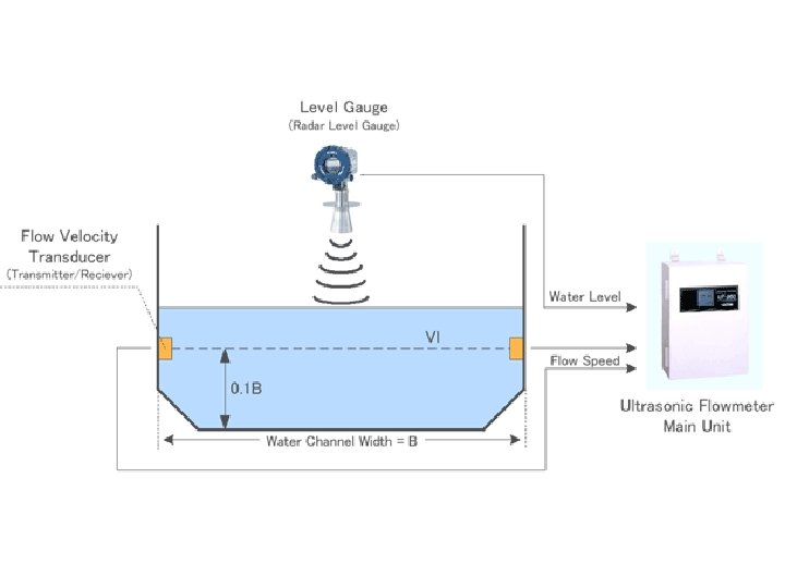
The electromagnetic sensors use the Faraday Principle to measure the water speed. As a conductor (water) moves through an electromagnetic field (produced by the sensor), it generates a voltage that is measured by the sensor electrodes.
ou GPRS
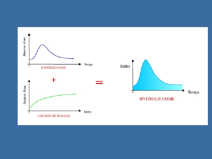
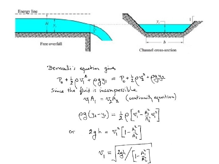
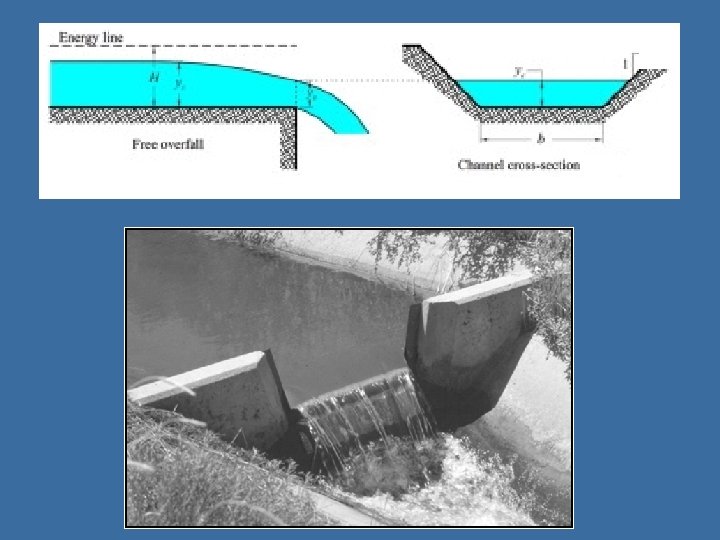
Etablissement des relations de tarage hauteurs-débits
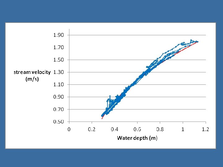
Rating curve hysteresis loop in Zenne river (Lot), 15 -16 July 2012 event: blue triangles – rising stage, green squares – falling stage
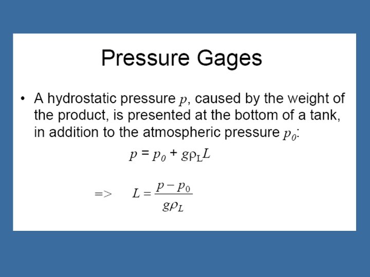
1 Membrane (formant diaphragme) 2 Brasage en verre (matériau agglomérant soudé) 3 Corps de base L'élément de mesure de ce capteur de pression est une cellule céramique capacitive sèche. Le corps de base et la membrane sont en céramique de grande pureté (Al 2 O 3 99. 9 % )
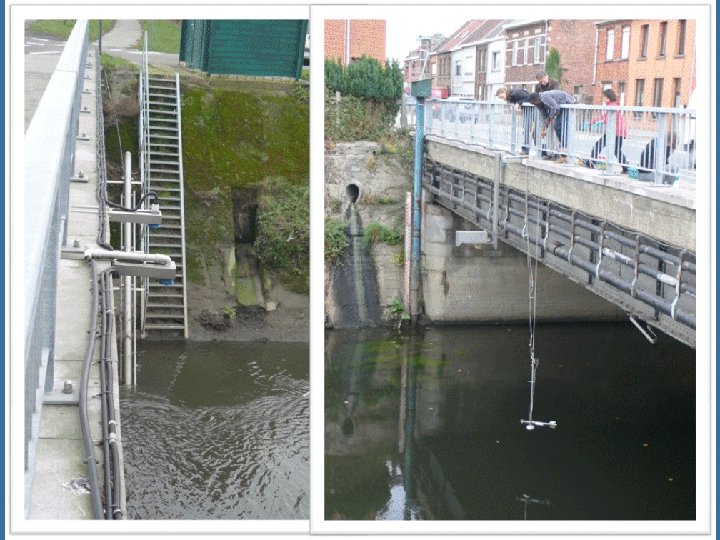
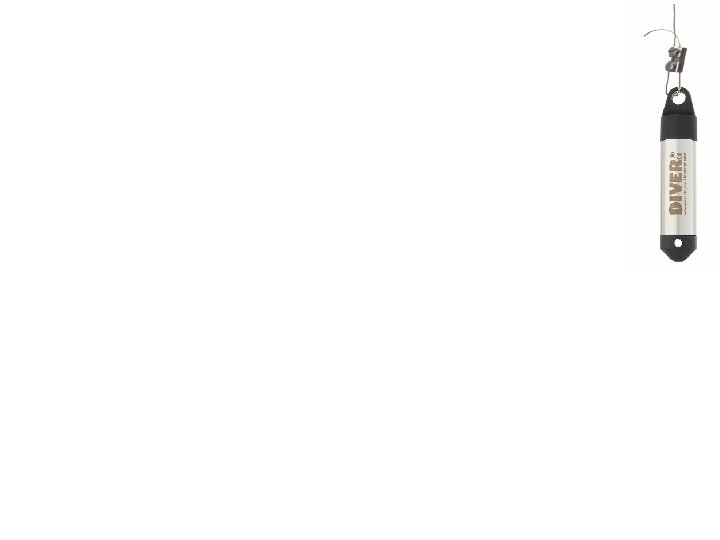
In the illustrated configuration (rio Parapeti), the immersed pressure transducer is hanged in the internal part of a (perforated) protection tube. 12
Principe du limnimètre bulle-à-bulle
La chaîne de mesures Phénomène physique Capteur Conditionneur Instrument (carte d’acquisition) Logiciel (ex. Labview)
méthode d’injection de traceur à débit constant q et concentration C 1
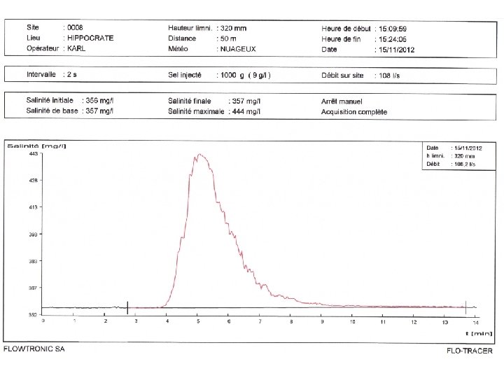
méthode par intégration (injection instantanée)
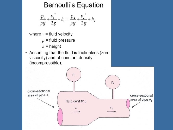
Tube de Pitot Il est constitué de deux tubes coudés concentriques dont les orifices, en communication avec le fluide dont on veut mesurer la vitesse, sont disposés de façon particulière. • L'un, placé orthogonalement, a une vitesse relative v égale à la vitesse du fluide et une pression statique ps égale à la pression ambiante. • L'autre, placé dans le sens de l'écoulement, a une vitesse relative nulle et une pression totale pt, somme de la pression dynamique et de la pression statique. La différence entre ces pressions donne la vitesse v = vitesse p = pression dans la conduite (ps est la pression statique, pt est la pression totale) ρ = masse volumique du fluide
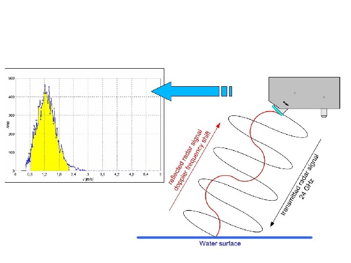
The radar flow-meter is also based on the principle of the frequency shift due to the Doppler effect. The radar sensor is installed pointing in a defined angle on the water surface. Via the sending antenna, a constant frequency of 24 GHz is emitted. This signal is partly reflected at the water surface (minimum 3 mm waves) and returns with a specific frequency shift to the receiving antenna. With support of spectral analysis, filters and statistical methods, the surface velocity is obtained. Significant progress has been reached recently in these data processing techniques, improving the applicability of this non-intrusive measurement method.
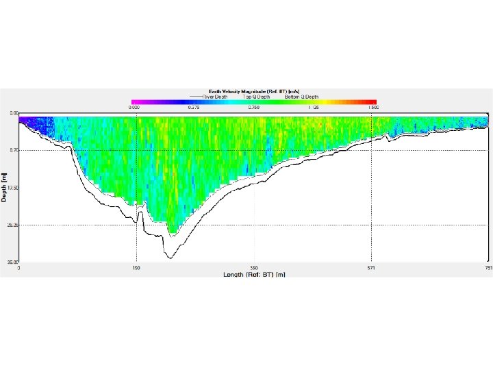
The Acoustic Doppler Current Profiler (ADCP) is a kind of sonar: it operates by transmitting acoustic pulses into the water column. These acoustic pulses propagate through the water column and are “reflected” by suspended particles which are carried by water currents. The reflected signals (echoes) are received by the ADCP. Echoes arriving later, from deeper in the water column, are assigned greater depths in the velocity profile. This allows the ADCP to form vertical profiles of current velocity. Particles within the current flow moving towards the instrument exhibit higher frequencies while those moving away exhibit lower frequencies. This is the well-known Doppler shift, which enables precise measurement of current speed and direction, allowing to reconstitute the full velocity field.
side-looking ADCP (around 15 k. Euros HTVA)