Vehicle Lateral Stability Using Active Suspension Introduction Lateral

Vehicle Lateral Stability Using Active Suspension

Introduction Lateral stability in vehicles depends on the ability to corner at speeds without skid in the lateral direction.

Lateral motion stability is achieved by an intelligent combination of actuators which control the following parameters at each wheel independently: § Suspension forces § Braking forces § Engine torques.

Aim of the project In this presentation, we develop a model for suspension design to optimize between ride comfort and lateral performance. Cornering performance of the vehicle is limited by the normal load available to the inner wheel

Role of Suspension systems play an important role in the following parameters Ø Weight distribution Ø Roll of the vehicle Ø Ride quality Ø Pitch of the vehicle Ø Manoeuvrability

Ø In traditional suspension systems, it becomes increasingly complicated to manoeuvre the car at higher speeds. Ø This is because the various parameters such as the weight distribution, roll rate and pitch rate are at unfavourable values.

Car CAD Model
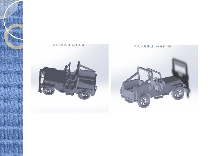

Suspension CAD Model Side view Isometric view

Traditional Suspension Systems Traditional suspension systems consist of a spring-damper system. It is explained as follows :

Quarter Car Model �The quarter car model is a model that models the motion of a single suspension system.

Governing Equations

�Damping will have an effect on the amplitudes of motion even though it does not have a significant effect on the natural frequencies. �A convenient way to solve for the amplitudes is to use a complex number approach (assume z = |Z|eiωt).

Active Suspensions Next generation evolution of suspension design Ø Depending on the control algorithms, the forces, damping coefficients can be varied conveniently to suit the ride and performance. Ø

Working Magnetorheological fluid Magnetorheological Suspension Assembly

Principle behind Ø When a magnetic field is applied between the two ends, there is an increase in the viscosity of the MR fluid. Ø Due to this, there is a variation in the damping coefficient. Ø Thus, a calculated magnetic field can be applied for a required change in the damping coefficient.

Schematic diagram of the system

Implementation in Simulink

Controller design

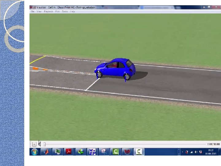
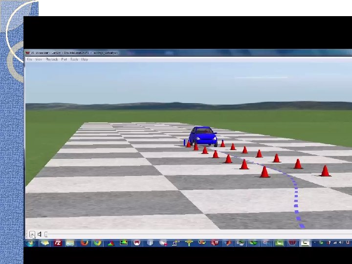
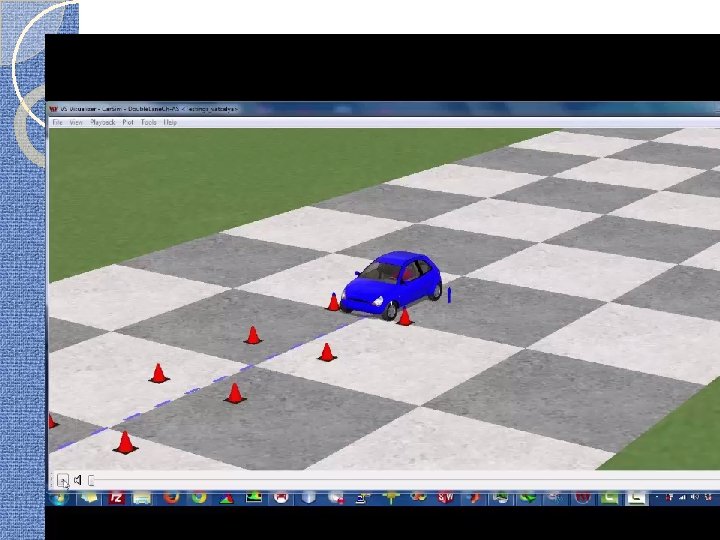
�The various gains associated can be seen in consecutive steps in the simulink model �The Simulink model was imported to Carsim. �The model was implemented and its performance was compared with a car lacking active suspension.

Car. Sim Implementation �Car parameters Sprung mass=750 kg Unsprung Mass=90 kg Track width=1. 78 m Wheelbase=2. 3 m Spring stiffness 153 k. N/m – front 82 k. N/m - rear 75 k. W front-wheel drive 4 -speed gearbox Front and rear independent suspension.

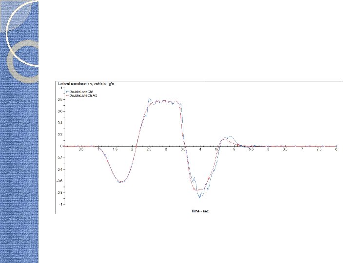
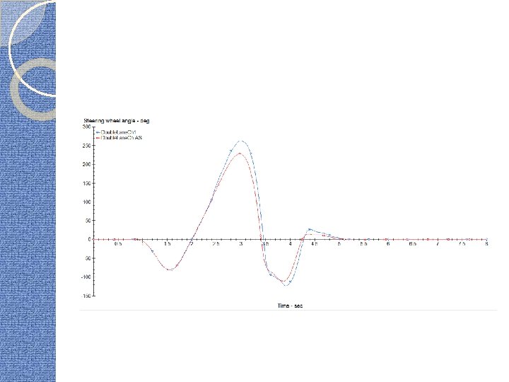
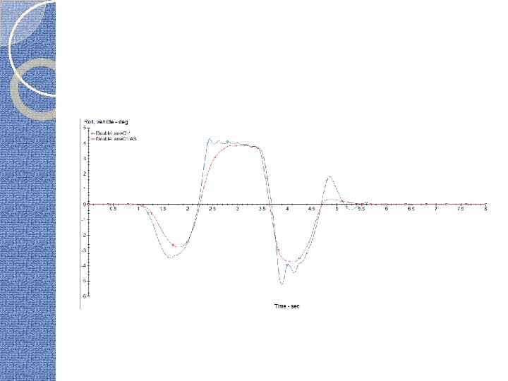
Important plots The active suspension model reduces roll considerably

Vertical force – measure of passenger comfort

Active suspension reduces the pitch

References Jorge de-J Lozoya-Santos, Ruben Morales-Menendez and Ricardo A Ramirez-Mendoza. Evaluation of on–off semiactive vehicle suspension systems by using the hardware-inthe-loop approach and the software-in-the-loop approach � V. Drobnya, M. Valasek. Vehicle Lateral Dynamics Stabilization Using Active Suspension � Zhu R and Niu L. Research on co-simulation and test of semi -active suspension. In: 2 nd international conference on computer modelling and simulation, Sanya, Hainan, People’s Republic of China, 22– 24 January 2010, pp. 353– 357. New York: IEEE. � Ramli R. Dynamic simulation of semi-active suspension systems for durability analysis. Ph. D Thesis, University of Leeds, UK, 2007. � Mechanical Simulation Corporation. Car. Sim mechanical simulation references and help files. � Mat. Lab Help Files �
- Slides: 31