VARIOUS CLOUD PATTERNS NINE TYPE SIX TYPE COMMA


 V O v u X 5")


- Slides: 31
VARIOUS CLOUD PATTERNS NINE TYPE SIX TYPE COMMA TYPE EYE TYPE 2
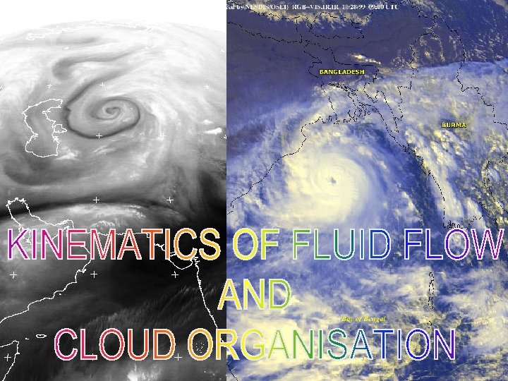
KINEMATICS • Kinematics of fluid flow refers to the description of motion of the fluid without reference to the forces that are responsible for such motion. • Kinematics comes from the greek word meaning "motion". • By kinematics we mean a description of motion of a particular field without regard to how it come about or how it will evolve. • Complete solutions to specific flow problems cannot be obtained from kinematics alone, but a number of important results may be derived & applied. • Kinematics involves two fields - scalar fields such as pressure, density etc &- vector field such as wind.
KINEMATICS • Applications of kinematics of fluid flow in meteorology is to understand the organisation of clouds. • Cloud systems gets organised into various patterns like comma, bands, streets, spirals etc. nised loud atures translate h • without loosing their organised pattern. 4
WIND Y P(x, y) V O v u X 5
DECOMPOSITION OF A LINEAR WIND FIELD • 6
• equations in u and v reduces to: - 8
9
WIND FIELD TRANSLATION = u 0, v 0 VERGENCE VORTICITY DEFORMATION D 1 DEFORMATION D 2 10
I II IV • Term I represents uniform translation of air parcel. • Term II represents expansion ( >0) or contraction ( < 0) about origin. • Term III represents counterclockwise ( >0)or clockwise ( < 0) rotation about the origin. • Term IV represents deformation, the changing shape of the fluid element about the origin.
PURE TRANSLATION =0 =0 D 1, D 2 = 0 13
DIVERGENCE/CONVERG ENCE u 0=0, v 0=0, = 0 and D 1, D 2 = 0 >0 <0 14
VERGENCE AND VERTICAL MOTION 15
VORTICITY u 0=0, v 0=0, = 0 AND D 1, D 2 = 0 >0 C <0 A 16
ROLE OF WIND FIELD IN CLOUD ORGANISATION • The cloud configuration is best related to the relative wind field. • Divergence/convergence is related to vertical motion of clouds and its areal coverage. • Vorticity & deformation is related to the configuration of cloud organisation 17
What are Relative winds? Relative winds are found by subtracting the velocity (direction and speed of movement) of the system from the measured winds. 18
WIND FIELD AND RELATIVE MOTION WIND MAXIMUM E MOIST DRY Distortion of a line EE due to rotation: (a) At t=0 (thin line) and t=1 ; E (b) ) At t=2
WIND FIELD AND RELATIVE MOTION Fig : As In Previous Fig but also with translation: (a) Adding vector V to simulate the motion (b) Resultant winds on two diameters only (c ) Flow due to rotation and translation. D is the centre of synoptic winds. C is the centre of rotation. In practice the winds are recorded as in (c. ) and the speed of the system is subtracted to get relative winds 20
SIMPLE DEFORMATION ZONE IN STATIONARY SYSTEM H L H • The solid contours are streamlines and the line segment represent wind vectors • The velocity pattern is a cellular combination of vorticity centres with deformation zones between them L H L
DEFORMATION ZONE IN MOVING SYSTEM N X TRAILING X LEADING N D D N X • The total wind vectors do not reveal the deformation zones. • Deformation zones can still be located in the vorticity field. • The wind speeds can be high or low at the deformation zones. • Subtracting the system velocity will in a return to the previous figure.
COMMA CLOUD AND DEFORMATION ZONES D 2 J 1 D 1 Shaded area represents clouds • Relative streamlines for an intensifying depression moving slowly northeast D 1 – Low level deformation zone D 2 – High level deformation zone
RELATIVE WINDS & CLOUD ORGANISATION 24
25
26
27
28
29
30
31