
Vacuum systems of the NICA A Smirnov MAC
- Slides: 26
Vacuum systems of the NICA A. Smirnov MAC, Dubna 22/05/2017 1
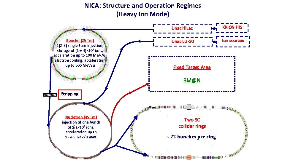
NICA: Structure and Operation Regimes (Heavy Ion Mode) Booster (25 Tm) 1(2 -3) single-turn injection, storage of (2 4)× 109 ions, acceleration up to 100 Me. V/u, electron cooling, acceleration up to 600 Me. V/u Linac HILac KRION HIS Linac LU-20 Ion sources Fixed Target Area BM@N Stripping Nuclotron (45 Tm) injection of one bunch of 2× 10⁹ ions, acceleration up to 1 - 4. 5 Ge. V/u max. Two SC collider rings ~ 22 bunches per ring
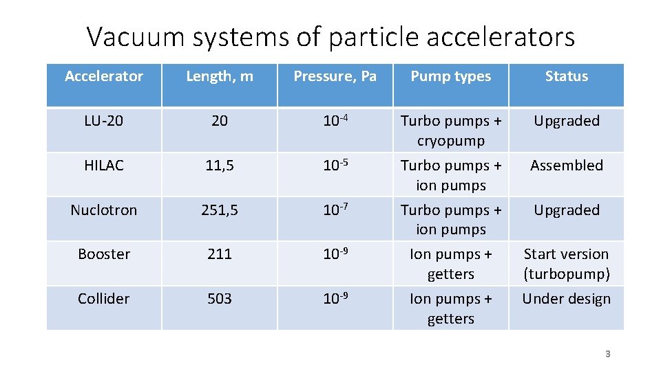
Vacuum systems of particle accelerators Accelerator Length, m Pressure, Pa Pump types Status LU-20 20 10 -4 Turbo pumps + cryopump Upgraded HILAC 11, 5 10 -5 Turbo pumps + ion pumps Assembled Nuclotron 251, 5 10 -7 Upgraded Booster 211 10 -9 Turbo pumps + ion pumps Ion pumps + getters Collider 503 10 -9 Ion pumps + getters Start version (turbopump) Under design 3
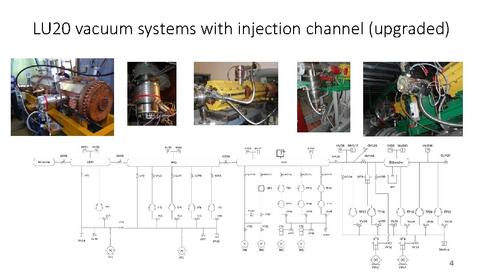
LU 20 vacuum systems with injection channel (upgraded) 4
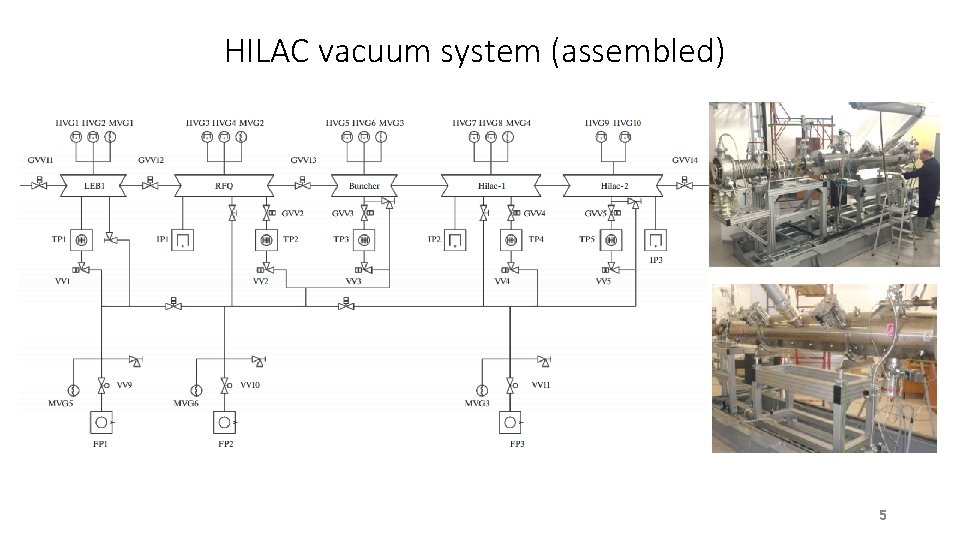
HILAC vacuum system (assembled) 5
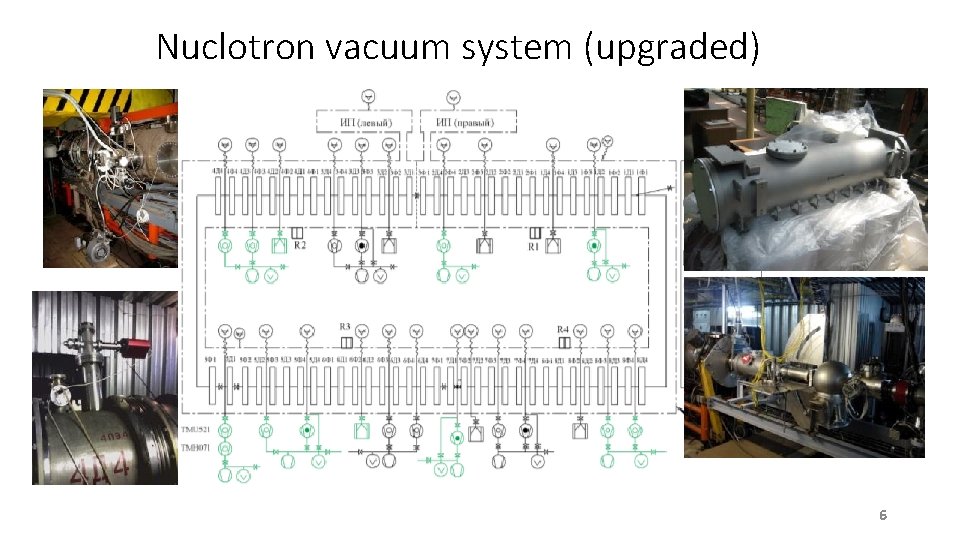
Nuclotron vacuum system (upgraded) 6
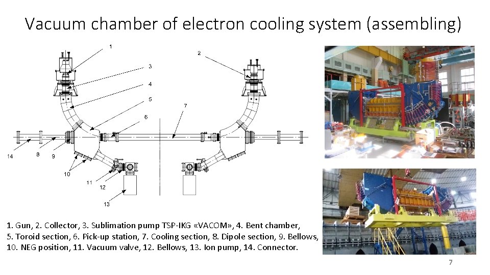
Vacuum chamber of electron cooling system (assembling) 1. Gun, 2. Collector, 3. Sublimation pump TSP-IKG «VACOM» , 4. Bent chamber, 5. Toroid section, 6. Pick-up station, 7. Cooling section, 8. Dipole section, 9. Bellows, 10. NEG position, 11. Vacuum valve, 12. Bellows, 13. Ion pump, 14. Connector. 7
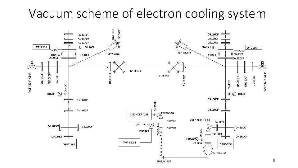
Vacuum scheme of electron cooling system 8
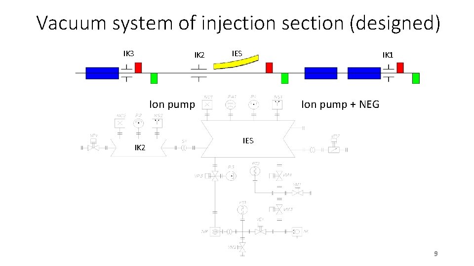
Vacuum system of injection section (designed) IK 3 IK 2 IES IK 1 Ion pump IK 2 Ion pump + NEG IES 9
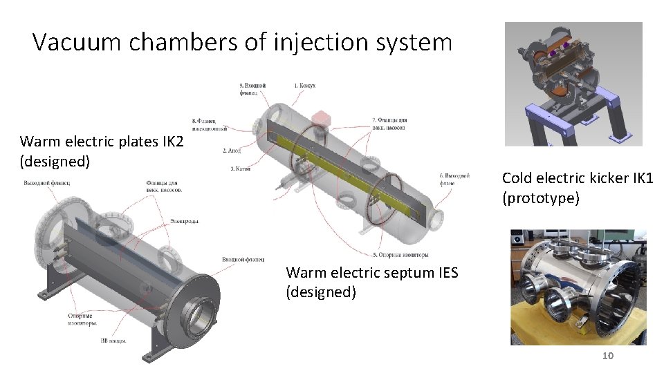
Vacuum chambers of injection system Warm electric plates IK 2 (designed) Cold electric kicker IK 1 (prototype) Warm electric septum IES (designed) 10
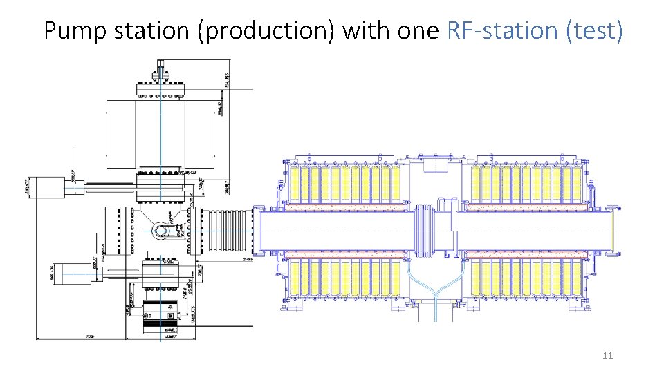
Pump station (production) with one RF-station (test) 11
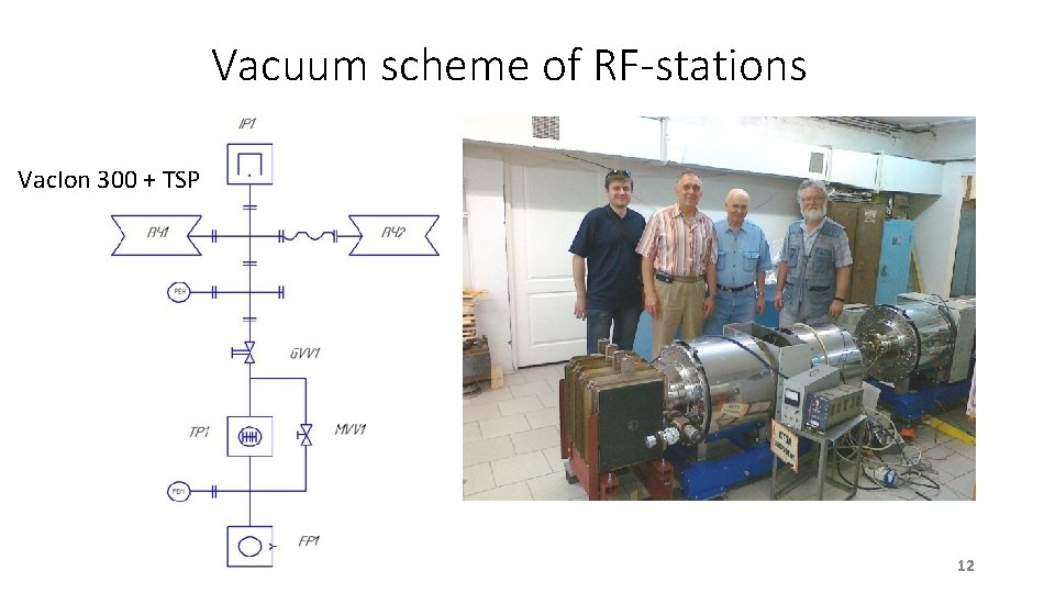
Vacuum scheme of RF-stations Vac. Ion 300 + TSP 12
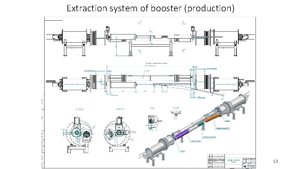
Extraction system of booster (production) 13
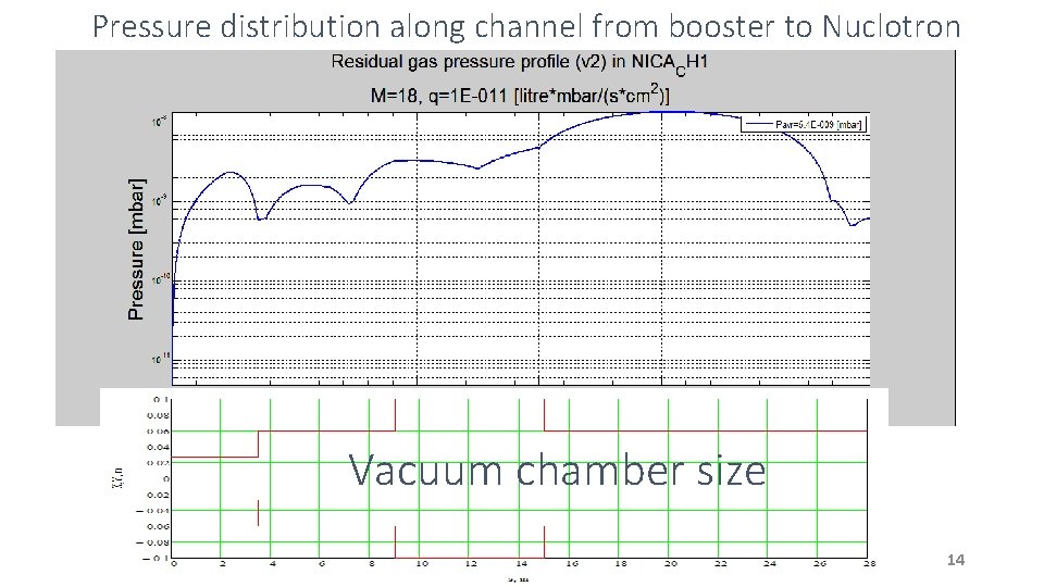
Pressure distribution along channel from booster to Nuclotron Vacuum chamber size 14
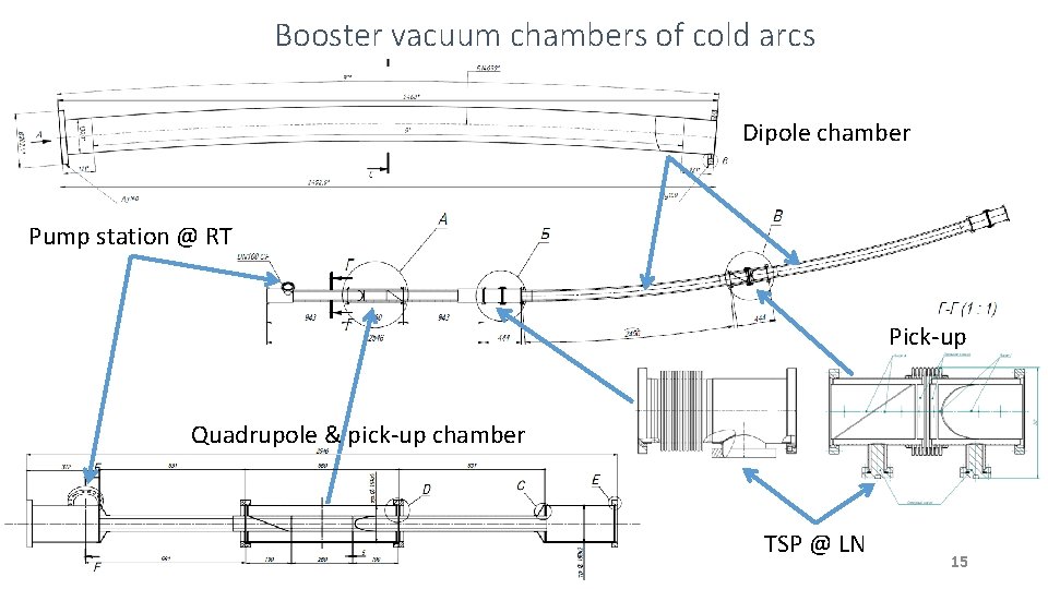
Booster vacuum chambers of cold arcs Dipole chamber Pump station @ RT Pick-up Quadrupole & pick-up chamber TSP @ LN 15
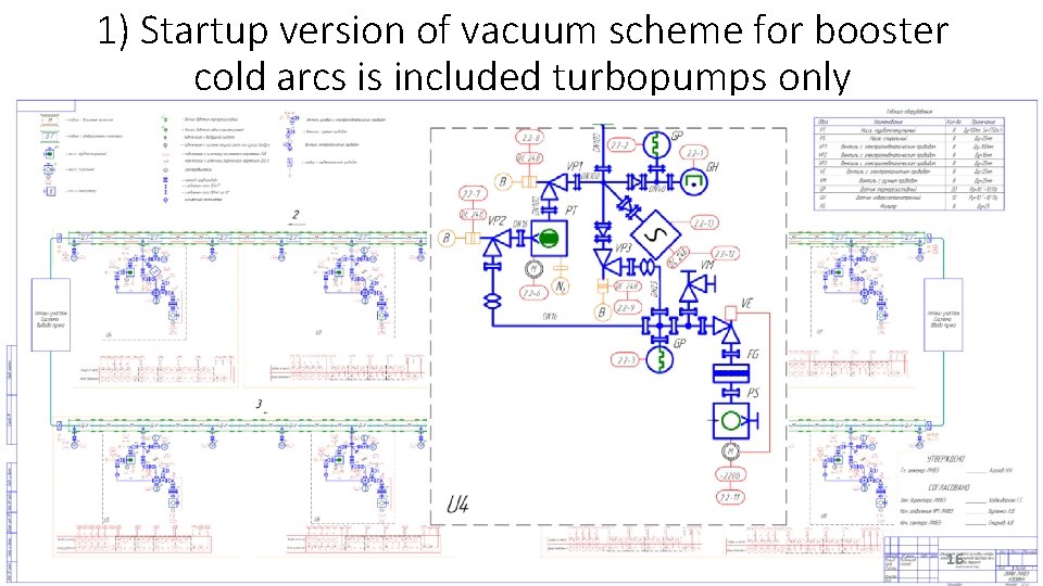
1) Startup version of vacuum scheme for booster cold arcs is included turbopumps only 16
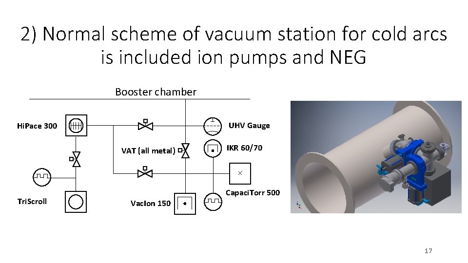
2) Normal scheme of vacuum station for cold arcs is included ion pumps and NEG Booster chamber UHV Gauge Hi. Pace 300 VAT (all metal) Tri. Scroll IKR 60/70 Capaci. Torr 500 Vac. Ion 150 17
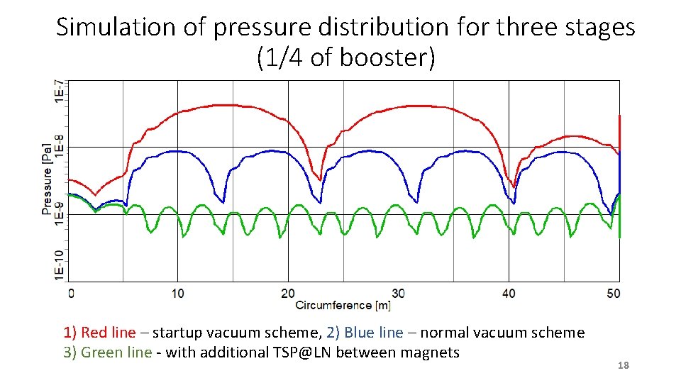
Simulation of pressure distribution for three stages (1/4 of booster) 1) Red line – startup vacuum scheme, 2) Blue line – normal vacuum scheme 3) Green line - with additional TSP@LN between magnets 18
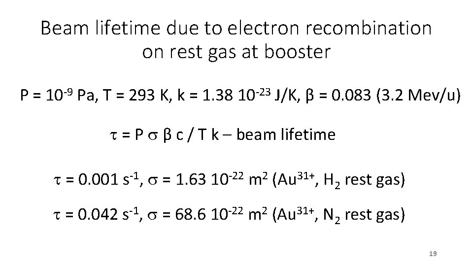
Beam lifetime due to electron recombination on rest gas at booster P = 10 -9 Pa, T = 293 K, k = 1. 38 10 -23 J/K, β = 0. 083 (3. 2 Mev/u) = P β c / T k – beam lifetime = 0. 001 s-1, = 1. 63 10 -22 m 2 (Au 31+, H 2 rest gas) = 0. 042 s-1, = 68. 6 10 -22 m 2 (Au 31+, N 2 rest gas) 19
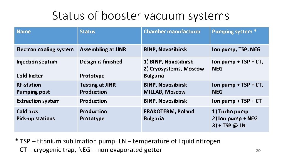
Status of booster vacuum systems Name Status Chamber manufacturer Pumping system * Electron cooling system Assembling at JINR BINP, Novosibirsk Ion pump, TSP, NEG Injection septum Design is finished Cold kicker Prototype 1) BINP, Novosibirsk 2) Cryosystems, Moscow Bulgaria Ion pump + TSP + CT, NEG RF-station Pumping post Testing at JINR Production BINP, Novosibirsk MILLAB, Moscow Ion pump + TSP + CT, NEG Extraction system Production BINP, Novosibirsk Ion pump + TSP + CT Cold arcs Pick-up stations Production Prototype FRAKOTERM, Poland Bulgaria 1) Turbo pump 2) Ion pump + NEG 3) + TSP @ LN * TSP – titanium sublimation pump, LN – temperature of liquid nitrogen CT – cryogenic trap, NEG – non evaporated getter 20
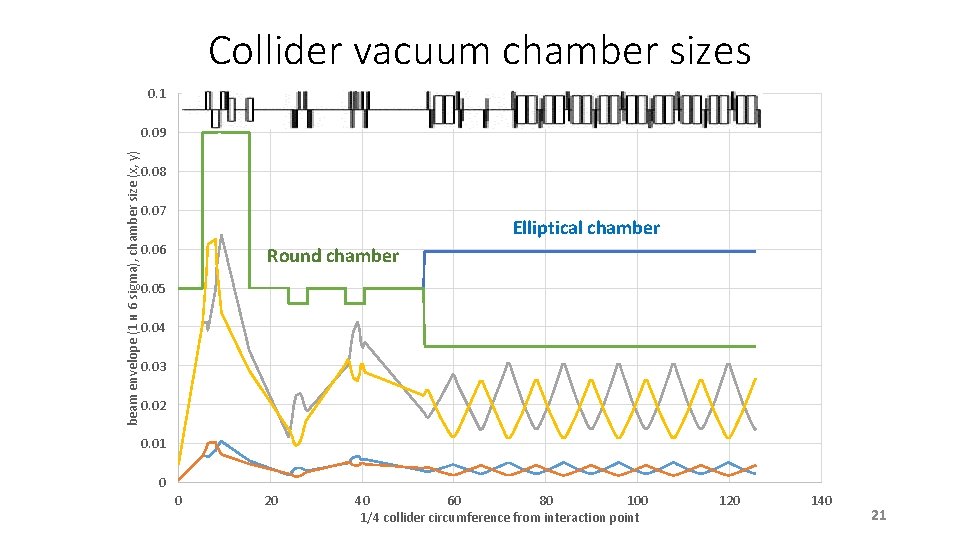
Collider vacuum chamber sizes 0. 1 beam envelope (1 и 6 sigma), chamber size (x, y) 0. 09 0. 08 0. 07 Elliptical chamber 0. 06 Round chamber 0. 05 0. 04 0. 03 0. 02 0. 01 0 0 20 40 60 80 100 1/4 collider circumference from interaction point 120 140 21
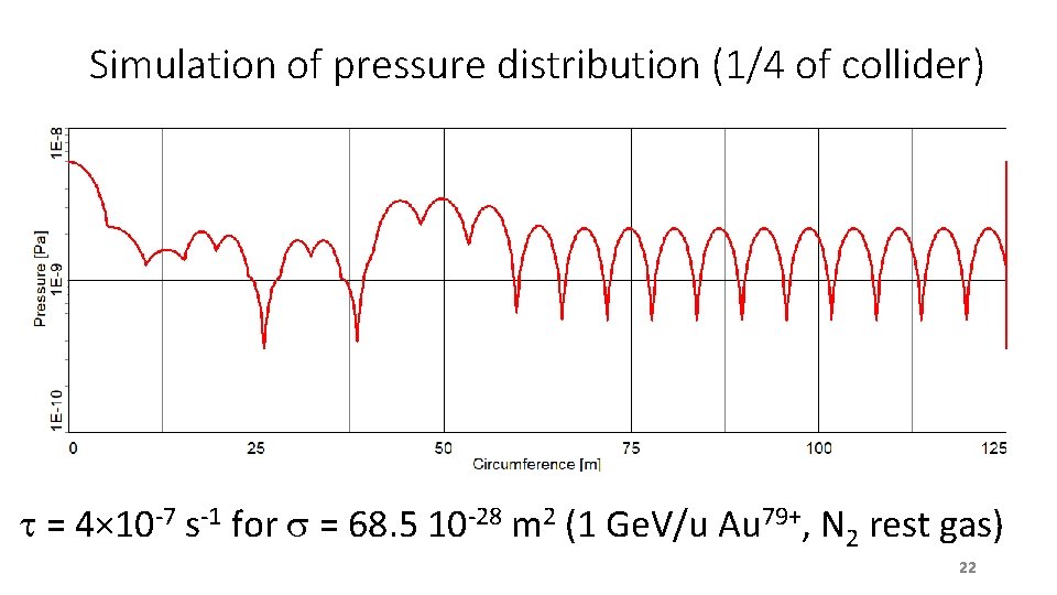
Simulation of pressure distribution (1/4 of collider) = 4× 10 -7 s-1 for = 68. 5 10 -28 m 2 (1 Ge. V/u Au 79+, N 2 rest gas) 22
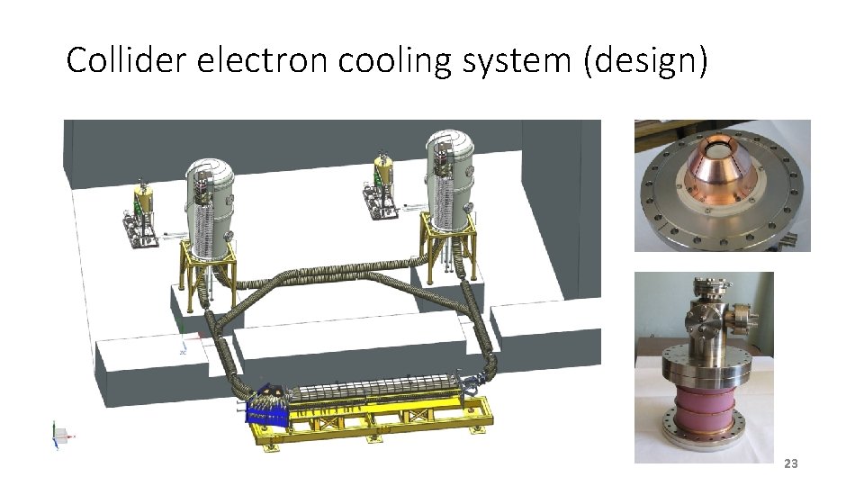
Collider electron cooling system (design) 23
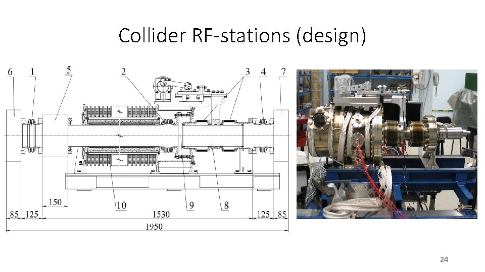
Collider RF-stations (design) 24
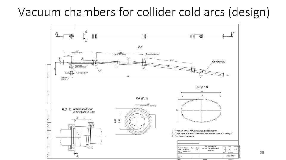
Vacuum chambers for collider cold arcs (design) 25
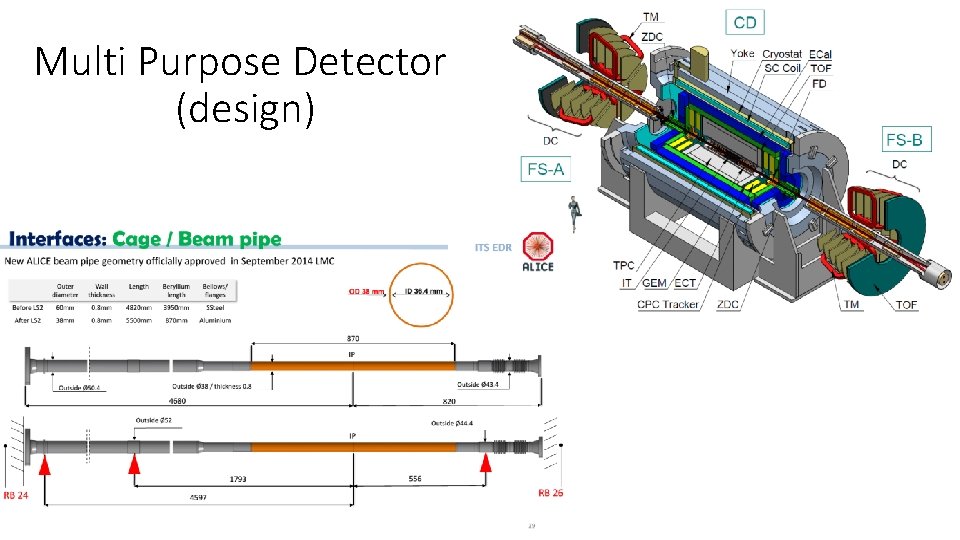
Multi Purpose Detector (design)