Vacancy type point defect Selfinterstitial type point defect


 自我插入型點缺陷(Self-interstitial type point defect)")

 Basic Assumptions of the System a). The heat transfer process for an")
 Fluid Governing Equations Continuity equation: Momentum equations: (1) (2) (3)")
 Boundary conditions of fluid a). The inlet gas flow velocity of the")
 Equations Governing Temperature Distribution For the solid components of system (4) For")
 Boundary conditions of the system’s temperature distribution a). The temperature at the")
 Defect equation (10) (11)")
 Boundary conditions of the concentration a). The concentrations at the crystal-melt interface")

 Axial temperature distributions of the crystal Length(cm) 70 Temperature (K) 60 Without")
 Axial temperature gradient of the crystal-melt interface Without heat shield With Type")
 Simulation results for OISF-ring position in crystal Length(cm) 70 Length(cm) Type A")
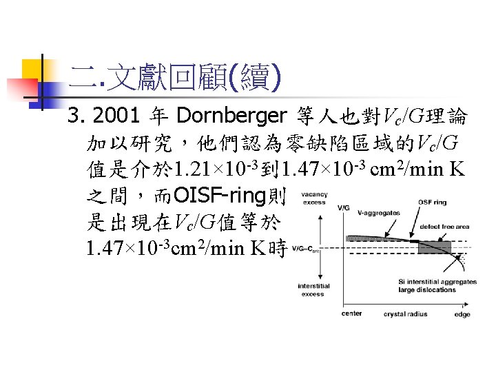
 Vc /G ratios for different heat shields Vacancy Rich Vc/G= 1. 34×")
 Flow velocity of argon gas passing through the melt-gas interface Without heat")
 New heat shield design Type C 120 degrees 140 degrees")
 Temperature distribution and argon gas flow velocity vector in the furnace Type")
 Axial temperature gradient of the crystal-melt interface With Type A heat shield")
 Velocity of argon gas flow passing through melt-gas interface Without heat shield")
 Simulation results of the OISF-ring positions in the crystal Length(cm) 70 Type")
 Vc /G ratios for the Type C heat shield Vacancy Rich Vc/G=")


- Slides: 35
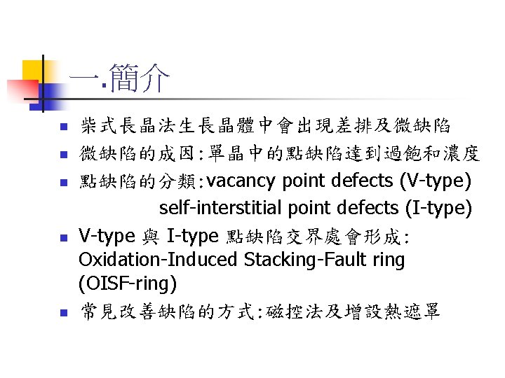
點缺陷型態示意圖 空缺型點缺陷(Vacancy type point defect) 自我插入型點缺陷(Self-interstitial type point defect)
axisymmetry 三. 數值模型 Crystal Physical model: Purge Ring Crucible Graphite Heater Melt Furnace
三. 數值模型(續) Basic Assumptions of the System a). The heat transfer process for an axisymmetric system done in a quasi-steady state condition. b). The fluid field is a two-dimensional incompressible Newtonian flow. c). An efficient heat transfer coefficient Keff is used to simplify the conditions of silicon melt flow in the melting crucible.
三. 數值模型(續) Fluid Governing Equations Continuity equation: Momentum equations: (1) (2) (3)
三. 數值模型(續) Boundary conditions of fluid a). The inlet gas flow velocity of the furnace is Vin=0. 202 m/s. b). The outlet gas pressure of the furnace is at a constant atmosphere pressure. c). The solid surfaces of the furnace have no-slip boundary conditions.
三. 數值模型(續) Equations Governing Temperature Distribution For the solid components of system (4) For the convection effect of argon gas (5) For the silicon crystal (6) For the silicon melt (7)
三. 數值模型(續) Boundary conditions of the system’s temperature distribution a). The temperature at the inlet gas is Tin=300 K. b). The temperature at the crystal-melt interface is the melting point Tmelting=1685 K. c). The gas-melt interface radiation equation is (8) d). The crystal surface radiation equation is (9) e). The wall of furnace is heat insulated.
三. 數值模型(續) Defect equation (10) (11)
三. 數值模型(續) Boundary conditions of the concentration a). The concentrations at the crystal-melt interface are assumed to be CIeq(Tm) and Cveq (Tm). b). The system is axisymmetric, i. e. c). The point defect flux at the crystal surface is zero, on the side surface of the crystal, on the top surface of the crystal,
四. 模擬結果 Temperature distributions and argon gas flow velocity vectors in the furnace
四. 模擬結果(續) Axial temperature distributions of the crystal Length(cm) 70 Temperature (K) 60 Without heat shield With Type A heat shield With Type B heat shield 50 40 1420 K 30 1170 K 20 10 (× 10 cm) 5 10 0 Radius (cm) 0 (a) without heat shield (b) Type A heat shield 5 10 Radius (cm) 0 5 10 Radius (cm) (c) Type B heat shield
四. 模擬結果(續) Axial temperature gradient of the crystal-melt interface Without heat shield With Type A heat shield With Type B heat shield Radius (× 10 cm)
四. 模擬結果(續) Simulation results for OISF-ring position in crystal Length(cm) 70 Length(cm) Type A 70 Type B CI-CV 60 60 50 50 40 40 30 30 20 20 10 10 0 5 Radius (cm) 10
四. 模擬結果(續) Vc /G ratios for different heat shields Vacancy Rich Vc/G= 1. 34× 10 -3 Self-Interstitial Rich Radius (cm)
四. 模擬結果(續) Flow velocity of argon gas passing through the melt-gas interface Without heat shield With Type A heat shield With Type B heat shield
四. 模擬結果(續) New heat shield design Type C 120 degrees 140 degrees
四. 模擬結果(續) Temperature distribution and argon gas flow velocity vector in the furnace Type C
四. 模擬結果(續) Axial temperature gradient of the crystal-melt interface With Type A heat shield With Type B heat shield With Type C heat shield Radius (× 10 cm)
四. 模擬結果(續) Velocity of argon gas flow passing through melt-gas interface Without heat shield With Type A heat shield With Type B heat shield With Type C heat shield
四. 模擬結果(續) Simulation results of the OISF-ring positions in the crystal Length(cm) 70 Type C CI-CV Length(cm) 60 50 40 30 20 10 Radius (cm) 0 5 Radius (cm) 10
四. 模擬結果(續) Vc /G ratios for the Type C heat shield Vacancy Rich Vc/G= 1. 34× 10 -3 Self-Interstitial Rich Radius (cm)
五. 結論 n n A heat shield improves the temperature distribution and the argon gas flow velocity in the furnace, and defect distribution in the crystal. The existence of the heat shield prevents the generation of thermal energy in the upper area of the crystal, and changes the global axial temperature gradient, thereby increasing the growth rate of silicon crystal.
五. 結論 n The bending angle of the heat shield has a remarkable influence on the temperature gradient. Hence, with the newly designed Type C heat shield proposed in our research, we can obtain better thermal and velocity fields, and reduce the area of vacancy point defects and self-interstitial point defects in comparison with Type A and Type B heat shields.
五. 結論 n The installation of the heat shield increases the velocity of the argon gas flow and improves the ability to carry Si. O out of the furnace. The newly designed Type C heat shield can cause the argon gas that flows past the melt-gas interface to have a much steadier and smoother velocity, thus maintaining the stability of the melt-gas interface.