
UT Various Ancillary boards Carlos AbellanMaria Pilar Peco

UT – Various Ancillary boards Carlos Abellan/Maria. Pilar Peco Regales/ Petr Gourbounov UT electronics meeting 18/09/2019 1
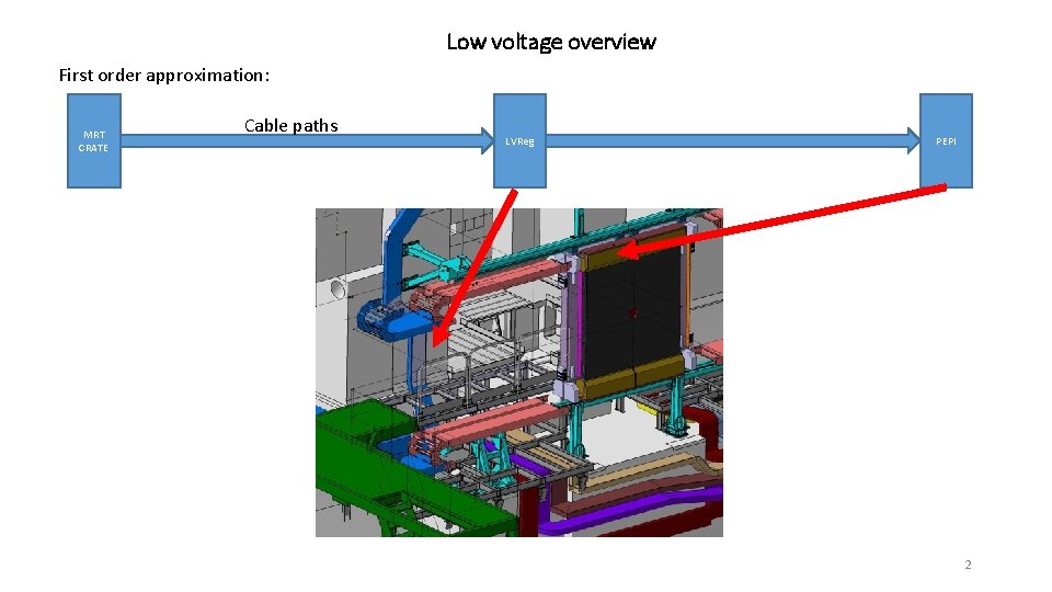
Low voltage overview First order approximation: MRT CRATE Cable paths LVReg PEPI 2
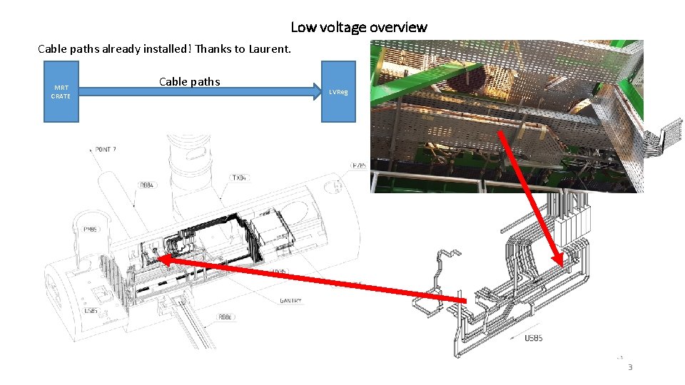
Low voltage overview Cable paths already installed! Thanks to Laurent. MRT CRATE Cable paths LVReg 3
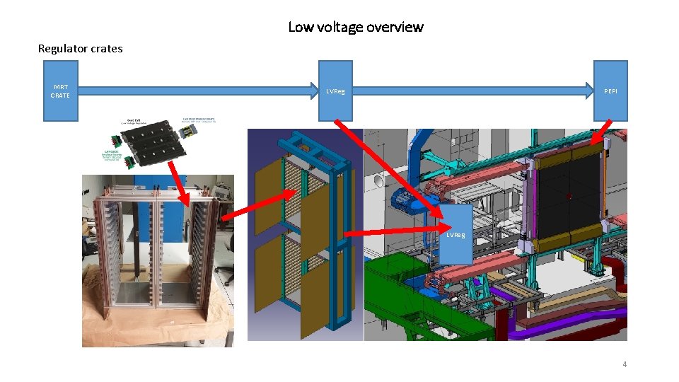
Low voltage overview Regulator crates MRT CRATE LVReg PEPI LVReg 4
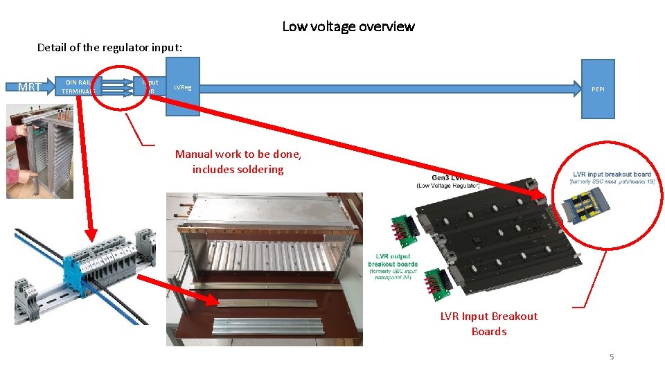
Low voltage overview Detail of the regulator input: MRT DIN RAIL TERMINALS Input BB LVReg PEPI Manual work to be done, includes soldering LVR Input Breakout Boards 5
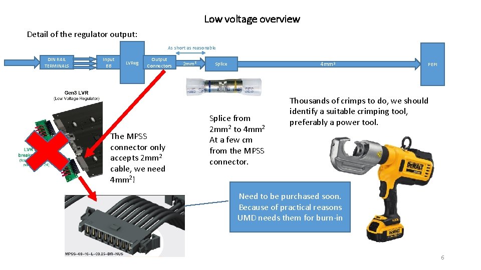
Low voltage overview Detail of the regulator output: As short as reasonable DIN RAIL TERMINALS Input BB LVReg Output Connectors The MPSS connector only accepts 2 mm 2 cable, we need 4 mm 2! 2 mm 2 4 mm 2 Splice from 2 mm 2 to 4 mm 2 At a few cm from the MPSS connector. PEPI Thousands of crimps to do, we should identify a suitable crimping tool, preferably a power tool. Need to be purchased soon. Because of practical reasons UMD needs them for burn-in 6
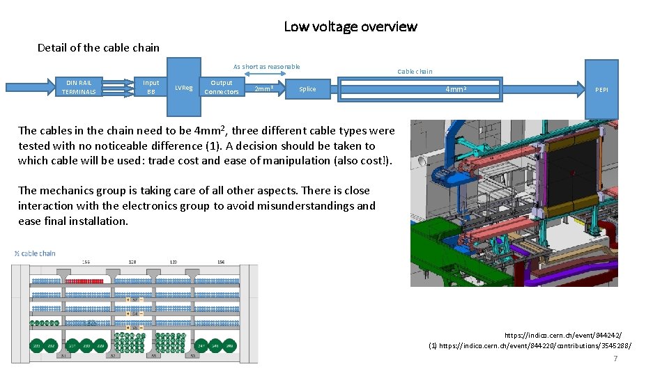
Low voltage overview Detail of the cable chain As short as reasonable DIN RAIL TERMINALS Input BB LVReg Output Connectors 2 mm 2 Splice Cable chain 4 mm 2 PEPI The cables in the chain need to be 4 mm 2, three different cable types were tested with no noticeable difference (1). A decision should be taken to which cable will be used: trade cost and ease of manipulation (also cost!). The mechanics group is taking care of all other aspects. There is close interaction with the electronics group to avoid misunderstandings and ease final installation. https: //indico. cern. ch/event/844242/ (1) https: //indico. cern. ch/event/844220/contributions/3545288/ 7
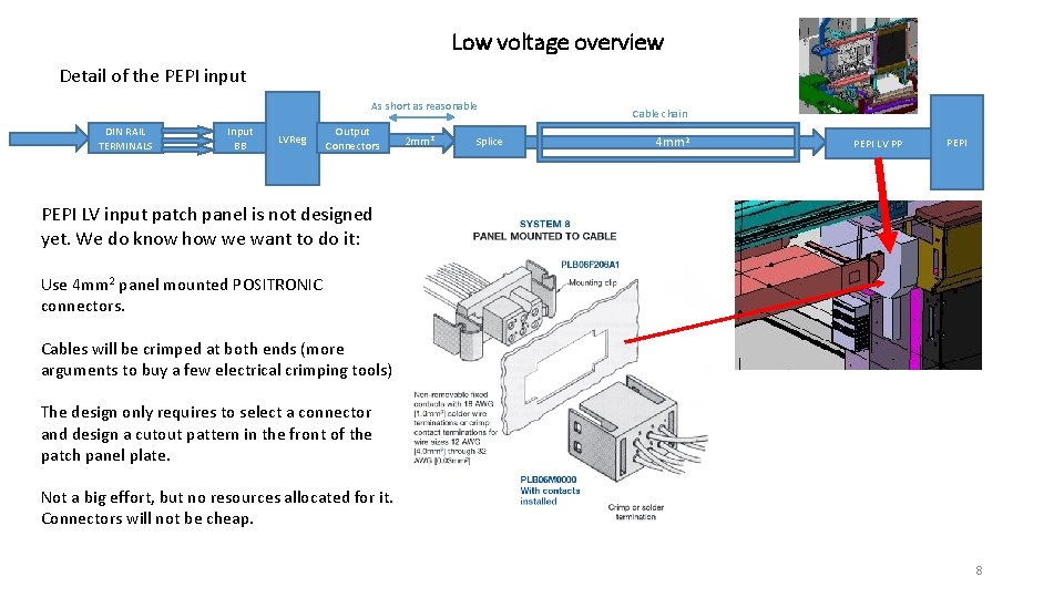
Low voltage overview Detail of the PEPI input As short as reasonable DIN RAIL TERMINALS Input BB LVReg Output Connectors 2 mm 2 Splice Cable chain 4 mm 2 PEPI LV PP PEPI LV input patch panel is not designed yet. We do know how we want to do it: Use 4 mm 2 panel mounted POSITRONIC connectors. Cables will be crimped at both ends (more arguments to buy a few electrical crimping tools) The design only requires to select a connector and design a cutout pattern in the front of the patch panel plate. Not a big effort, but no resources allocated for it. Connectors will not be cheap. 8
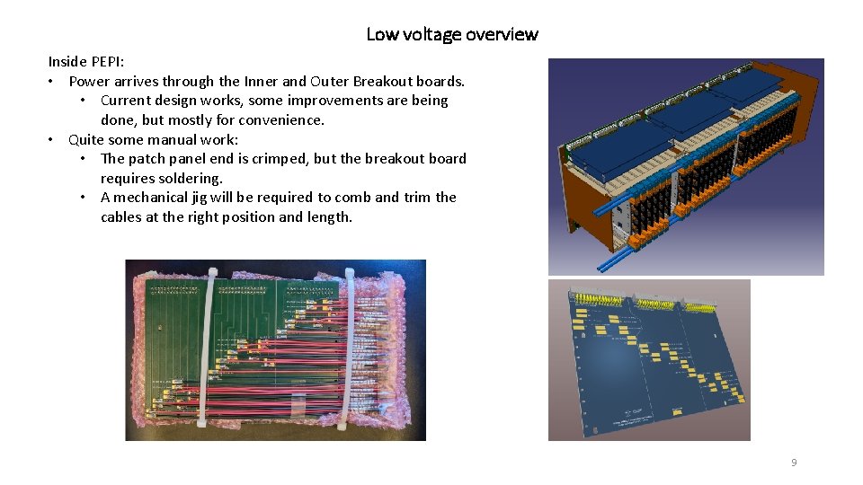
Low voltage overview Inside PEPI: • Power arrives through the Inner and Outer Breakout boards. • Current design works, some improvements are being done, but mostly for convenience. • Quite some manual work: • The patch panel end is crimped, but the breakout board requires soldering. • A mechanical jig will be required to comb and trim the cables at the right position and length. 9
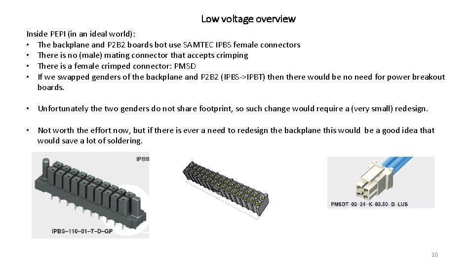
Low voltage overview Inside PEPI (in an ideal world): • The backplane and P 2 B 2 boards bot use SAMTEC IPBS female connectors • There is no (male) mating connector that accepts crimping • There is a female crimped connector: PMSD • If we swapped genders of the backplane and P 2 B 2 (IPBS->IPBT) then there would be no need for power breakout boards. • Unfortunately the two genders do not share footprint, so such change would require a (very small) redesign. • Not worth the effort now, but if there is ever a need to redesign the backplane this would be a good idea that would save a lot of soldering. 10
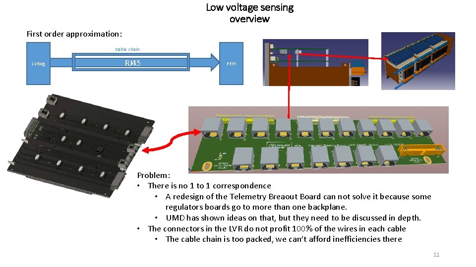
Low voltage sensing overview First order approximation: Cable chain LVReg RJ 45 PEPI Problem: • There is no 1 to 1 correspondence • A redesign of the Telemetry Breaout Board can not solve it because some regulators boards go to more than one backplane. • UMD has shown ideas on that, but they need to be discussed in depth. • The connectors in the LVR do not profit 100% of the wires in each cable • The cable chain is too packed, we can’t afford inefficiencies there 11
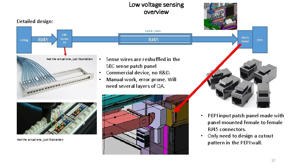
Low voltage sensing overview Detailed design: LVReg RJ 45 SBC Sense PP Not the actual one, just illustration Cable chain RJ 45 Patch Panel PEPI • Sense wires are reshuffled in the SBC sense patch panel • Commercial device, no R&D. • Manual work, error prone. Will need several layers of QA. • PEPI input patch panel made with panel mounted female to female RJ 45 connectors. • Only need to design a cutout pattern in the PEPI wall. 12
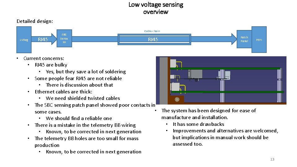
Low voltage sensing overview Detailed design: LVReg RJ 45 SBC Sense PP Cable chain RJ 45 Patch Panel PEPI • Current concerns: • RJ 45 are bulky • Yes, but they save a lot of soldering • Some people fear RJ 45 are not reliable • There is discussion about that • Ethernet cables are thick: • We need shielded twisted cables • The SBC sensing patch panel showed poor contacts in • The system has been designed for ease of some cases. manufacture and installation. • We should find a reliable one • It has some drawbacks • There is a mistake in the telemetry BB wiring • Improvements and alternatives are welcomed, • Known, to be corrected in next generation but implications in manual work should be • The telemetry BB holes are too small for mass assessed too. production • Known, to be corrected in next generation 13
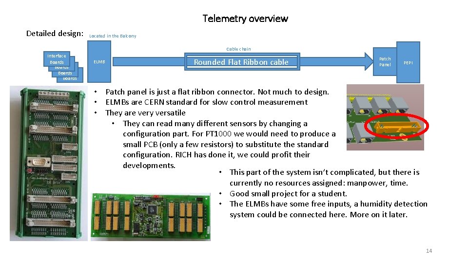
Telemetry overview Detailed design: Located in the Balcony Cable chain Interface Boards ELMB Rounded Flat Ribbon cable Patch Panel PEPI • Patch panel is just a flat ribbon connector. Not much to design. • ELMBs are CERN standard for slow control measurement • They are very versatile • They can read many different sensors by changing a configuration part. For PT 1000 we would need to produce a small PCB (only a few resistors) to substitute the standard configuration. RICH has done it, we could profit their developments. • This part of the system isn’t complicated, but there is currently no resources assigned: manpower, time. • Good small project for a student. • The ELMBs have some free inputs, a humidity detection system could be connected here. More on it later. 14
Humidity sensors overview There is controversy about that subject • FBGs are very expensive, but they would solve our problems. • The idea of remote sensing though pipes has been expressed • Copper pipes have been suggested • Integration issues • Flow issues • No pressure inside PEPI (how do we measure there? ) • Pumps have been suggested: they may suck too much air and favor humidity going inside the box • Could work, but needs to be studied • Resolution issues • The gas warms up in the pipe, 40% RH at -20ºC = 2% RH at room temperature • The proposed sensor resolution is +/-5% RH • Would require an R&D that is not happening, no guarantee of success. • CMS is qualifying some cheap commercial sensors • The sensing element can withstand the radiation, but not the associated electronics. • There is a distance limit between the two. • Not sure it works for our case, would need someone to work on it. • No dedicated manpower or resources. All solutions require having someone to work on them to succeed. • My position: I try to be agnostic and keep all options opened just in case, but someone should work on that if we ever want to converge. 15
Sumary LV: LVR Input PP: including DIN rail, producing small PCBs, connecting the ensemble Buying LVR Output connectors Validating splice: someone should try it before we bet the UT on it Find a suitable splicing tool: several thousand joints to do, we need something reliable and repeatable Decide what cables to use and cast it in stone, the tests are done already. PEPI LVR PP: Select a connector model, buy a few and validate them. Find a suitable crimping tool. • Design cutout pattern. Simple, but someone has to do it. • Give last touches to PEPI LV BBs, launch production, QA, … LV sense: • Correct issues in Telemetry BB, could discuss different cables/connectors if needed • Design PEPI remote sensing PP: only a cutout pattern • Validate a high quality Ethernet PP: would need to buy and test a couple Telemetry: • Someone needs to work on the ELMBs, get familiar, etc • Design of a PCB with a few resistors, produce a few hundreds. Copy it from Rich Humidity: • Need to find a responsible that can dedicate a few months to it because we don’t have a reliable solution that we are willing to afford. • • • 16
- Slides: 16