
Using UML SOFTWARE SYSTEM DEVELOPMENT Chapter 2 Modeling
- Slides: 48
Using UML SOFTWARE SYSTEM DEVELOPMENT Chapter 2, Modeling with UML, Part 3 UML 2 Hightlights
Outline for today • UML 2: UML is a living language • Overview of important changes in UML 2 • • • Frames and nesting Activity diagrams Deployment diagrams Sequence diagrams Profiles, Stereotypes UML Metamodel Bouchahma Majed 2
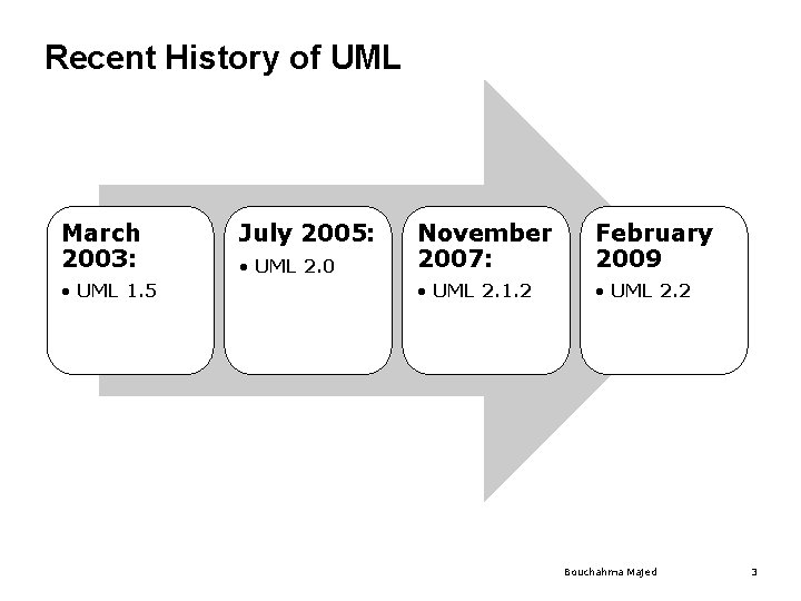
Recent History of UML March 2003: • UML 1. 5 July 2005: • UML 2. 0 November 2007: February 2009 • UML 2. 1. 2 • UML 2. 2 Bouchahma Majed 3
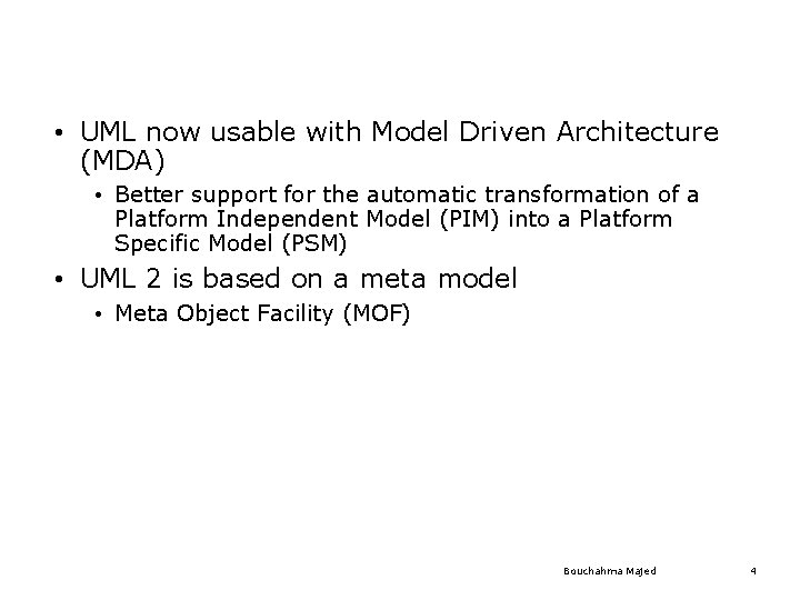
• UML now usable with Model Driven Architecture (MDA) • Better support for the automatic transformation of a Platform Independent Model (PIM) into a Platform Specific Model (PSM) • UML 2 is based on a meta model • Meta Object Facility (MOF) Bouchahma Majed 4
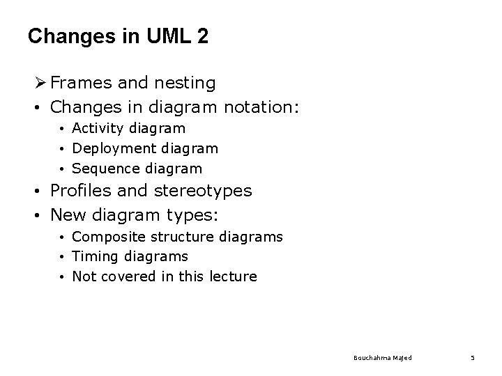
Changes in UML 2 Ø Frames and nesting • Changes in diagram notation: • Activity diagram • Deployment diagram • Sequence diagram • Profiles and stereotypes • New diagram types: • Composite structure diagrams • Timing diagrams • Not covered in this lecture Bouchahma Majed 5
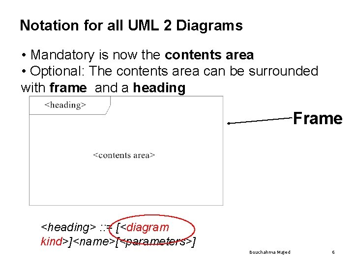
Notation for all UML 2 Diagrams • Mandatory is now the contents area • Optional: The contents area can be surrounded with frame and a heading Frame <heading> : : = [<diagram kind>]<name>[<parameters>] Bouchahma Majed 6
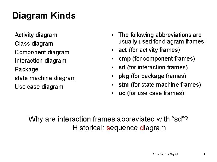
Diagram Kinds Activity diagram Class diagram Component diagram Interaction diagram Package state machine diagram Use case diagram • The following abbreviations are usually used for diagram frames: • act (for activity frames) • cmp (for component frames) • sd (for interaction frames) • pkg (for package frames) • stm (for state machine frames) • uc (for use case frames) Why are interaction frames abbreviated with “sd”? Historical: sequence diagram Bouchahma Majed 7
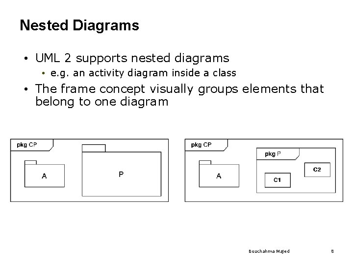
Nested Diagrams • UML 2 supports nested diagrams • e. g. an activity diagram inside a class • The frame concept visually groups elements that belong to one diagram Bouchahma Majed 8
UML 2 Activity Diagrams • An activity diagram consists of nodes and edges • There are three types of activity nodes • Control nodes • Executable nodes • Most prominent: Action • Object nodes • E. g. a document • An edge is a directed connection between nodes • There are two types of edges • Control flow edges • Object flow edges Bouchahma Majed 9
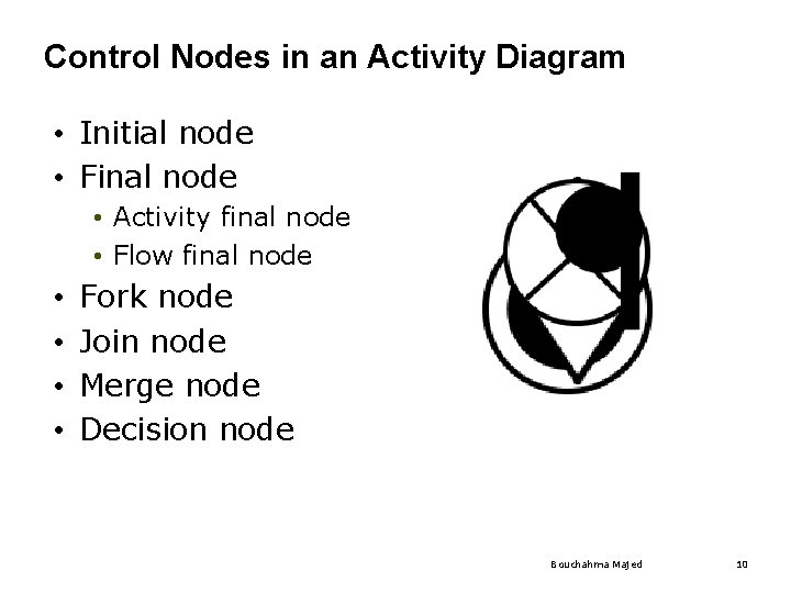
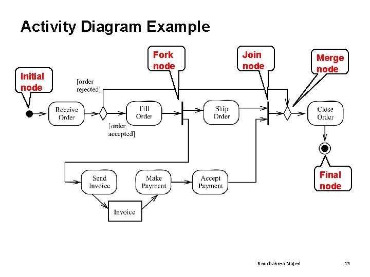
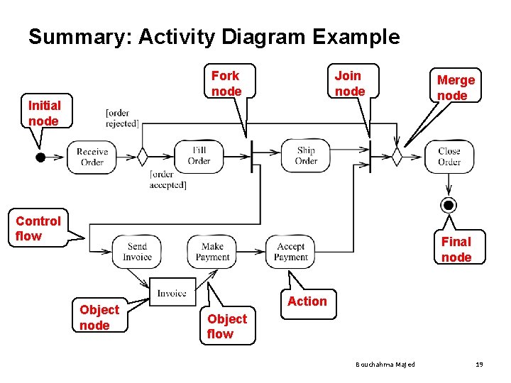
Control Nodes in an Activity Diagram • Initial node • Final node • Activity final node • Flow final node • • Fork node Join node Merge node Decision node Bouchahma Majed 10
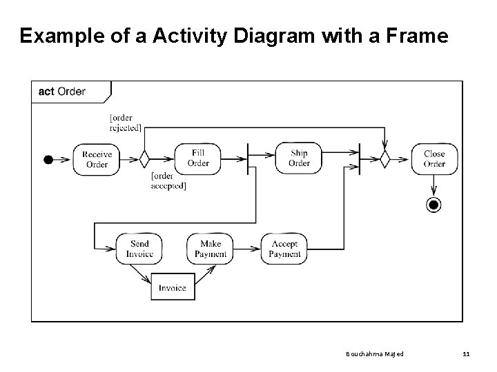
Example of a Activity Diagram with a Frame Bouchahma Majed 11
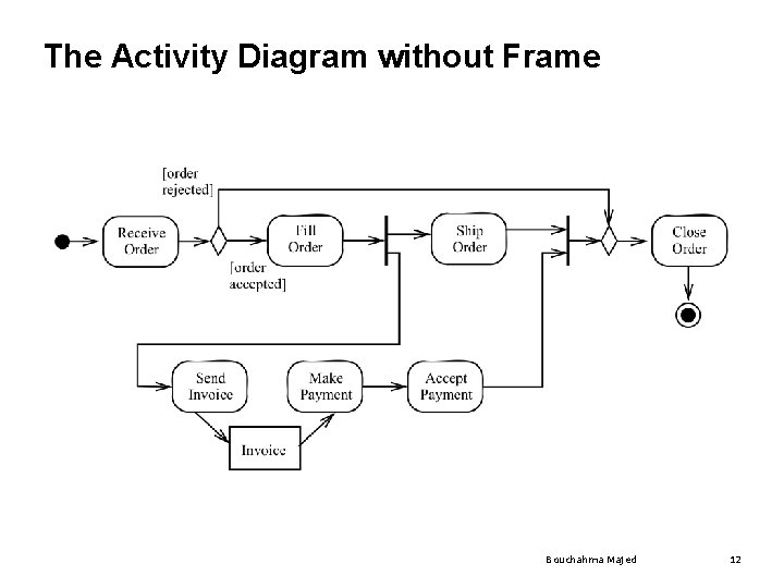
The Activity Diagram without Frame Bouchahma Majed 12
Activity Diagram Example Fork node Join node Initial node Merge node Final node Bouchahma Majed 13
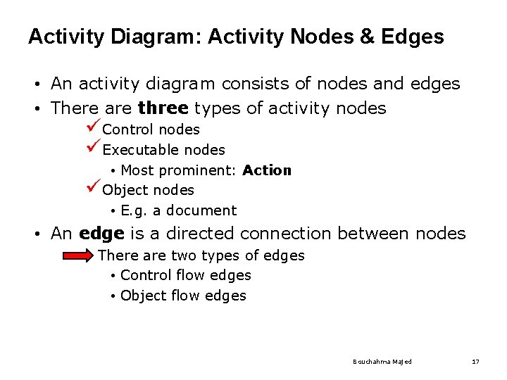
Activity Diagram: Activity Nodes & Edges • An activity diagram consists of nodes and edges • There are three types of activity nodes üControl nodes • Executable nodes • Most prominent: Action • Object nodes • E. g. a document • An edge is a directed connection between nodes • There are two types of edges • Control flow edges • Object flow edges Bouchahma Majed 14
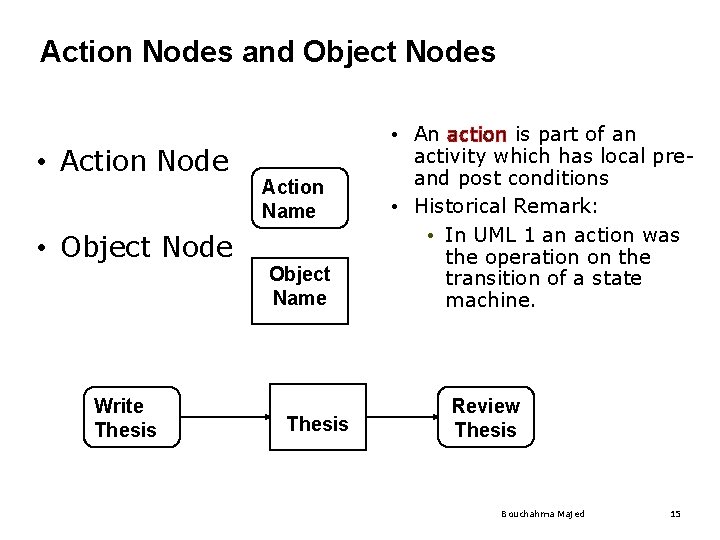
Action Nodes and Object Nodes • Action Node • Object Node Write Thesis Action Name Object Name Thesis • An action is part of an activity which has local preand post conditions • Historical Remark: • In UML 1 an action was the operation on the transition of a state machine. Review Thesis Bouchahma Majed 15
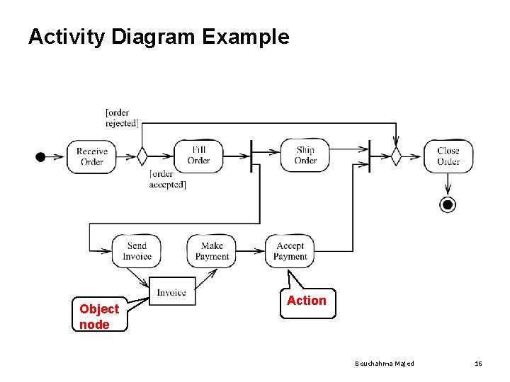
Activity Diagram Example Object node Action Bouchahma Majed 16
Activity Diagram: Activity Nodes & Edges • An activity diagram consists of nodes and edges • There are three types of activity nodes üControl nodes üExecutable nodes • Most prominent: Action üObject nodes • E. g. a document • An edge is a directed connection between nodes • There are two types of edges • Control flow edges • Object flow edges Bouchahma Majed 17
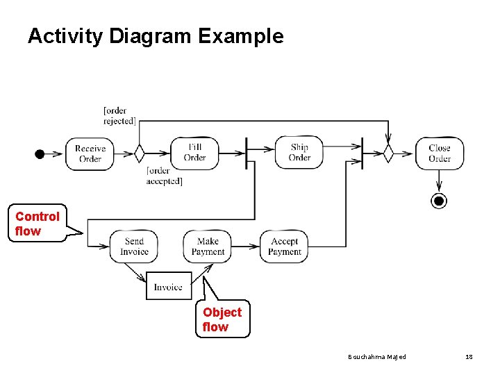
Activity Diagram Example Control flow Object flow Bouchahma Majed 18
Summary: Activity Diagram Example Fork node Join node Initial node Control flow Merge node Final node Object node Action Object flow Bouchahma Majed 19
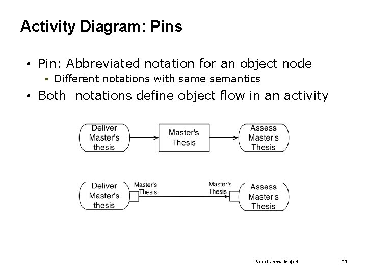
Activity Diagram: Pins • Pin: Abbreviated notation for an object node • Different notations with same semantics • Both notations define object flow in an activity Bouchahma Majed 20
Outline for today ü UML 2: UML is a living language ü Overview of important changes in UML 2 ü Frames and nesting ü Activity diagrams Ø Deployment diagrams • Sequence diagrams • Profiles, Stereotypes • UML Metamodel Bouchahma Majed 21
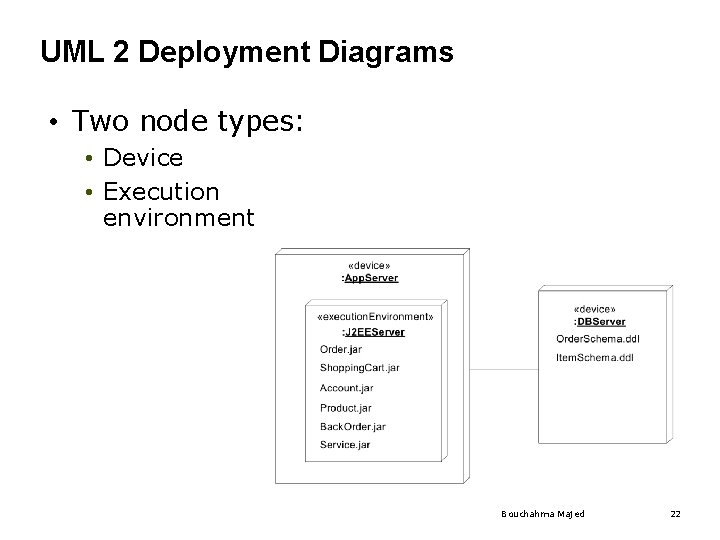
UML 2 Deployment Diagrams • Two node types: • Device • Execution environment Bouchahma Majed 22
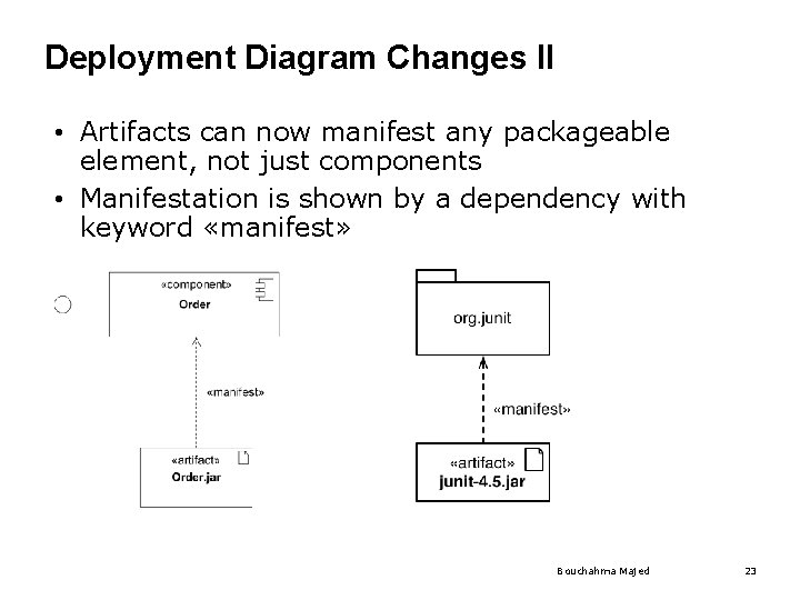
Deployment Diagram Changes II • Artifacts can now manifest any packageable element, not just components • Manifestation is shown by a dependency with keyword «manifest» Bouchahma Majed 23
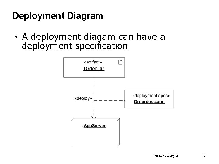
Deployment Diagram • A deployment diagam can have a deployment specification Bouchahma Majed 24
Sequence Diagram Changes • New concept of interaction fragments • Before going into detail with interaction fragments, we cover the concept of an interaction Bouchahma Majed 25
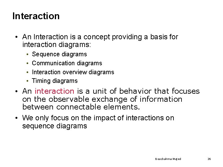
Interaction • An Interaction is a concept providing a basis for interaction diagrams: • • Sequence diagrams Communication diagrams Interaction overview diagrams Timing diagrams • An interaction is a unit of behavior that focuses on the observable exchange of information between connectable elements. • We only focus on the impact of interactions on sequence diagrams Bouchahma Majed 26
Usage of Interactions • UML Interactions are used to get a better grip of an interaction situation • Interactions are also used during the detailed design phase if precise inter-process communication must be set up according to formal protocols • When testing is performed, the traces of the system can be described as interactions and compared with those of the earlier phases. Bouchahma Majed 27
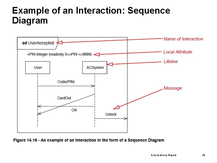
Example of an Interaction: Sequence Diagram Bouchahma Majed 28
Explanation for the Previous Slide • The sequence diagram on the previous slide shows three messages between two anonymous lifelines of type User and ACSystem: Code. Pin, Card. Out and OK • The message Card. Out overtakes the message OK in the way that the receiving event occurrences are in the opposite order of the sending event occurrences. • Such communication may occur when the messages are asynchronous. • A fourth message Unlock is sent from the ACSystem to the environment • Through a gate with the implicit name out_Unlock. Bouchahma Majed 29
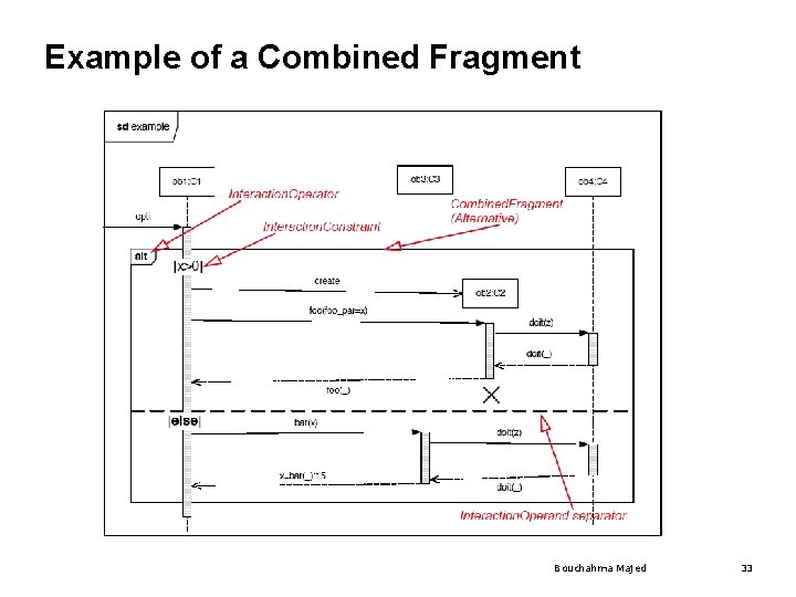
Interaction Fragment • Is a piece of an interaction • Acts like an interaction itself • Combined Fragment • Is a subtype of interaction fragment • defines an expression of interaction fragments • defined by an interaction operator and corresponding interaction operands Bouchahma Majed 30
Interaction Operators • A combined fragment defines an expression of interaction fragments. The following operators are allowed in an combined fragment expression: • • • Alt Opt Par Loop Critical Neg Assert Strict Seq Ignore Consider Bouchahma Majed 31
Alt and Else Operators • The interaction operator alt designates that the combined fragment represents a choice of behavior. • At most one of the operands will be chosen. The chosen operand must have an explicit or implicit guard expression that evaluates to true at this point in the interaction. An implicit true guard is implied if the operand has no guard. • The set of traces that defines a choice is the union of the (guarded) traces of the operands. • An operand guarded by else designates a guard that is the negation of the disjunction of all other guards in the enclosing combined fragment. • If none of the operands has a guard that evaluates to true, none of the operands are executed and the remainder of the enclosing interaction fragment is executed. Bouchahma Majed 32
Example of a Combined Fragment Bouchahma Majed 33
Opt and Break Operators • Option: The interaction operator opt designates a choice of behavior where either the (sole) operand happens or nothing happens. • Break: The interaction operator break represents a breaking scenario: The operand is a scenario that is performed instead of the remainder of the enclosing interaction fragment. • A break operator with a guard is chosen when the guard is true • When the guard of the break operand is false, the break operand is ignored and the rest of the enclosing interaction fragment is chosen. • The choice between a break operand without a guard and the rest of the enclosing interaction fragment is done non-deterministically. Bouchahma Majed 34
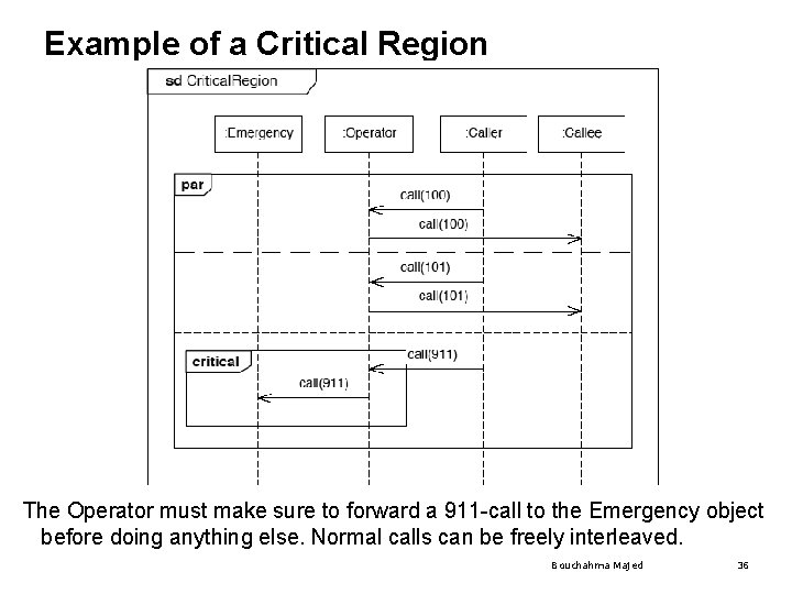
Parallel and Critical Operator • Parallel: The interaction operator par designates a parallel merge between the behaviors of the operands of a combined fragment. • The event occurrences of the different operands can be interleaved in any way as long as the ordering imposed by each operand is preserved. • A parallel merge defines a set of traces that describes all the ways that event occurrences of the operands may be interleaved. • Critical: The interaction operator critical designates that the combined fragment represents a critical region. • The traces of the region cannot be interleaved by other event occurrences (on the Lifelines covered by the region). This means that the region is treated atomically by the enclosing fragment. Bouchahma Majed 35
Example of a Critical Region The Operator must make sure to forward a 911 -call to the Emergency object before doing anything else. Normal calls can be freely interleaved. Bouchahma Majed 36
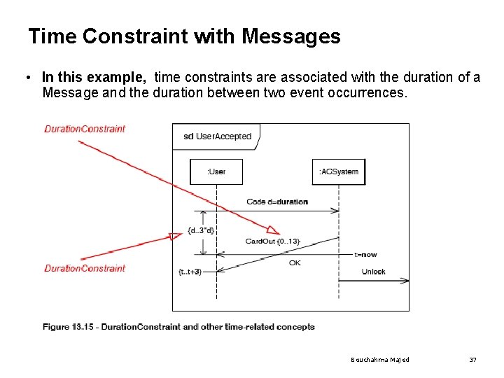
Time Constraint with Messages • In this example, time constraints are associated with the duration of a Message and the duration between two event occurrences. Bouchahma Majed 37
Where are we? ü Introduction ü Frames and nesting ü Changes in diagram notation: ü Activity diagram ü Deployment diagram ü Sequence diagram Ø Profiles and stereotypes Bouchahma Majed 38
Meta Modeling • Meta model: A model describing a model • Meta class: Part of the meta model, describing the structure of a model element • Why are we talking about this? • Meta models can be used to explain the UML notation • More about this in Friday’s lecture but we need the term meta class already to explain UML profiles and stereotypes. Bouchahma Majed 39 39
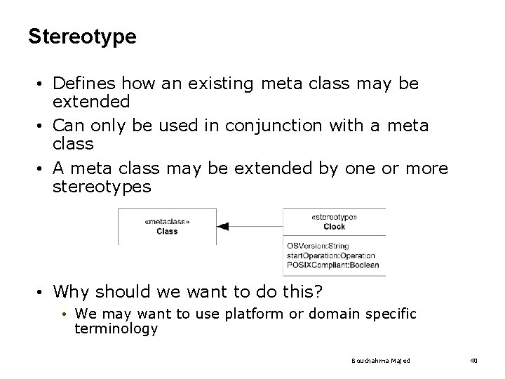
Stereotype • Defines how an existing meta class may be extended • Can only be used in conjunction with a meta class • A meta class may be extended by one or more stereotypes • Why should we want to do this? • We may want to use platform or domain specific terminology Bouchahma Majed 40
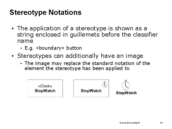
Stereotype Notations • The application of a stereotype is shown as a string enclosed in guillemets before the classifier name • E. g. «boundary» button • Stereotypes can additionally have an image • The image may replace the standard notation of the element the stereotype has been applied to Bouchahma Majed 41
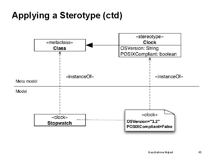
Applying a Stereotype • The attributes of a stereotype are called tagged values • Applying a stereotype to an instance of a meta class means instantiating the stereotype • If the stereotype has attributes, you have to provide values for them • Confused? See following slide… Bouchahma Majed 42
Applying a Sterotype (ctd) Bouchahma Majed 43
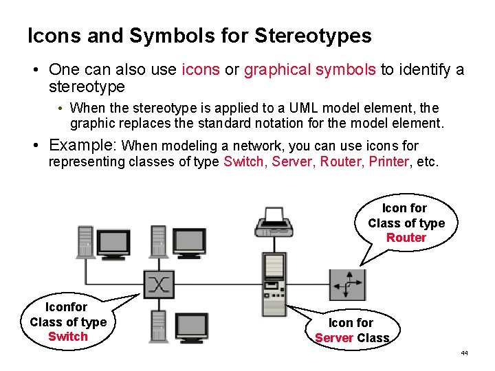
Icons and Symbols for Stereotypes • One can also use icons or graphical symbols to identify a stereotype • When the stereotype is applied to a UML model element, the graphic replaces the standard notation for the model element. • Example: When modeling a network, you can use icons for representing classes of type Switch, Server, Router, Printer, etc. Icon for Class of type Router Iconfor Class of type Switch Icon for Server Class Bouchahma Majed 44
Pros and Cons of Stereotype Graphics • Advantages: • UML diagrams may be easier to understand if they contain graphics and icons for stereotypes • This can increase the readability of the diagram, especially if the client is not trained in UML • And they are still UML diagrams! • Disadvantages: • If developers are unfamiliar with the symbols being used, it can become much harder to understand what is going on • Additional symbols add to the burden of learning to read the diagrams • If you end up applying stereotypes all over your model, you should think of defining a profile. Bouchahma Majed 45
Stereotypes vs. Keywords • Not to be mixed up with keywords • Same notation (String enclosed in guillemets) • «interface» is no stereotype! • «extend» is no stereotype! • See Annexes B and C of the UML Superstructure specification. Bouchahma Majed 46
UML Profiles • A lightweight extension mechanism for UML • Concepts partially present in earlier versions • Stereotypes • Tagged Values • Established as a specific meta-modeling technique in UML 2. 0 • Contains mechanisms that allow meta classes from existing meta models to be extended • ability to tailor the UML meta model for different platforms or domains • consistent with the OMG Meta Object Facility (MOF) • MOF will be covered in the next lecture on metamodeling. Bouchahma Majed 47
Additional Readings • UML 2. 2 specification • The specification consists of two complementary parts which constitute the complete speciication of UML 2: • Infrastructure and Superstructure. • The infrastructure specification defines the foundational language constructs • http: //www. omg. org/spec/UML/2. 2/Infrastructure/PDF • The superstructure defines the user level constructs. • http: //www. omg. org/spec/UML/2. 2/Superstructure/PDF • For a complete list of all UML specifications, see • http: //www. omg. org/spec/UML/ Bouchahma Majed 48