Use Case Diagrams Use case A use case


 refers to an interaction with any type of")


 or system (occasionally) existing outside the system. •")


![• Generalization [between use cases]: “A taxonomic relationship between a more general classifier](https://slidetodoc.com/presentation_image_h2/4163fef9ff4059409ec1e0bde1f66142/image-36.jpg "• Generalization [between use cases]: “A taxonomic relationship between a more general classifier")
 • Scenario : A specific sequence of actions that")


- Slides: 48
Use Case Diagrams
• Use case: A use case is the specification of a set of actions performed by a system, which yields an observable result that is, typically, of value for one or more actors or other stakeholders of the system. • A use case is a usage of the system that provides an observable and (usually) meaningful result. The use-case documentation (diagrams and/or text) should delineate the series of steps that take place during the interaction and include different ways that this interaction could play out. • Over time, practitioners began to distinguish between two kinds of use cases: business use cases and system use cases. This distinction is not part of the core UML but it is a valid and widely accepted UML extension
• A use case (unqualified) refers to an interaction with any type of system. The question is, what type of system is being referring to? • A business use case is an interaction with a business system. For example, Process Claim is a business use case describing an interaction with an insurance company. • A system use case is an interaction with an IT system. For example, system use cases that support the aforementioned business use case are Record Claim, Validate Coverage, Assign Adjuster, and so on. Each of these describes an interaction between a user and the computer system. A system use case typically involves one active (primary) user and takes place over a single session on the computer. At the end of the system use case, the user should feel that he or she has achieved a useful goal.
• use cases are used to document our understanding of the way a business operates – business requirements modeling – and to specify what our new software system should be able to do – system requirements modeling. The business use cases in this book use an informal, descriptive style: they describe, for the benefit of nonexperts, something that already exists. The system use cases, on the other hand, will be more prescriptive: they specify, mainly for the benefit of software developers, exactly what functionality needs to be implemented.
Business Perspective • A business model can be as simple as a class diagram, showing the relationships between business entities – this is sometimes referred to as a domain model. A domain model may be sufficient for small projects, however, for most projects, we would want to produce an entire business model representing how the business operates, or at least that part of the business that surrounds the system we expect to develop. • Use cases are not the only way of modeling a business, but they’re simple. More complex alternatives include business process modeling and workflow analysis. Use cases are simple because producing one doesn’t require specialist knowledge, just common sense and a certain amount of logic. The use case model that we produce here will contain the use cases themselves plus some other bits and pieces:
Business Use Case • A business use case defines what should happen in the business when it is performed; it describes the performance of a sequence of actions that produces a valuable result to a particular business actor (someone external to the business) • Any IT project has the potential to change the business environment—how steps (both manual and automated) within a business are performed and the roles and responsibilities of employees. By focusing on business use cases at the outset of the project, you ensure that this business perspective is not forgotten
Business Use Case Diagrams • “The business use-case model is a diagram illustrating the scope of the business being modeled. The diagram contains business actors [roles played by organizations, people, or systems external to the business] and the services or functions they request from the business. ”
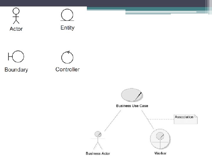
Elements • Business actor: Someone external to the business, such as a customer or supplier. • Worker: Someone who works within the business, such as an employee or acustomer-service representative. • Association: An association between an actor and a business use case indicates that the actor interacts with the business over the course of the business use case—for example, by initiating the use case or by carrying it out.
• Actor: A person (usually) or system (occasionally) existing outside the system. • Boundary: An object at the edge of the system, between the system and the actors. For system actors, boundaries provide a communication path. For human actors, a boundary means a user interface, capturing commands and queries and displaying feedback and results. Each boundary object usually corresponds to a use case, or a group of related use cases. More specifically, such a boundary usually maps to a user interface sketch (in which case it may be an entire interface or just a subwindow). It is quite reasonable for boundary objects to survive through to design.
• Entity: An object inside the system, representing a business concept such as a customer, a car or a car model and containing useful information. Typically, entities are manipulated by boundary and controller objects, rather than having much behavior of their own. Entity classes are the ones that appear on our analysis class diagram. Most entities survive through to design. • Controller: An object inside the system that encapsulates a complex or untidy process. A controller is a service object that provides the following kinds of service: control of all or part of a system process; creation of new entities; retrieval of existing entities. Without controllers, our entities would become polluted with messy details. Since controllers are just a convenience for the benefit of analysis, we do not expect many of them to survive through to design; an important exception to this is the idea of a home. A home is a controller that is used for the creation of new entities and the retrieval of existing ones. A home may also have utility messages as in car. Model. Home. find. Engine. Sizes(). Since a home is such a clean concept, they often survive through to design.
Actors • In this step, you identify the IT system’s users, or actors. Previously, when we spoke of actors, it was in relation to business use-case modeling. There we spoke of business actors and workers. • An actor specifies a role played by a user or any other system that interacts with the subject • An actor is a type of user or an external system that interacts with the system under design • External agent/external entity: Equivalent terms used in structured analysis. • Stakeholder: A term more inclusive than actor as it includes anyone who the project will affect even if they do not have direct contact with it.
Finding Actors • To find actors, go through your list of business actors and workers, eliminating any who don’t interact with the IT system. Then add any external systems and human users who are required because of the technology. (Remember that when you performed business use-case modeling, your focus was not on technology, so you may have missed some of these actors. )
Stereotypes and Actors • A stereotype is an extension of a UML feature. Modelers can invent their own stereotypes to create extended meanings to UML model elements. • Stereotypes in the UML can be depicted either by using a special symbol, such as the stick figure, or by using the regular UML symbol and including the name of the stereotype inside guillemets, as in <<stereotype-name>>. In the case of actors, some people like to reserve the stick figure for human users and use the guillemet option for external systems.
Depicting Actors and Stereotypes
• Business actor: An actor appearing in the business requirements. • Business object: An object appearing in the business requirements. • System actor: An actor appearing in the system requirements. • System object: An object appearing (inside the system) in the system requirements. • Analysis object: An object appearing in the analysis model. • Deployment artifact: Something deployed in the system, such as a file. • Design object: An object appearing in the design model. • Design node: A computer or process that forms part of the system architecture. • Design layer: A vertical partition of a subsystem. • Design package: A logical grouping of classes, used to organize the development.
The Role Map • A role map is a diagram used to standardize the treatment of users and external systems throughout the project. A role map is a restricted form of a usecase diagram. Whereas the use-case diagram shows actors and their associations with use cases, the role map shows only actors. • Place icons for each of the actors you’ve identified in the role map. The role map then becomes the central diagram team members go back to whenever they want to know how to depict a user in the model. You can also use the role map to show the ways in which user roles overlap.
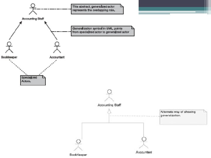
Modeling Actors with Overlapping Roles • You document actors with overlapping roles by drawing a generalization relationship between actors. Any time the phrase “a kind of” comes up in the discussion of actors, think about using the generalization relationship. For example, a Bookkeeper and an Accountant are two kinds of Accounting Staff. • Two types of situations: ▫ Actors whose roles partially overlap ▫ An actor whose role completely encompasses another’s
• When two actors have some overlap in their roles, but each actor can do things with the system that the other can’t, model the actors as specialized actors and invent an abstract generalized actor to represent the overlap. The term generalized implies that the specialized actors inherit something from the generalized actor. In this case, the specialized actors inherit the ability to do all the things that the generalized actor can do. • The generalized actor is not a true role but an abstract concept meant to represent the shared aspects of other roles.
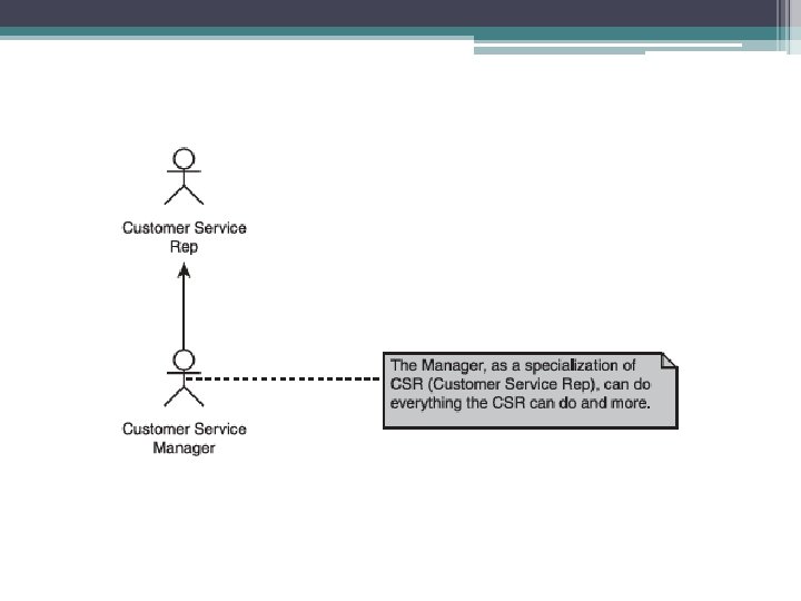
Modeling an Actor Whose Role Totally Encompasses Another’s • In other cases, an actor might be able to do everything that another actor can do and more. In this situation, model the actor with the restricted role as the generalized actor, and model the actor with the larger role as the specialized actor. This may look odd at first, since the • diagram tends to make the lesser role “more important. ” This is due to the common practice of drawing the generalized actor above the specialized actor. • The generalized actor, in this case, is not an invention but a real role. It is therefore considered to be a concrete (as opposed to abstract) actor.
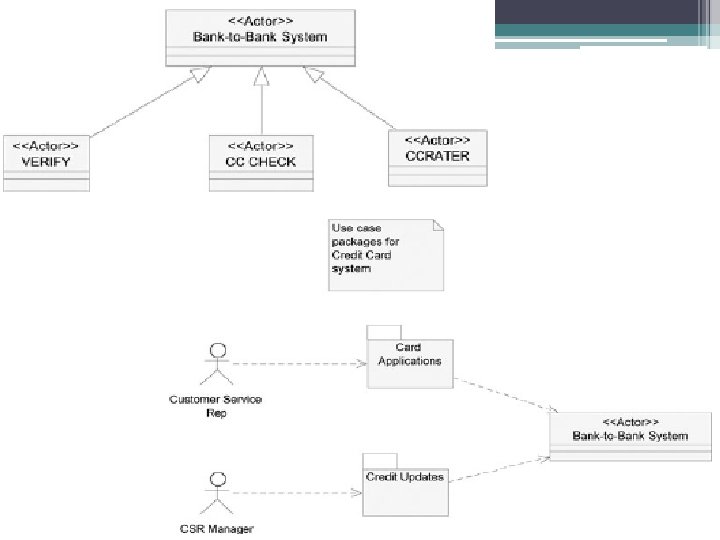
System Use-Case Diagram • If your project supports only one business use case, you may proceed directly to the following step, identify system use cases. But if it supports a number of business use cases, consider creating system use-case packages. A system use-case package is a collection of system use cases and the diagrams that describe them. The UML package icon looks like (and acts similarly to) a Windows folder. By defining the packages now, you are, in effect, setting up a filing system that all members of the team will use once the analysis really gets under way.
Criteria to Used Use Cases into Packages? • Group system use cases by the main actor who uses them. For example, group together into one package all the system use cases used by general administration. • Create a system use-case package for each business use case. For example, in an insurance system, the customer sees the end-to-end process, Make a Claim. To the customer, this represents one business goal; however, to achieve it, the company’s workers require a number of discrete interactions with the computer system: Record claim, Validate policy, Adjust claim and Pay claim
Naming Use-Case Packages • Formally, because a package is a thing— specifically, a container—it should be named with a noun phrase. On the other hand, because of the way we are using the packages, it makes sense to name each package according to the business use case it supports. This makes tracing easier—from the business use-case model we worked on earlier to the system use-case model we are now developing. Either approach is acceptable.
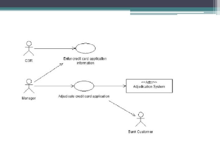
System Use Cases • Once you’ve decided what system use cases are required to support a business use case, you document your findings in a system use-case diagram. Create one (or more if necessary) system use-case diagram for each system use-case package. • The system use-case diagram shows which actors participate in each system use case. The diagram does not show sequencing; you can’t tell from the diagram the order in which the system use cases should be used or the sequence of activities within each use case. • Primary actor: An actor who initiates a use-case interaction (indicated as an actor at the tail end of an arrow pointing to a use case). • Secondary actor: An actor that the system initiates an interaction with after the use case has started (indicated as an actor at the tip of an arrow pointing from a use case). • System use case: A user task (indicated as an oval).
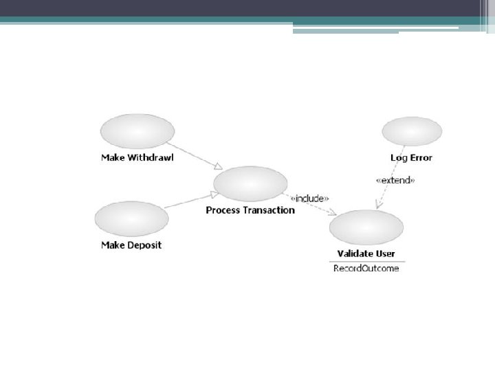
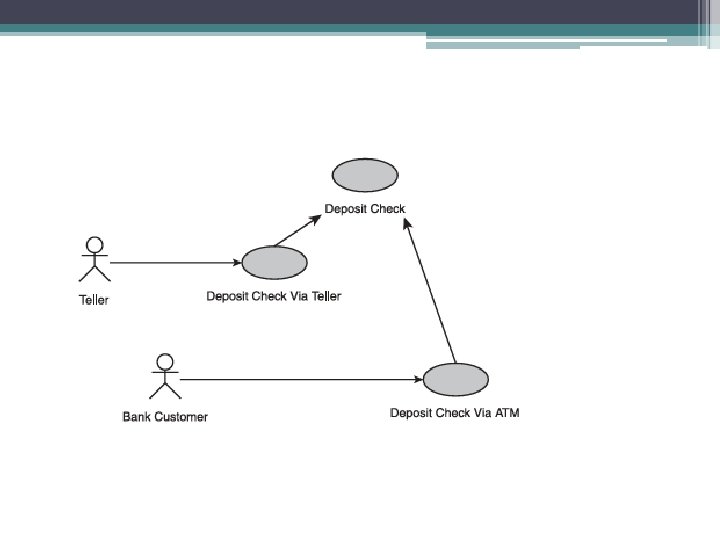
Use-case Relationship • Specializes: Just like actors, use cases can inherit from each other. In order to avoid all sorts of complexity relating to the redefinition of steps and the addition of extra ones. • Include: Extract the common requirements into a “mini use case. ” The main use cases are said to include this mini use case. This approach is useful whenever a set of steps appears in more than one system use case. • Extend: You leave one main system use case intact and create a new use case that extends the original one. The extending use case contains only the requirements that differ from the original. This approach is useful, for example, for enhanced versions of earlier software releases. • Generalization: You create a new generalized use case that contains general rules. Other use cases are created as “specializations”; they contain the nongeneric requirements. This approach is useful when a set of system use cases represents variations on a theme
<<Include>> • An include relationship between two use cases means that the behavior defined in the including use case is included in the behavior of the base use case. The include relationship is intended to be used when there are common parts of the behavior of two or more use cases. This common part is then extracted to a separate use case, to be included by all the base use cases having this part in common. Since the primary use of the include relationship is for reuse of common parts, what is left in a base use case is usually not complete in itself but dependent on the included parts to be meaningful. This is reflected in the direction of the relationship, indicating that the base use case depends on the addition but not vice versa. • When the same set of steps appears in more than one use case, extract them into a separate use case—called an included use case—and refer to them from the main use cases—referred to as base use cases. When modeling an include relationship between two use cases, draw a dashed arrow, pointing from the base use case to the included use case.
Include
<<Extends>> Use this feature whenever you need to add requirements to an existing use case without changing the original text. The following are some common reasons for an extension : • Seldom-used options that the user can choose at any time (known as asynchronous interruptions): An extending use case will allow you to handle these options in separate extending use cases and keep the base use case free of the seldom-used requirements. Aside from the clarity this provides, it is also useful for planning software iterations: You may plan to implement the base use case in an early iteration and add the extending use cases later. • Customization of a generic product: The generic product is described in the base use case. The extending use case describes the customization.
• You may extract a group of alternate flows that are triggered by the same conditions into a separate use case, referred to as an extending use case. In the main (extended) use case, you define locations (extension points) where the flow may be interrupted; in the extending use case, you document the extracted flows, the conditions that trigger them, and the location where each alternate flow interrupts the extended use case.
Generalized Use Case • Use this feature when a number of use cases represent variations on a theme. Common reasons for a generalized use case are the following: • Technology variations: The same user goal is achieved using different technologies. Define a generalized use case to hold rules that apply regardless of technology; handle the technology variations as specialized use cases. • Similar process but different business artifacts: The business has a standard process for handling different kinds of artifacts (for example, different kinds of application forms), but the process differs slightly depending on the artifact. Handle the generic rules in a generalized use case and describe the peculiarities in specialized use cases—one for each artifact.
• Generalization [between use cases]: “A taxonomic relationship between a more general classifier [use case] and a more specific classifier [use case]. Each instance of the specific classifier [use case] is also an indirect instance of the general classifier [use cases]. Thus, the specific classifier [use case] indirectly has features of the more general classifier [use case]. The UML does not have a specific definition for generalized use cases, but its broader definition applies to use cases. If one use case could be considered a specific type of another, the general one may be modeled as a generalized use case and the specific type as a specialized use case. For example, if there are three types of use cases for processing a transaction. • Anything true for the generalized use case is true for all of its specialized use cases. For example, if the model indicates that an actor is associated with the generalized use case.
The Use Case Description (Scenario) • Scenario : A specific sequence of actions that illustrates behaviors. A scenario may be used to illustrate an interaction or the execution of a use-case instance. • A scenario is one path through a use case—one way that it might play out. • When writing scenario, it’s important that we specify the function of the system but not the way that function is delivered: for example, if we were to include steps such as 2. Customer clicks on the Details. . . button, we would be restricting the user interface designer. Unless it’s an absolute requirement, you should always try to use neutral words like select, initiate, indicate and display.
• • The use case number and title. Whether the use case is abstract. relationships to other use cases. Any preconditions (conditions that must be satisfied before the use case is carried out). The steps themselves (where we can assume that the preconditions have been met). Any postconditions (conditions that are guaranteed after successful completion of the use case). Any abnormal paths and what to do in each case (although the paths are abnormal, we include them if it’s important for us to specify the system’s reaction). Any nonfunctional requirements that relate to this use case.
The Use-Case Description • The underlying principle of this template is to describe workflow using a simple narrative style that avoids complex logic. The trick to keeping things simple is to handle variations in a separate area of the document rather than in one all-encompassing section. First, you document a normal, typical interaction in a section called “Basic Flow. ” Next, you describe alternative success scenarios in an “Alternate Flows” section. Finally, you describe error handling in an “Exceptional Flows” section.
Use-Case Description Template 1. Use Case: The use-case name as it appears on system use-case diagrams Perspective: Business use case/system use case Type: Base use case/extending/included/generalized/specialized 1. 1 Brief Description: Describe the use case in approximately one paragraph. 1. 2 Business Goals and Benefits: Briefly describe the business rationale for the use case. 1. 3 Actors 1. 3. 1 Primary Actors: Identify the users or systems that initiate the use case. 1. 3. 2 Secondary Actors: List the users or systems that receive messages from the use case. Include users who receive reports or online messages. 1. 3. 3 Off-Stage Stakeholders: Identify non-participating stakeholders who have interests in this use case.
1. 4 Rules of Precedence 1. 4. 1 Triggers: Describe the event or condition that “kickstarts” the use case, such as Call received; inventory low. If the trigger is time-driven, describe the temporal condition, such as End-of-month. 1. 4. 2 Pre-conditions: List conditions that must be true before the use case begins. If a condition forces the use case to occur whenever it becomes true, do not list it here; list it as a trigger. 1. 5 Post-conditions 1. 5. 1 Post-conditions on Success: Describe the status of the system after the use case ends successfully. Any condition listed here is guaranteed to be true on successful completion. 1. 5. 2 Post-conditions on Failure: Describe the status of the system after the use case ends in failure. Any condition listed here is guaranteed to be true when the use case fails as described in the exception flows. 1. 6 Extension Points: Name and describe points at which extending use cases may extend this use case. Example of extension point declaration: “Preferred Customer: 2. 5– 2. 9. ”
2. Flow of Events Basic Flow: Insert basic flow steps. Numbers begin with 2. 1. Alternate Flows 2. Xa Insert the alternate flow name. The alternate flow name should describe the condition that triggers the alternate flow. “ 2. X” is the step number in the basic flow where the interruption occurs. Describe the steps in paragraph or point form. Exception Flows 2. Xa Insert the exception flow name. The exception flow name should describe the condition that triggers the exception flow. An exception flow is one that causes the use case to end in failure and for which “post-conditions on failure” apply. “ 2. X” is the step number in the basic flow where the interruption occurs. Describe the steps in paragraph or point form.
• Documenting the Basic Flow More Explanations. . . The basic flow describes the most common way that the use case plays out successfully. (Some people call it the “happy scenario. ”) It reads as a straightforward narrative: “The user does. . . ; the system does. . ” As a rule of thumb, the basic flow should not list any conditions, since subsequent sections handle all errors and alternatives. To keep documentation consistent, employ a style guideline throughout your company for writing use-case requirements. • Documenting Alternate Flows Document each scenario not covered in the basic flow as an alternate flow or as an exception flow. An alternate flow is a variation that does not lead to the abandonment of the user goal; an exception flow involves a nonrecoverable error. If your team has trouble deciding whether to list a scenario in the “Alternate Flow” or “Exception Flow” section, merge the two sections into one and list both types of flows there. • An alternate flow is a scenario other than the basic flow that leads to success. An alternate flowmay deal with a user error as long as it is recoverable. Nonrecoverable errors are handled as exception flows.
• Documenting Exception Flows List each error condition that leads to the abandonment of the user goal in the “Exception Flows” section. Typical exception flows include cancellation of a transaction by the user and system errors that force a transaction to be canceled. Documentation rules are the same as for the alternate flows except that there is often no convergence point, since the goal is abandoned. In that case, the last line of the flow should read, “The use case ends in failure. ”
Are Use Cases All You Need • People often ask me if the use cases are all of the requirements or whether they are all you need to create test cases. The answer to both questions is, “No. ” • First of all, they are not all of the requirements because they only address the user requirements, omitting other requirements such as security requirements. • Secondly, they focus on the flow of the conversation between the system and the actors—the storyboard of the interaction. Other issues, such as screen designs and datavalidation rules, are defined in other artifacts that the use case links to. To fully document and test a system, you need use cases and these other artifacts. • Decision Tables • Use a decision table to describe the system response to a number of interrelated factors. If each factor can be looked at separately, do not use a decision table; just use the alternate and exceptional flows or, alternatively, a condition/response table.
Ex. Decision Table