US Forest Service Forest Inventory and Analysis URBAN

US Forest Service Forest Inventory and Analysis URBAN PLOT Boundaries Urban 2019
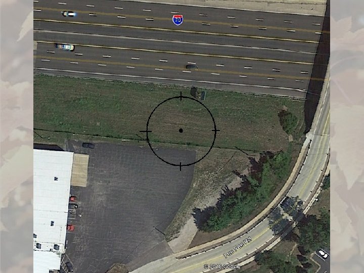
 (Crosses Subplot")
2 Types of Urban Boundaries TRADITIONAL CLOSED (Does NOT Cross Subplot Perimeter) (Crosses Subplot Perimeter)

Boundary Plot Type SUBPLOT UTYPE= 1 MICROPLOT UTYPE=2

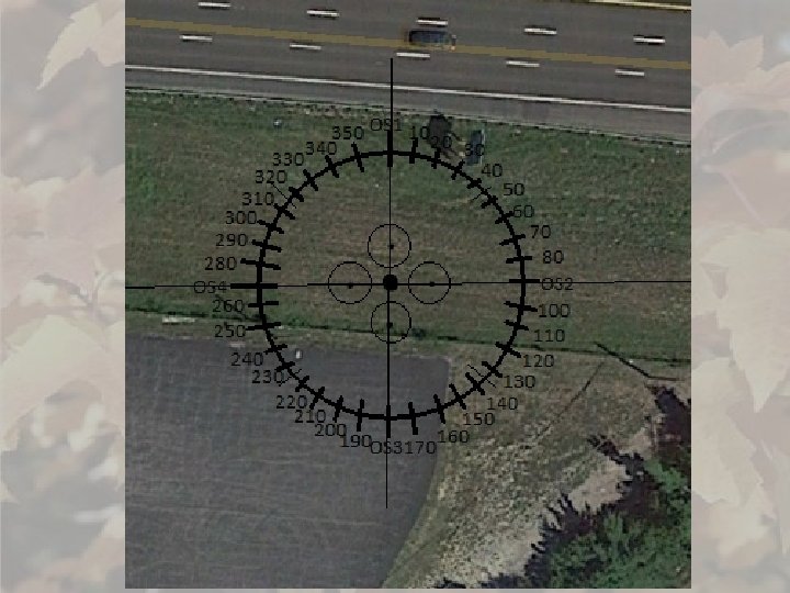
LEFT AZIMUTH CORNER AZIMUTH RIGHT AZIMUTH
")
Traditional Boundary Corner Distance CORNER DISTANCE (to nearest ft. )

LEFT 340° COND 2 CORNER 120° 26 ft COND 1 RIGHT 140°

Closed Boundary DOES NOT CROSS SUBPLOT PERIMETER CROSS= 0 N 3 N 4 0 - NORMAL N 2 N 1

Closed Boundary CROSSES SUBPLOT PERIMETER CROSS= 1 N 4 N 3 0 - NORMAL N 1 N 2

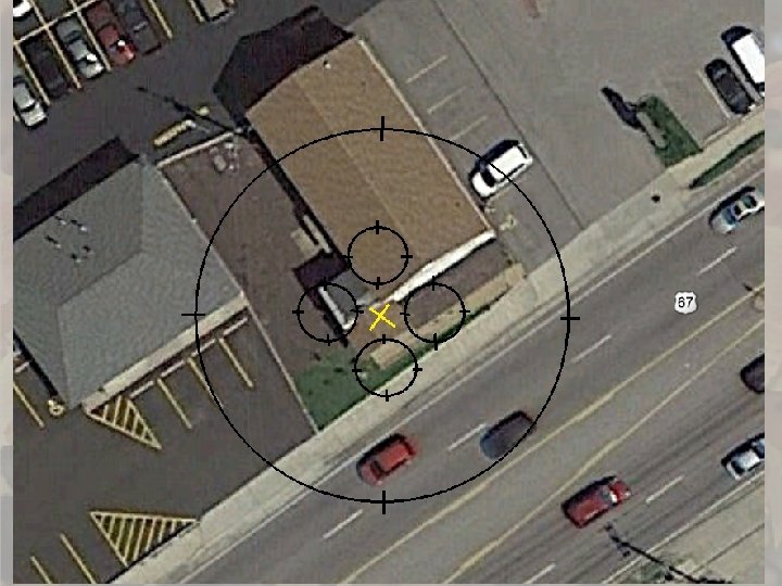
COND 2 250°, 43 ft N 2 N 4 285° N 3 COND 1 91° 300°, 30 ft N 1

N 1 107°, 37 ft 310° N 2 COND 3 198°, N 4 41 ft COND 1 287° N 2 N 3 170° N 1 20° COND 2

Urban Boundary Rules • Traditional boundaries & closed boundaries cannot be mixed (URBAN PLOT TYPE=1). • Microplot boundaries (URBAN PLOT TYPE = 2) may ONLY be defined using traditional boundaries. • When defining boundaries on a plot, it is also required that the REMAINING CONDITION be recorded. That will be entered on the SUBPLOT screen. • Closed boundaries cannot intersect or share an edge. • The condition at subplot center must always be CONDITION 1. • There are minimum lengths for internal boundary segments depending on the type of boundary. • Traditional Boundaries • Closed Boundary, Crosses Subplot Perimeter • Closed Boundary, Does not Cross Perimeter No minimum 14’ minimum 20’ minimum

Urban Boundary Hints • Create Microplot Boundaries -Microplot boundaries can be populated based on the subplot boundaries by using the create microplot boundaries function from the boundary menu in the PDR. o enter the MAPPED CONDITION field to complete the populated microplot boundary information. o It is critical to review the microplot boundaries/microplot center condition as calculated by the PDR tool and correct the boundary record if it appears different from the boundary as observed on the ground. • Edit the boundary using CTRL W or CTRL X • Check the Urban Boundary Diagram function (CTRL Z) to make sure everything looks right.

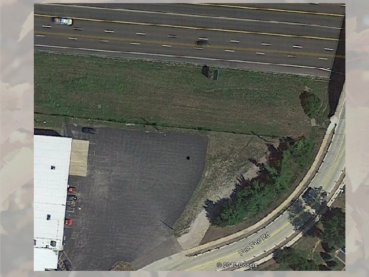
Drawing Boundaries from Offset Points

Offset Points 0 - NORMAL 3 - SOUTH

Traditional Boundary Offset Azimuths 0 - NORMAL CENTER AZIMUTH RIGHT AZIMUTH LEFT AZIMUTH 3 - SOUTH

Traditional Boundary Offset Corner Distance 0 - NORMAL CORNER DISTANCE 3 - SOUTH

Closed Boundary 1 - NORTH N 4 DOES NOT CROSS SUBPLOT BOUNDARY N 3 0 - NORMAL 4 - WEST 2 - EAST N 2 N 1 3 - SOUTH

Closed Boundary N 4 N 3 No need to return to N 1 0 - NORMAL N 2 N 1 2 - EAST

Closed Boundary Nodes Azimuth and Distance 1 - NORTH CROSSES SUBPLOT BOUNDARY N 1 MUST N 1 START HERE N 2 CLOCKWISE N 3 N 4 N 5


Left Right

- Slides: 26